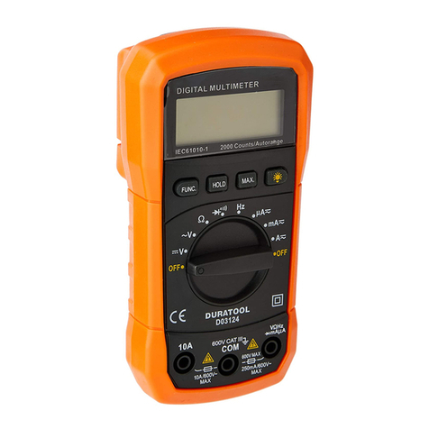
Duratool D03124 User manual

1
MODEL: D03124
DIGITAL MULTIMETER

2
IMPORTANT SAFETY INFORMATION
Please read these instructions carefully before use and retain for future
reference.
This instrument is designed and manufactured in compliance with: G84793,
lEC61010-1, CAT III 600V, Pollution Degree 2 and Double Insulation standards.
• Check the test leads, probes and case insulation before using. If you nd any
breakage or abnormality, or you consider the device is broken, stop using the
device immediately.
• Comply with local and national safety code. Wear personal protection equipment
(such as rubber gloves, masks and ame retardant clothes etc.) to prevent being
injured by electric shock due to exposed hazardous live conductors.
• When using the test probes, keep your ngers behind the nger protection ring.
• Do not use the meter with the back cover open.
• Select appropriate test range for measurements.
• Ensure all inputs are less than the range selected otherwise it may cause electrical
shock or meter damage.
• Do not change the range selector position during voltage or current
measurements.
• Do not apply more than the rated voltage as marked on the meter, between the
terminals or between any terminal and earth ground.
• Take caution when working voltages are above 60V DC or 30V AC rms.
• Do not connect the meter to voltage signals when the range selector is on current,
resistance, diode or continuity range.
• When a measurement has been completed, disconnect the testing probes from
the circuit under test.
• Do not use the meter around explosive gas or vapour.
• Replace the batteries as soon as the low battery indicator appears on the display.
• Remove dead batteries from the meter or if it is not going to be used for a long
time.
• Never mix old and new batteries together, or different types of batteries.
• Never dispose of batteries in a re, or attempt to recharge ordinary batteries.
• Before replacing the battery, turn off the meter and disconnect all the test probes.
• To prolong battery life turn off the meter after use.
• CAT III: Measurement category III is for measurements performed in the building
installation. Examples are measurements on distribution boards, circuit-breakers,
and wiring, such as cables, bus-bars, junction boxes, switches and socket-outlets
in the xed installation, and equipment for industrial application and some other
equipment such as stationary motors with permanent connection to the xed
installation.
• Only use test leads and probes that are in compliance with IEC 61010-031, and
rated CAT III 600V.
WHAT’S INCLUDED
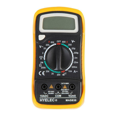
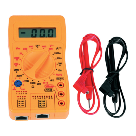
• Digital multimeter
• User manual
• Set of test leads
3
SAFETY SYMBOLS
Symbol Description
High Voltage Warning
AC (Alternating Current)
DC (Direct Current)
AC or DC
Warning - Important Safety Information
Ground
Fuse
Double Insulation
Low Battery
CAT. III 600V CAT. III 600V over-voltage protection
FUNCTIONS
1. LCD display
2. “MAX” push button
3. “BACK LIGHT” push button
4. “HOLD” push button
5. “FUNC” Push button
6. Rotary Selector
7. ”V/Ω/HZ/uA/mA” Input terminal
8. “COM” input terminal
9. “10A” input terminal
1
2
3
6
7
5
4
9
8

4
1Auto-power off 8Hold mode
2DC voltage indicator 9Low battery indicator
3Negative reading indication 10 Frequency indication
4AC indicator 11 Temperature Unit
5Diode Measurement 12 Function indicator
6Continuity buzzer mode 13 Resistance indicator
7Max value indicator 14 Main measurement display
BUTTONS
Button Details
FUNC Function select key that acts with trigger. Use the key as switch of DC/
AC current, Diode/Continuity and Hz.
HOLD Press “HOLD” to enter and exit the hold mode in any mode.
MAX Press this key once, the maximum value is holding (Will displays ‘MAX’
symbol in the LCD). After pressing the key, ND will keep working, and the
display value are always up dated and kept the maximum value. NOTE:
The actual gained value is not the peak value.
When press and hold the key for over 2 sec, will enable the back light.
Press the key again, the back light will disable.
DISPLAY
2
3
4
5 6 7 8 9
10
11
12
13
14
1
MEASURE AC & DC VOLTAGE
• Insert the red test lead into the “VΩ” input terminal and the black test lead into the
COM terminal.
• Set the rotary switch to DC or AC range.
Connect the test lead across with the object under test.
• The measured value will be show on the LCD display.
• When DC or AC voltage measurement has been completed, disconnect the
connection between the test leads and the circuit under testing.

5
MEASURE RESISTANCE
DIODE AND CONTINUITY CHECK
• The resistance range are: 200.0Ω, 2.000KΩ, 20.00KΩ, 200.0KΩ, 2.000MΩ,
20.00MΩ.
• To measure resistance, connect the meter as follows:
• Insert the red test lead into the “ VΩ” terminal and the black test lead into the COM
terminal.
• Set the rotary switch to proper resistance range.
• Connect the test lead across with the object under testing.
• The measured value will be show on the LCD display.
NOTE: The test lead can add 0.10 to 0.20 of error to resistance measurement. To
obtain precision reading in low-resistance measurement, that is the range of 200.0Ω,
short the input terminals before measuring. The contact resistance is displayed on the
LCD. You can subtract the contact resistance value from the measured value.
• For high-resistance measurement (>10MΩ), it is normal taking several second to
obtain stable reading.
• If the LCD displays “OL” indicates an open-circuit for the tested resistor or the
resistance value is higher than the maximum range of the meter.
Diode
• Set the rotary switch to “ ” position.
• Default mode is diode check mode. You can enter the continuity check mode by
pressing the “FUNC” Key.
• Insert the red test lead into the “VΩ’’ terminal and the black test lead into the
“COM” terminal.
• Use the diode test mode to check diodes, transistors and other semiconductor
device. In the diode test mode sends a current through the semiconductor junction,
and the measure the voltage drop across the junction. A good silicon junction drop
between 0.5V and 0.8V.
• For forward voltage drop reading on any semiconductor component, place the red
test lead on the component anode and place the black test lead on the component
cathode.
• The measured value show on the display.
• Reverse the test leads and measure the voltage across the diode again/ If the
diode is good the display shows “OL”.
Continuity
• Press “FUNC” to enter continuity mode.
• The buzzer sounds if the resistance is less than 100Ω.
FREQUENCY MEASUREMENT
• Set the rotary switch to “Hz” position.
• Insert the red test lead into the “VΩHz” input terminal and the black test lead into
the “COM” terminal.
• Connect the test leads across with the circuit under testing.
• The measured value shown on the LCD display.
NOTE: Input signal level must be higher than 0.5V.

6
CURRENT MEASUREMENT
• Turn off power to the circuit.
• Set the rotary switch to the appropriate DC/AC µA or DC/AC mA position.
• Break the current path to be tested.
• Connect the red test lead to the positive side of the break and the black test lead
to the negative side of the break.
• Turn on the power to the circuit.
• The measured value shows on the display.
NOTE: for high current measurement insert the red test lead into the input
terminal marked as “10A”. The measuring procedure is the same as for low power
measurement.
• For safety’ s sake, the measuring time for high current should be ≤10 second for
each measurement and the interval time between two measurement should be
greater than 5 minutes.
• When current measurement has been completed, disconnect the connection
between the test leads and the circuit under testing.
OPERATING PARAMETERS
• Ambient temperature 23º± 5º
• Relative Humidity: <75%
DC VOLTAGE
AC VOLTAGE
Range Resolution Accuracy
200mV 0.1mV
±(0.5%+2)
2V 0.001V
20V 0.01V
200V 0.1V
600V 1V ±(0.8%+2)
Range Resolution Accuracy
2V (40Hz-400Hz) 0.001V
±(0.5%+2)
20V (40Hz-400Hz) 0.01V
200V (40Hz-400Hz) 0.1V
600V (40Hz-200Hz) 1V ±(0.8%+2)
Note: Over load protection: Maximum 600V DC or AC RMS
CONTINUITY AND DIODE TEST
Range Description Testing Condition
Displays the forward voltage of
the diode. Resolution 0.001V
Forward DC current is about 1mA.
Open circuit voltage is about 1.48V
When resistance ≤100Ω, the
buzzer beeps. Open circuit voltage is about 0.5V.

7
RESISTANCE
Range Resoluon Accuracy
200Ω 0.10Ω
±(0.8%+2)
2kΩ 0.001kΩ
20kΩ 0.01kΩ
200kΩ 0.1kΩ
2MΩ 0.001MΩ ±(1.0%+2)
20MΩ 0.01MΩ
DC CURRENT
Range Resolution Accuracy
200μA 0.1μA
±(1.5%+3)
2mA 1μA
20mA 0.01mA
200mA 0.1mA
10A 0.01A ±(2.0%+5)
Notes:
• Overload protection:
• μA, mA input: 500mA/600V Φ6x32mm.
• 10A input: 10A/600V Φ6x32mm.
• Max input current: 250mA at ‘mA’ input terminal.
• Maximum input current: 10A (For current over 5A, measuring time must not
exceed 10 seconds).
FREQUENCY
Range Resoluon Accuracy
20kHz 10KHz ±(1.5%+5)
Notes: Sensitivity: 0.8V
AC CURRENT
Range Resoluon Accuracy
200μA 0.1μA
±(1.5%+5)
2mA 1μA
20mA 0.01mA
200mA 0.1mA
10A 0.01A ±(2.5%+5)

8
Notes:
• Overload Protection:
• uA, mA input: 500mA/600V Φ6x32mm.
• 10A input: 10A/600V Φ6x32mm.
• Max input current: 250mA at ‘mA’ input terminal.
• Maximum input current: 10A (For current over 5A, measurement time must not
exceed 10 seconds).
• Frequency response: 40Hz~400Hz.
BATTERY REPLACEMENT
Warning: Only replace the battery after the test leads are removed and the power is off.
To replace the battery,
• Unscrew and remove the battery cover.
• Replace the battery with a new 9V battery of the same type.
• Ret the cover.
To replace the fuses,
• To avoid electrical shock, remove the test lead and any
input signal before opening the bottom case.
• Open the bottom case and then remove the defective fuse
and insert a new fuse of the same size and rating.
• Replace the bottom case and reinstall all the screws.
• Clean the meter with a clean, soft cloth.
• Do not use any chemicals, abrasives or solvents that could damage the meter.
CLEANING
GENERAL SPECIFICATION
Battery
Screw
INFORMATION ON WASTE DISPOSAL FOR CONSUMERS OF
ELECTRICAL & ELECTRONIC EQUIPMENT
These symbols indicate that separate collection of Waste Electrical and Electronic Equipment
(WEEE) or waste batteries is required. Do not dispose of these items with general household
waste. Separate for the treatment, recovery and recycling of the materials used. Waste batteries
can be returned to any waste battery recycling point which are provided by most battery retailers.
Contact your local authority for details of the battery and WEEE recycling schemes available in
your area. Made in China
PO Box 13362 Dublin 2
PR2 9PP
Man Rev 1.1
• Auto ranging DMM, full scale 2000 counts.
• Display: 3 1/2 digit LCD display.
• Over load protection: Used the PTC protection circuit for resistance, frequency
measurement.
• DATA HOLD function.
• MAX value hold function.
• Back Light.
• Low battery indication.
• Auto Power- OFF: If the meter is idle for 15 minutes (idle time), the meter
automatically turns the power off.
Other manuals for D03124
1
Table of contents
Other Duratool Multimeter manuals

Duratool
Duratool D03126 User manual

Duratool
Duratool D03124 User manual

Duratool
Duratool D03046 User manual

Duratool
Duratool D03131 User manual

Duratool
Duratool D03046 Assembly instructions

Duratool
Duratool D03125 User manual

Duratool
Duratool D03305 User manual

Duratool
Duratool D03143 User manual

Duratool
Duratool D03127 User manual

Duratool
Duratool D03145 User manual