www.durite.co.uk
FLASH PATTERNS
0-441-30/32/35LEAF
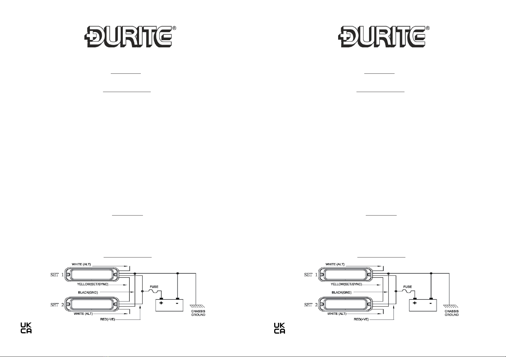
1. Switch Patterns: (Yellow wires touch Red wires)
6QEJCPIGVQPGZVƃCUJRCVVGTP
With the LED Light Heads switched on, momentarily apply +VDC to YELLOW wires for less than 1 sec-ond
and release. To reset:
With the LED Light Heads switched on, quickly apply three times + VDC toYELLOW wires and release.
LED Light Head will reset to the factory default pattern (Pattern # 0, Random)
2. Synchronization: (More than 2 sets of LED Light Heads)
First, connectYELLOW wires of all heads together, quickly apply three times + VDC toYELLOW wires and
release for Pattern # 0, Random.
Secondly, momentarily apply + VDC to YELLOW wires to for less than 1 second and release for Pattern #
1, then the synchronization will be functioned.
3. Alternating or Simultaneous Flash: (More than 2 sets of LED Light Heads)
Under Synchronization, connect WHITE wire of LED Light Head 1 to Red wires of all other LED Light
Heads; LED Light Head 1 will alternate with other LED Light Heads.
+HVJG9*+6'YKTGPQVEQPPGEVGFVQ4GFYKTGUCNN.'&.KIJV*GCFUYKNNƃCUJVQIGVJGT5KOWNVCPGQWU
ƃCUJ
4. Flash Patterns: 20 selectable strobe patterns
Type........................................................Ultra High Intensity LED
Colour.....................................................0-441-30 = AMBER. 0-441-32= BLUE. 0-441-35 = RED
Number of LEDs....................................3
Voltage...................................................12-24VDC
Current...................................................0.35A @ 12VDC
Flash patterns........................................20
Base........................................................Aluminium
Operating temperature........................-20C - +50C.
Protection..............................................IP68
Weight....................................................0.030Kg
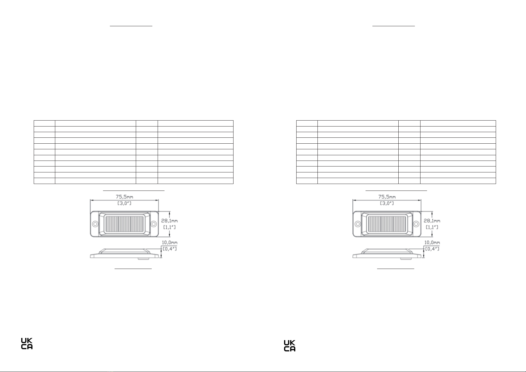
Dimensions...........................................Please see above diagram
Compliance...........................................UKCA, ECE R10, R65 Class 1, SAE Class 1
SPECIFICATION
DIMENSIONAL DRAWING
No. Flash Pattern No. Flash Pattern
0 Random (default) 10 Single (all) (SAE)
1 Single (split) 11 Double (all)
2 Double (split) 12 Quad (all)
3 Quad (split) 13 Quint (all)
4 Quint (split) 14 Mega (all)
5 Mega (split) 15 Ultra (all)
6 Ultra (split) 16 Single-Quad (all)
7 Single-Quad (split) 17 Single H/L (all)
8 Single H/L (split) 18 Steady 2 (California)
9 Single (all) (R65) 19 Steady 4 (all)
www.durite.co.uk
FLASH PATTERNS
0-441-30/32/35LEAF
1. Switch Patterns: (Yellow wires touch Red wires)
6QEJCPIGVQPGZVƃCUJRCVVGTP
With the LED Light Heads switched on, momentarily apply +VDC to YELLOW wires for less than 1 sec-ond
and release. To reset:
With the LED Light Heads switched on, quickly apply three times + VDC to YELLOW wires and release.
LED Light Head will reset to the factory default pattern (Pattern # 0, Random)
2. Synchronization: (More than 2 sets of LED Light Heads)
First, connectYELLOW wires of all heads together, quickly apply three times + VDC toYELLOW wires and
release for Pattern # 0, Random.
Secondly, momentarily apply + VDC to YELLOW wires to for less than 1 second and release for Pattern #
1, then the synchronization will be functioned.
3. Alternating or Simultaneous Flash: (More than 2 sets of LED Light Heads)
Under Synchronization, connect WHITE wire of LED Light Head 1 to Red wires of all other LED Light
Heads; LED Light Head 1 will alternate with other LED Light Heads.
+HVJG9*+6'YKTGPQVEQPPGEVGFVQ4GFYKTGUCNN.'&.KIJV*GCFUYKNNƃCUJVQIGVJGT5KOWNVCPGQWU
ƃCUJ
4. Flash Patterns: 20 selectable strobe patterns
Type........................................................Ultra High Intensity LED
Colour.....................................................0-441-30 = AMBER. 0-441-32= BLUE. 0-441-35 = RED
Number of LEDs....................................3
Voltage...................................................12-24VDC
Current...................................................0.35A @ 12VDC
Flash patterns........................................20
Base........................................................Aluminium
Operating temperature........................-20C - +50C.
Protection..............................................IP68
Weight....................................................0.030Kg
Dimensions...........................................Please see above diagram
Compliance...........................................UKCA, ECE R10, R65 Class 1, SAE Class 1
SPECIFICATION
DIMENSIONAL DRAWING
No. Flash Pattern No. Flash Pattern
0 Random (default) 10 Single (all) (SAE)
1 Single (split) 11 Double (all)
2 Double (split) 12 Quad (all)
3 Quad (split) 13 Quint (all)
4 Quint (split) 14 Mega (all)
5 Mega (split) 15 Ultra (all)
6 Ultra (split) 16 Single-Quad (all)
7 Single-Quad (split) 17 Single H/L (all)
8 Single H/L (split) 18 Steady 2 (California)
9 Single (all) (R65) 19 Steady 4 (all)