Dyaco XBR55 User manual

S
Se
er
rv
vi
ic
ce
e
M
Ma
an
nu
ua
al
l
1
XBR55
Service Manual

S
Se
er
rv
vi
ic
ce
e
M
Ma
an
nu
ua
al
l
2
--------------------------------------------Table of Contents-------------------------------------------
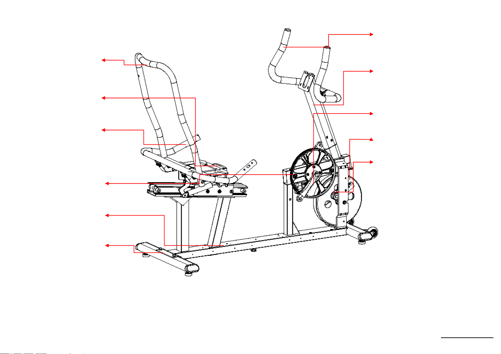
1. Recumbent Controllers Outlines
Outlines
Skeleton
2. Electronic Parts
Upper Controllers
Lower Controller and Driver
3. Electrical Configurations
4. Product Operation
5. Unit Block Diagrams
6. Basic Connections and Wiring
7. Product Safety Instructions
8. Error Messages / Troubleshooting
9. Troubleshooting
9-1 Console Disassembling and assembling
9-2 Console Mast and Cover
9-3 Crank Arm and Pedal
9-4 Front Shroud & Round Disk
9-5 Gear Motor, Steel Cable and Reed Switch Sensor
9-6 Drive Pulley Axle and Drive Pulley
9-7 Flywheel and Drive Pulley
9-8 Disassembling/Assembling of Seat Carriage Cover and Seat Back Bracket
9-9 Release Lever and Steel Cable
9-10 Gas Cylinder (Remark 8)
9-11 Seat, Seat Handle Bar and Handpulse W/Cable
9-11 Rear Shrouds and Harness
9-12 Buttons on The Handle Bar (Remark 9)
9-13 Rear Shrouds and Harness
9-14 Seat Carriage
9-15 Aluminum Trail and Stabilizer Cover

S
Se
er
rv
vi
ic
ce
e
M
Ma
an
nu
ua
al
l
3
9-16 Console
9-17 Belt Slipping and Falling-off
9-18 Noises

S
Se
er
rv
vi
ic
ce
e
M
Ma
an
nu
ua
al
l
4
1. XBR55 Outlines

S
Se
er
rv
vi
ic
ce
e
M
Ma
an
nu
ua
al
l
5
Console
Assembly
Mast Handle bar
Assembly
Mesh Seat Back
Pedal (R)
Crank Arm (L)
Round Disk
Pedal (L)
Front Shroud (L)
Cable Assembly(L)
Seat
Drink Bottle Holder (R)
Aluminum Track
Rear Shroud (R)
Bottom Cover
Handgrip End Cap

S
Se
er
rv
vi
ic
ce
e
M
Ma
an
nu
ua
al
l
6
Seat Back Bracket
Seat Carriage
Seat Handle Bar
Main Frame
Rear Stabilizer
Drive Pulley
Handle Bar Cover
Console Mast
Crank Arm End Cap
Flywheel
Idler Wheel Assembly

S
Se
er
rv
vi
ic
ce
e
M
Ma
an
nu
ua
al
l
7
2. Electronic Parts

S
Se
er
rv
vi
ic
ce
e
M
Ma
an
nu
ua
al
l
8
Upper Controllers
Cooling FAN
DISPLAY

S
Se
er
rv
vi
ic
ce
e
M
Ma
an
nu
ua
al
l
9
Lower Controller and Driver
SPEED SENSOR
TENSION MOTOR

S
Se
er
rv
vi
ic
ce
e
M
Ma
an
nu
ua
al
l
10
3.Electrical Configurations

S
Se
er
rv
vi
ic
ce
e
M
Ma
an
nu
ua
al
l
11
CONSOLE:
Interface that controls all functions of the Bike.
TENSION MOTOR:
It can change to increase or decrease resistance level of brake.
GENERAL INFORMATION
CONSOLE
Contains Key controls and LCD Display.
Main controller Include power supply and motor driver control circuit .

S
Se
er
rv
vi
ic
ce
e
M
Ma
an
nu
ua
al
l
12
Tension motor
Work voltage:DC 4.5~7.5V
Control resistance increases and decreases.

S
Se
er
rv
vi
ic
ce
e
M
Ma
an
nu
ua
al
l
13
4. XBR55 Product Operation

S
Se
er
rv
vi
ic
ce
e
M
Ma
an
nu
ua
al
l
14
Display Windows
7.5” LCD Display

S
Se
er
rv
vi
ic
ce
e
M
Ma
an
nu
ua
al
l
15
LCD Layout

S
Se
er
rv
vi
ic
ce
e
M
Ma
an
nu
ua
al
l
16
Operation
Window Display Mode
IDLE MODE
1.1 Each program profile will be displayed on the MESSAGE WINDOW sequentially.And recycle display 『PRESS START FOR QUICK START OR
PROGRAM BUTTON FOR SETUP』at the same time.
1.2 Heart rate bar LED and Track LED will be display stand light.
DATA window (7 segment display window) display RPM= 000,CALORIES= 000,TIME = 00:00,DISTANCE = 0.00,PULSE = - - -。During 5
minutes no press any key will into IDEL MODE(no contain IDEL MODE)
DISPLAY MODE
2.1 Pre-set: DISPLAY ON(DISABLE), You could set the DISPLAY ON/OFF by ENGINEERING MODE.
2.2 The console will not get into SLEEP MODE when the set up is “ ON ” , unless turn off the power.There is no RPM input in IDEL MODE, and
enter to SLEEP MODE after 30 minutes without pressing any key.
2.3 In DISPLAY MODE, LCD screen will has no display, and backlit will be off. Press any key to wake up the system, and back into IDEL MODE.
2.4 Resistance in SLEEP MODE: Incline =1
CHILD LOCK MODE
3.1 Pre-set: CHILD LOCK OFF (DISABLE). You could set the CHILD LOCK ON/OFF by ENGINEERING MODE.
3.2 The message window will display “ CONSOLE LOCKED ” after twice will show ” CHILD LOCK-ON PRESS STARTAND ENTER TO ENABLE
OPERATION” , when CHILD LOCK setup is ON.You could setup the CHILD LOCK MODE OFF by pressing “ START ” and ” ENTER ” key
for more then two seconds. After that it will enter to IDEL MODE.
3.3 All keys will be no action when CHILD LOCK MODE is active.
EXERCISE MODE(QUICK START)
4.1 In IDEL MODE, press START key enter to MANUAL MODE.The age, weight is presetting value.Time counting is count up from 00:00. All
countable data will count up from “ 0 ” , and resistance is count up from “ 1 ” .

S
Se
er
rv
vi
ic
ce
e
M
Ma
an
nu
ua
al
l
17
4.2 You could chose the program by pressing the key: MANUAL、PROGRAM、HRC . And then, press “START” key to start the workout. All
parameter will be the preset value.
PAUSE MODE
5.1 Press “STOP” key enter to PAUSE MODE, and exercise parameters will be recorded.Message window will display “PAUSE”, and upper window
will display the recorded exercise parameter.
5.2 In PAUSE MODE, it will display PAUSE.After 5 seconds,MW will show” PRESS START TO RESUME OR STOP TO END WORKOUT”
5.3 It will enter to IDLE MODE after waiting by five minutes without pressing any
5.4 The ramp incline level should back to “1” when the resistance level is “1”. The position of tension motor and ramp incline should back to the
preset level before it pause when press “START” key.

S
Se
er
rv
vi
ic
ce
e
M
Ma
an
nu
ua
al
l
18
END MODE
6.1 The message window will display “ WORKOUT SUMMARY ” after end workout and display workout data 1 minutes.
6.2 END MODE:
6.2.1Display exercise data in message window each three seconds display『TOTAL TIME XX:XX』、『 AVG SPD XX.X』、『 AVG WATT XXX』、『 AVG
HR XXX』、『 LAPS XX』
6.1.1 LEVEL Display exercise data in message window and show average value.
6.1.2 CALORIES ,TIME,DISTANCE display total data in message window .
6.3 When the time counting is end, and END MODE display is finished without pressing any key in 3 minutes.The system will enter IDLE MODE.
RESET MODE
7.1 In IDLE MODE, press STOP key for more than three seconds will enter to RESET MODE and reset the system. If the system is in CONSOLE
LOCK MODE you have to quit CONSOLE LOCK MODE first, and you can execute the RESET MODE.
7.2 The message window will finished the reset.After that, the system is in IDLE MODE.

S
Se
er
rv
vi
ic
ce
e
M
Ma
an
nu
ua
al
l
19
Function
SPEED
Display the current speed in mile per hour.
DISPLAY range is 0.0 to 99.9
WORK range is 0.0~99.9
LEVEL
Display the level position from 0 to 20.
DISPLAY range is 0 to 999.
WORK range is 0 to 20.
LEVEL preset value is 0 to 20.
Press “UP” or ”DOWN” to adjust level, each increment and decrement is 1.
TIME
TIME is either COUNT UP or COUNT DOWN. System preset is COUNT UP; if user sets the time then timer is COUNT DOWN.
DISPLAY range is 0:00 to 99:99.
WORK range is 0:00 to 99:59.
COUNT DOWN setup range is 10:00 to 99:00.
When TIME is set, the count will go to zero.
In RUN Mode, press “STOP” button to save value of time and enter “RUN Mode” again that value will continue count up time.
LAPS
Display the total working laps quantity.
DISPLAY range is 0 to 99.
WORK range is 0 to 99.
Displays total laps quantity.

S
Se
er
rv
vi
ic
ce
e
M
Ma
an
nu
ua
al
l
20
DISTANCE
Display the current distance in Mile.
DISPLAY range is 00.0 to 99.9.
WORK range is 00.0 to 99.9.
CALORIES
Displays the cumulative calories burned at any given time during your workout.
DISPLAY range is 00.0 to 999.
WORK range is 00.0 to 999.
PULSE
Displays the heart rate beat by using hand pulse or receiver. When use receiver, a chest belt must be worn.
DISPLAY range is 0 to 999.
WORK range is 40 to 220 BPM.
In RUN Mode, if the Bike doesn’t have a signal for 8 seconds then display value will become “0 ”.
Table of contents
Other Dyaco Fitness Equipment manuals