Dycon D2330 User manual

User Manual
D2330 Test Set/Service Tool for
D243X-series, EN54-certified,
24VDC Switched-
Mode Power
Supply Units
Dycon Power Solutions Ltd
Unit A, Cwm Cynon Business Park
Mountain Ash
South Wales
CF45 4ER
United Kingdom
Tel: +44(0)1443 471 900
www.dyconpower.com info@dyconpower.com
D2330-060116-V1.1

D2330-060116-V1.1

Page 3 of 10 D2330-060116-V1.1
D2330 PSU Test Set / Service Tool Instructions
Test Set / Service Tool Overview
The Test Set / Service Tool is compatible with the Dycon range of EN54-4 24V power supplies:
•D2431-7 : 1.5A 24V power supply in medium box (2 x 7.5/8 Ah batteries)
•D2433-7 : 3.0A 24V power supply in medium box (2 x 7.5/8 Ah batteries)
•D2433-17 : 3.0A 24V power supply in large box (2 x 17.5/18 Ah batteries)
•D2435-17 : 5.0A 24V power supply in large box (2 x 17.5/18 Ah batteries)
The D2330 allows the installer to monitor the performance of the power supply, system currents and voltages,
the condition of the batteries and a log of PSU events and faults. It can also be used to calibrate and test power
supplies.
Test Set / Service Tool Description
The D2330 is supplied in a removable tough rubber boot with hinged stand:
A USB charging socket and RJ45 PSU connection socket are located at the top of the test set:

Page 4 of 10 D2330-060116-V1.1
Programmer Keypad
The programmer has a 15-key membrane keypad that is used to navigate through all the menus and enter and
retrieve information. The up and down keys will scroll through the menus, the enter key is used to select menus
and enter commands, the escape key allows the user to quit menus. The right arrow delete key is for future use
and is not used in this version.
0
5
8 97
64
321
4 X 20 Character
Backlit LCD Display
Menu
Navigation
Down Key
Menu
Navigation Up
Key
Enter Key
Escape Key
To Turn the Programmer On
Press any of the left-hand column keys
To Turn the Programmer Off
Press the escape key repeatedly until ‘Turn Off?’ is shown and press enter. If the unit is accidentally left on
continuously, the programmer will automatically power down after 15 minutes of non-use. The test set will stay
on continuously when the charging adapter is plugged-in and charging.
Test Set / Service Tool Specifications
SPECIFICATIONS
Charging
USB Micro B, 5V, 450mA Maximum
Charge Time
2 hours to full charge
Battery
Rechargeable LiPo battery, 3.7V nominal, 800mAH
Battery Life
2 days continuous operation
Test Lead
I Metre FCC-68 (RJ45) to 5-way 2.5mm Molex KK receptacle
Display
Backlit 4 x 20 character LCS display, readable in direct sunlight
Communication interface
9600 baud, no parity, one stop bit, 5V logic, asynchronous serial
Compatibility
D2431-7, D2433-7, D2433-17, D2435-17
Accuracy
+/- 2 Least significant digits. Actual measurements are derived
from PSU
Dimensions
76.5mm x 127mm x 24mm without boot, 93mm x 155mm x
36mm with boot
Weight
140gm without boot, 310gm with boot

Page 5 of 10 D2330-060116-V1.1
Warning
Before using the test set / service tool, ensure that the AC power supply is switched off before
removing the lid and plugging in the test cable.
Programmer Menus
Main Menu
This menu selects the various functions of the test set. When the test set is first switched-on a screen with the
software version is shown briefly in the lower right hand corner (‘nnn’ on the illustration below). Pressing the
up/down arrows steps through the functions. Pressing enter will select the menu of interest.
Dycon
D2430 Series
Test Set
3DL test set nnn
Turn Off
Information
Measurements
Commands
Faults and Status
Calibration
Advanced Information
Refer to manual
For details
Measurements
The measurement menu is used to select the various voltages, currents generated by the power supply and the
battery impedance in ohms. The menu is accessed by pressing enter when ‘Measurements”’ prompt is
shown:
PSU Current
Measurements
Measurement Menu
Battery Impedance
Measurement Menu
PSU Voltage
Measurements
Measurement Menu
Output Currents
Measure Amps Menu
Battery Charging
Current
Measure Amps Menu
Battery Voltages
Measure Volts Menu
Output Voltages
Measure Volts Menu
Charging Voltage
Measure Volts Menu

Page 6 of 10 D2330-060116-V1.1
PSU Current Measurements
Pressing ‘enter’ accesses the two current measurement menus by scrolling up and down using the arrows.
Output Currents
After pressing enter, the display will briefly
show this message, whilst connecting….
Followed by a typical display like this:
The bottom ‘Outputs’ display shows the total current being used by outputs 1 and 2. This does not include the
battery charging current. You can quit the Output Currents display by pressing the up arrow key.
NOTE: There is a 300mA reserve of battery current, for example if a 5A PSU is already providing 5A, an extra
300mA (depending on the battery charge condition) can also be provided. In this case a total of 5.3A is being
supplied.
Battery Charging Current
Selected by pressing ‘enter’, the following display is shown:
The current shown is typical of a fully charged battery.
NOTE: If the battery current is varying wildly, this will probably be due to a discharged battery taking significant
charging current and sharing the total current capacity with the output load, where the load is varying.
PSU Voltage Measurements
Three different menus are available in this measurement mode, these can accessed by pressing ‘enter’ and
using the scroll arrows.
Battery Voltages
When selected, the following display is shown:
The battery voltages shown is typical of a fully charged set of batteries. Battery 1 and Battery 2 voltages are
shown separately, the bottom Batteries voltage display is the sum of the individual battery voltages.
NOTE: The individual battery voltages will seldom be identical, but should be balanced to at least 1V with
respect to each other. Actual voltage values will depend on the charge state and temperature and are not
necessarily related to the PSU charging voltage.
Output Voltages
When selected, this display is shown:
The output voltages will vary according to temperature and load current and will not necessarily be identical.
NOTE: Voltage at the load will vary according to current causing voltage drop by the installation wiring. There
will also be a small difference (a few tens of millivolts) caused by the PSUs small internal resistance needed for
current monitoring. This is will be reflected by a small variations of the displayed voltage readings shown on the
screens and is normal.
Charging Voltage
When selected, this display is shown:
The charging voltage is the internal PSU voltage used for battery charging when AC power is present and is
dependent on temperature.
NOTE: The charging voltage, battery voltage and output voltages will not necessarily be the same depending
on mode and conditions.
Waiting for Data
Output 1 = 1.20A
Output 1 = 0.30A
Outputs = 1.50A
Battery Charging
Current
0.02A
Battery 1 = 13.34V
Battery 1 = 13.65V
Batteries = 26.99V
Output 1 = 27.01V
Output 2 = 27.03V
Voltage at load will
drop with current
Charging = 27.00V

Page 7 of 10 D2330-060116-V1.1
Battery Impedance
When selected the following display is shown:
‘Rbat’ is the combined impedance (resistance) of the battery, battery leads, connectors and PSU charging path
and must not exceed 0.177Ohms.
If the test fails then a typical display might show the following:
If the test is attempted when the battery is not fitted or AC power is not present
the following display is shown:
Information
The information menu is used to view the software version of the PSU firmware and the PSU type.
Software Version
Information Menu
PSU Hardware Type
Information Menu
Software Version
When selected the following display is shown. The two characters before
and adjacent to the “V” indicate the version:
PSU Hardware Type
The display shows the PSU hardware type:
Currently there are three types:
24V 1.5A: D2431-7 (2 x 7Ah batteries)
24V 3A: D2433-7 (2 x 7Ah batteries)
24V 3A D2433-17 (2 x 17Ah batteries)
24V 5A: D2435-17 ((2 x 17Ah batteries)
Commands
The command menu remotely controls the switching of the two outputs in addition to the two local control
inputs.
OP1 Control
Command Menu
OP2 Control
Command Menu
OP1 Control
The OP1 control screen is shown opposite. The first line displays the current
output status, either “On” or “Off” and is updated in real time. The second line
indicates if local or serial control is in operation in real time. When ‘Serial’
control is selected then numeric keys can be used to control the output.
Number ‘1’ switches the output on and ‘2’ switches the output off. Numbers ‘4’and ‘5’ select between serial and
local control.
Battery Test Results
Rbat = 0.095 Ohms
Test Passed
Limit 0.177 Ohms
Waiting For Data
Fault Halted Test!
Battery Test Results
Rbat = 0.186 Ohms
Test Failed!
Limit 0.177 Ohms
Version Number
EN54PSU08V
PSU Hardware Type
24V 1.5A
OP1 On
OP1 Local Control
1=On 2=Off
4=Local 5=Serial

Page 8 of 10 D2330-060116-V1.1
NOTE: When the control function is used to switch outputs, care has to be taken to return the PSU to the local
control condition, otherwise the local control inputs on the PSU will be ignored.
OP2 Control
The OP2 control screen is shown opposite in serial mode with the output off:
Please see above for operation.
Faults and Status
This suite of functions display overall status of the power supply with informative, multiple data type screens for
‘at a glance’ user information. Faults and a fault log is also displayed here with a user option of erasing the fault
log so fresh history can be recorded.
Output and PSU
Status
Fault & Status Menu
Battery Charging and Current
Share Status
Fault & Status Menu
Temp. Compensation
Status
Fault & Status Menu
Fault Log
Fault & Status Menu
Erase Fault Log
Fault & Status Menu
Output and PSU Status
A typical PSU and Output status is displayed in the adjacent screen:
The PSU status is shown as follows:
First line: Output switched status, either On or Off
Second line: Output voltage
Third line: Output current
Fourth Line: AC On or Off, PSU fault status, OK or Fail
NOTE: The Fail PSU status is displayed if any of the faults other than AC power failure are pending.
Battery Charging and Current Share Status
A typical battery status is displayed in the adjacent screen:
The battery status is shown as follows:
First line: Battery charging current and voltage
Second line: Output 1 and 2 combined current and AC power status
Third line: Total current provided by the PSU, i.e. battery and combined current outputs with PSU fault status
Fourth Line: Battery 1 and 2 individual voltages
NOTE: With a fully discharged battery the PSU will automatically any used capacity to charge the battery. For
example, if 3 amps was taken from a D2435 5A PSU, then 2A would be diverted to charging the battery; in this
OP2 Off
OP1 Serial Control
1=On 2=Off
4=Local 5=Serial
O/P1 = On O/P2 = On
26.95V 26.90V
0.28A 0.79A
AC On PSU OK
Battery = 0.65A 26.88V
OP1&2=0.86A AC ON
Total =1.51A PSU OK
B1=13.46V B2=13.42V

Page 9 of 10 D2330-060116-V1.1
way, the PSU shares capacity with the outputs having the highest priority. A fully discharged battery will always
be charged at a minimum of 300mA. If a D2433 is supplying all of its 3A capacity to its outputs, then the battery
would be charged with a reserve of 300mA. In this case the total current would be 3.3A.
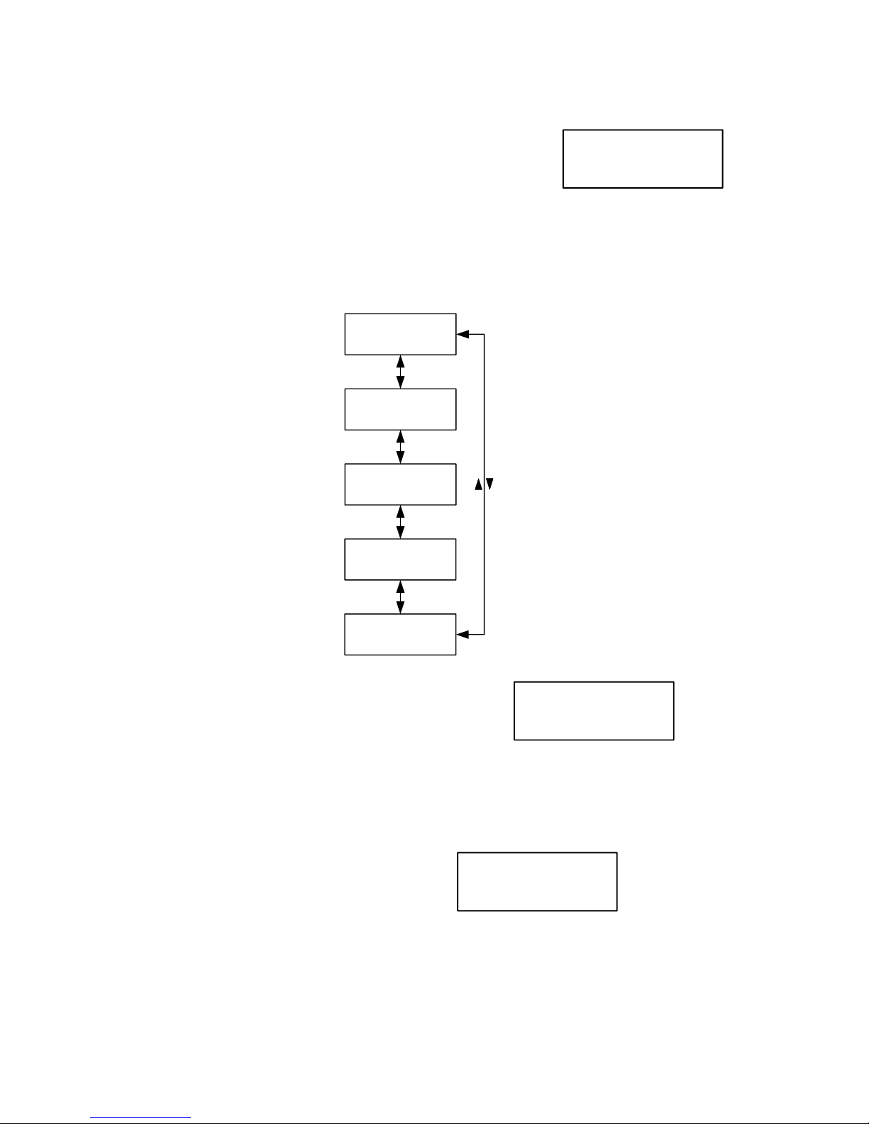
Temperature Compensation Status
This screen shows the Temperature compensation status:
The temperature compensation data is displayed thus:-
First line: Temperature, this is measured by a probe located
between the two standby batteries
Second and third line: Actual charging voltage being delivered to the battery, internally within the PSU.
Fourth line: Ideal charging voltage, the test set has a mathematical model of the ideal theoretical voltage that
should be used to charge the batteries at any given temperature. The actual measured voltage should be
between +/- 70millivolts of the displayed actual voltage for maximum battery performance.
NOTE: In this way the screen display can be used for checking that the battery is being charged correctly
between specified limits. The sample screen shot is an actual reading taken off a real, randomly selected PSU,
the actual and ideal voltages should track between these limits with temperature and will not necessarily be
identical as shown.
Fault Log
The fault log records all fault events that have occurred since the log was cleared:
A list of 11 fault events are shown below:
1. SMPS Fault: Switched Mode Power Supply internal low voltage fault,
supply is less than 20V.
2. PSU over 32V and PSU shutdown: Over-voltage fault and subsequent shutdown.
3. O/P1 fuse fault: Output 1 fuse fault.
4. O/P2 fuse fault: Output 2 fuse fault.
5. PSU under minimum battery charging voltage fault: Inability to correctly charge the battery
because voltage is too low fault.
6. PSU not charging battery fault: Charging circuit malfunction fault.
7. Battery lead disconnected fault: One or both batteries are disconnected.
8. Battery high resistance fault: Battery impedance greater than 177millohm limit when being load
tested.
9. Battery 1 under 11.5V fault: Battery 1 low voltage fault.
10. Battery 2 under 11.5V fault: Battery 2 low voltage fault.
11. Battery under 22V while charging fault: Catastrophic battery fault where total battery voltage is less
than 22 volts when charging is applied.
The log is scrolled through by pressing the ‘down’ key and the log events will be displayed in chronological
order, most recent displayed first. When the end of the log is reached this message “-----End of Log----“ will
be displayed.
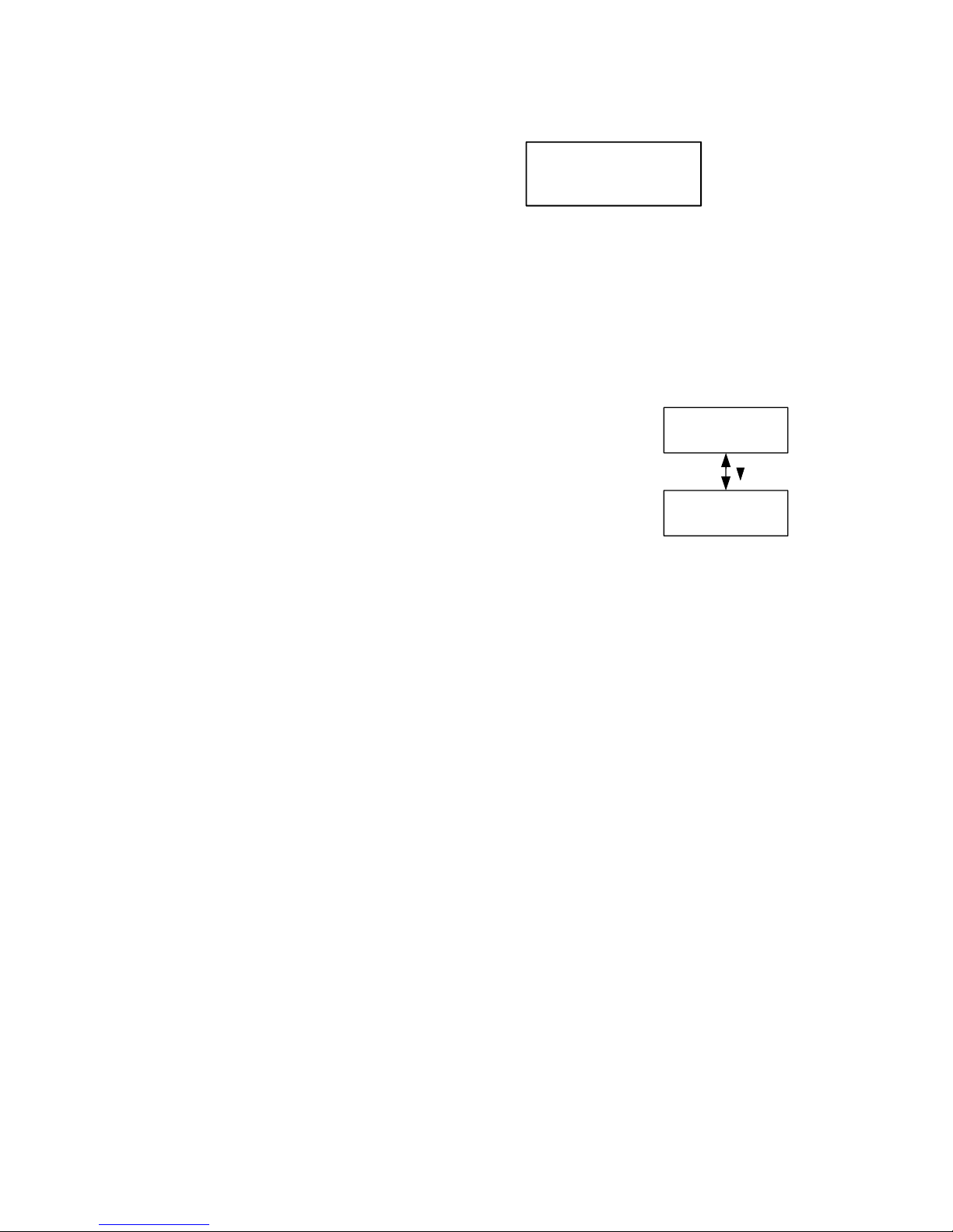
If the log is empty, ‘No faults logged’ will be displayed when attempting to view the log:
Multiple events of one type will only be appear once in the log to prevent the log from overfilling.
Erase Fault Log
This menu erases the current log enabling fresh events to be recorded. When ‘enter’ is pressed the log will be
erased and the display will show: ‘log erased’
Calibration
The calibration menu allows on-site calibration of the PSU. All PSUs are calibrated at the factory as a part of
their automated test procedure and normally do not require calibrating for the rest of their service lifetime.
However in extreme circumstances, e.g. operating in extremes of temperature, recalibration can be worthwhile.
Temperature = 31.0C
Charging Voltage:
Actual = 26.90V
Ideal = 26.90V+/-0.07V
Press down key to
scroll through faults
O/P1 fuse fault

Page 10 of 10 D2330-060116-V1.1
Calibrate Charging
Voltage
Calibration Voltage
Calibrate Battery
Current Monitor
Disconnect BAT1
Calibration Voltage
Calibrate Output 1
Current Monitor
Test Will Pulse O/P!
Calibration Voltage
Calibrate Output 2
Current Monitor
Test Will Pulse O/P!
Calibration Voltage
Calibrate Charging Voltage
When ‘enter’ is pressed the display will show:
‘Calibration Done’
After a short pause this display will be replaced with:
This display is described under the Temperature Compensation status section.
Note: There is a ‘hidden”’Advanced Information screen that can be accessed by pressing the ‘down’ arrow.
This information is useful only to trained technicians.
Calibrate Battery Current Monitor
Before calibrating, battery 1 must be disconnected as prompted. If the battery is not disconnected then
‘Disconnect Battery!’ will be displayed and the procedure will have to be started all over again.
When the calibration is completed successfully the display will show:
‘Calibration Done’
Note: There is a ‘hidden”’Advanced Information screen that can be accessed by pressing the ‘down’ arrow.
This information is useful only to trained technicians.
‘Calibrate Output 1’
When ‘enter’ is pressed the display will show:
‘Calibration Done’
Note: There is a ‘hidden”’Advanced Information screen that can be accessed by pressing the ‘down’ arrow.
This information is useful only to trained technicians.
‘Calibrate Output 2’
Please see above.
Temperature = 31.0C
Charging Voltage:
Actual = 26.90V
Ideal = 26.90V+/-0.07V
Table of contents