manuals.online logo
Brands
  1. Home
  2. •
  3. Brands
  4. •
  5. Dynabrade
  6. •
  7. Tools
  8. •
  9. Dynabrade 51400 Guide

Dynabrade 51400 Guide

PD20-14
October, 2020
Supercedes PD15.07
Safety, Operation and Maintenance – Save This Document and Educate All Personnel
BUFFER
WARNING
Read and understand this tool manual before operating your air tool. Follow all safety rules for the protection of operating personnel as
well as adjacent areas. Always operate, inspect and maintain this tool in accordance with the American National Standards Institute (ANSI).
Safety Requirements for the Use, Care and Protection of Abrasive Wheels – ANSI B7.1, and Safety Requirements for Abrading Materials
with Coated Abrasive Systems – ANSI B7.7, Compressed Air and Gas Institute (CAGI) Safety Code for Portable Air Tools – B186.1, Code of
Federal Regulation – CFR 29 Part 1910, International Organization for Standardization (ISO) Hand Held Non-Electric Power Tools – Safety
Requirements ISO 11148 series and applicable State and Local Regulations.
Find The Most Current Offering of Support Documents and Accessories at www.Dynabrade.com
Read and understand tool manual before work starts
to reduce risk of injury to operator, visitors, and tool.
Ear protection to be worn when exposure to sound,
exceeds the limits of applicable Federal, State or
local statues, ordinances and/or regulations.
Practice safety requirements.Work alert, have proper
attire, and do not operate tools under the influence
of alcohol or drugs.
Air line hazard, pressurized supply lines and flexible
hoses can cause serious injury. Do not use damaged,
frayed or deteriorated air hoses and fittings.
Eye protection must be worn at all times, eye
protection to conform to ANSI Z87.1.
Respiratory protection to be used when exposed to
contaminants that exceed the applicable threshold
limit values required by law.
Some dust created by sanding, grinding, drilling, and other construction activities contain chemicals known to cause cancer, birth defects
or other reproductive harm. Some examples of these chemicals are:
• Lead from lead-based paints
• Crystalline silica from bricks and cement and other masonry products
• Arsenic and chromium from chemically treated lumber
Your risk from these exposures varies, depending on how often you do this type of work. To reduce your exposure to these chemicals: work in a well
ventilated area, and work with approved safety equipment, such as those dust masks that are specially designed to filter out microscopic particles.
DO NOT USE Tool for Anything Other Than Its Intended Applications.
Training: Proper care, maintenance, and storage of your air tool will maximize tools performance and reduce chance for accident.
Employer's Responsibility: Provide operators with safety instructions and training for safe use of tools and accessories.
Report to Your Supervisor any Condition of the Tool, Accessories or Operation you Consider Unsafe.
SAFETY and OPERATING INSTRUCTIONS
Carefully Read and Understand the General
and Grinder sections found in Tool Safety and
Operating Guidelines (PN00001676) Before
Handling or Using Tool.
Carefully Read all instructions before operating or servicing
any Dynabrade
®
Abrasive Power Tool. Products offered by
Dynabrade are not to be modified, converted or otherwise
altered from the original design.
.4 hp, 7°, Rear Exhaust
Buffer
Model Buffer
Diameter Power RPM Spindle
Thread Exhaust
51400
3" (76 mm)
.4 hp
3,200
3/8"- 24
Rear
51401 5,000
51403 5,000 Rear
w/94533 Muffler
51430 4"-5" (127 mm) 3,200 Rear
LIFETIME WARRANTY
To validate Dynabrade Lifetime Warranty, you must register each tool at: www.dynabrade.com. Registration of each tool at website
is required. Dynabrade will not honor Lifetime Warranty on unregistered tools. Please view the entire Lifetime Warranty Policy at:
www.dynabrade.com.
Models
51400:
3", 3,200 RPM
51401:
3", 5,000 RPM
51403:
3", 5,000 RPM, w/94533 Muffler
51405:
Versatility Kit
51430:
4"-5", 3,200 RPM
.4 hp, 7˚, Rear Exhaust Buffer
Air Motor and Machine Parts
ITEM P/N DESCRIPTION QTY.
150126
50147
Back up Pad - 3"
Back-Up Pad - 4"-5" 1
250781 Rear Exhaust Cover 1
350782 Adapter 1
454552 Bearing 2
554472 Gear Shaft 2
606213
54519
5,000 RPM Gear
3,200 RPM Gear 2
750786
50787
3,200 RPM Planetary Carrier
5,000 RPM Planetary Carrier 1
854468 Ring Gear 1
950778 Spacer 1
10 02649 Bearing 1
11 54529 Shim (3/pkg.) 1
12 01478 Front End Plate 1
13 50767 Pin 2
14 01479 Spacer 1
15 54553
54554
5,000 RPM Rotor
3,200 RPM Rotor 1
16 01480 Blade (4/pkg.) 1
17 01476 Cylinder 1
18 02673 Rear Bearing Plate 1
19 02696 Bearing 1
20 02679 Shield 1
21 01041 Grease Fitting 1
22 50784 Set Screw 1
23 50776 Motor Housing 1
24 01548 Gasket 1
25 01461 Lock Nut 1
26 01558 Collar 1
27 95523 O-Ring 1
28 01470 Insert 1
29
02100
02101
02102
Housing - 51400
Housing - 51401
Housing - 51430
1
30 01950 Safety Lock Lever 1
31 12132 Pin 1
32 95558 Retaining Ring 1
33 01449 Valve Stem 1
34 95730 O-Ring 1
35 01024 O-Ring 1
36 01469 Speed Regulator Assembly 1
37 01464 Seal 1
38 01472 Tip Valve 1
39 01468 Spring 1
40 01564 Air Control Ring 1
41 95711 Retaining Ring 1
42 95438 O-Ring 1
43 94521 Muffler Base 1
44 94528 Felt Muffler 1
45 94522 Muffler Cap 1
46 95375 O-Ring 1
47 94526 Spacer 1
48 94523 Inlet Adapter 1
49 94519 Muffler Assembly 1
50 94534 Thinsulate™ Muffler 1
51 94525 Felt Silencer 1
52 94527 Inlet Adapter 1
53 94533 Muffler Assembly
(Model 51403 ONLY) 1
2
1
2
6
5
7
9
10
13
14
15
17
13
18
19
20
4
4
A8
A8G1
O1
A2
G1
1112
28 N•m
T
17 N•m
T
3
22
16 8
21
23
41 42 43 44 45
45
46
46
47
47
49
A8
A8
O1
23 N•m
T
23 N•m
T
O1
48
53
26
27 28
33
32
30* 31
37 38
39
36
34
35
A829 40
Left Hand Threads
A8
24
45 N•m
T
25
51 52
41
42 43
50
Right Hand Threads
Always follow adhesive manufacturers
cleaning and priming recommendations.
Adhesive: A2= Loctite #271
A6= Loctite #380
A8= Loctite #567
Torque: N•m x 8.85 = In. - lbs.
Oil: O1= Air Lube
O
A
T
KEY
IMPORTANT OPERATING,
MAINTENANCE AND SAFETY
INSTRUCTIONS:
Carefully read all instructions before operating or servicing any
Dynabrade®Abrasive Power Tool.
WARNING: Hand, wrist and arm injury may result from repetitive work
motion and overexposure to vibration.
IMPORTANT: All Dynabrade Rotary Vane air tools must be used with a
Filter-Regulator-Lubricator to maintain all warranties.
OPERATING INSTRUCTIONS:
WARNING: Eye, face, respiratory, sound and body protection must be worn
while operating power tools. Failure to do so may result in serious
injury or death. Follow safety procedures posted in workplace.
1. With power source disconnected from tool, securely fasten
abrasive/accessory on tool.
2. Install air fitting into inlet bushing of tool. IMPORTANT: Secure inlet bush-
ing of tool with a wrench before attempting to install the air fitting
to avoid damaging valve body housing.
3. Connect power source to tool. Be careful not to depress
throttle lever in the process.
4. Check tool speed with tachometer. If tool is operating at a higher
speed than the RPM marked on the tool or operating improperly,
the tool should be serviced to correct the cause before use.
MAINTENANCE INSTRUCTIONS:
1. Check tool speed regularly with a tachometer. If tool is operating at
a higher speed than the RPM marked on the tool, the tool should be
serviced to correct the cause before use.
2. Some silencers on air tools may clog with use.
Clean and replace as required.
3. All Dynabrade Rotary Vane air motors should be lubricated.
Dynabrade recommends one drop of air lube per minute for each 10
SCFM (example: if the tool specifications state 40 SCFM, set the drip rate
of your filter-lubricator at 4 drops per minute). Dynabrade Air Lube
(P/N 95842: 1 pt. 473 ml.) is recommended.
4. It is strongly recommended that all Dynabrade rotary vane air tools be
used with a Filter-Regulator-Lubricator to minimize the possibility of
misuse due to unclean air, wet air or insufficient lubrication.
Dynabrade recommends the following: 11405 Air Line Filter-Regulator-
Lubricator—Provides accurate air pressure regulation, two-stage filtration
of water contaminants and micro-mist lubrication of pneumatic
components. Operates 40 SCFM @100 PSIG has 3/8" NPT female ports.
5. Lubricate planetary gears through the grease fitting with 2 plunges for
every 50 hours of use, to achieve maximum gear life (order 95542 Grease
and 95541 Gun).
6. Use only genuine Dynabrade replacement parts. To reorder replacement
parts, specify the Model #, Serial # and RPM of your machine.
7. A Motor Tune-Up Kit (P/N 96174) is available which includes assorted
parts to help maintain motor in peek operating condition. Please refer to
Dynabrade’s Preventative Maintenance Schedule for a guide to expectant
life of component parts.
8. Mineral spirits are recommended when cleaning the tool and parts.
Do not clean tool or parts with any solvents or oils containing acids,
esters, keytones, chlorinated hydrocarbons or nitro carbons.
SAFETY INSTRUCTIONS:
PRODUCTS OFFERED BY DYNABRADE
SHOULD NOT BE CONVERTED OR OTHERWISE
ALTERED FROM ORIGINAL DESIGN WITHOUT
EXPRESSED WRITTEN CONSENT FROM DYNABRADE, INC.
• IMPORTANT: User of tool is responsible for following accepted safety
codes such as those published by the American National Standards
Institute (ANSI).
• Operate machine for one minute before application to workpiece to
determine if machine is working properly and safely before work begins.
• Always disconnect power supply before changing abrasive/accessory or
making machine adjustments.
• Inspect abrasives/accessories for damage or defects prior to
installation on tools.
• Please refer to Dynabrade’s Warning/Safety Operating Instructions Tag
(Reorder No. 95903) for more complete safety information.
• WARNING: Hand, wrist and arm injury may result from repetitive work,
motion and overexposure to vibration.
NOTICE
All Dynabrade motors use the highest quality parts and metals available and
are machined to exacting tolerances. The failure of quality pneumatic
motors can most often be traced to an unclean air supply or the lack of
lubrication. Air pressure easily forces dirt or water contained in the air supply
into motor bearings causing early failure. It often scores the cylinder walls
and the rotor blades resulting in limited efficiency and power. Our warranty
obligation is contingent upon proper use of our tools and cannot apply to
equipment which has been subjected to misuse such as unclean air,
wet air or a lack of lubrication during the use of this tool.
MOTOR ASSEMBLY/DISASSEMBLY
INSTRUCTIONS
Important: Manufacturer’s warranty is void if tool is disassembled before
warranty expires.
NOTICE: Dynabrade strongly recommends the use of their 52296 Repair
Collar (sold separately) during assembly/disassembly activities.
Failure to use this collar will highly increase the risk of damage
to the valve body of this tool. Please refer to parts breakdown for
part identification.
MOTOR DISASSEMBLY:
1. Disconnect tool from power source.
2. Secure air tool in vise using 52296 Repair Collar. Remove back-up pad.
3. With an adjustable pin wrench or 50971 Lock Ring Tool, remove 50781
Rear Exhaust Cover by turning counter-clockwise.
4. Remove 50784 Set Screw and pull 50782 Adapter and planetary
carrier assembly from 50776 Housing.
5. Press planetary carrier assembly from rear 54552 Bearing.
Remove ring gear and gears from 50786 or 50787 Planetary Carrier.
6. Secure planetary carrier in vise and remove 50782 Adapter.
Press carrier from front 54552 Bearing.
7. Grab onto pinion and pull motor assembly from motor housing.
Remove 50778 Spacer.
8. Press 54553 or 54554 Rotor from 02673 Rear Bearing Plate. Press 02696
Rear Bearing from rear bearing plate, remove 02679 Shield.
9. Remove cylinder and rotor blades from rotor.
10. Press 54553 or 54554 Rotor through 02649 Front Bearing and 01478
Front Bearing Plate.
MOTOR DISASSEMBLY COMPLETE.
VALVE BODY DISASSEMBLY:
1. Position valve body in vise using 52296 Repair Collar w/air inlet facing up.
2. Remove air fitting by securing 94523 Inlet Adapter with a wrench
and twist air fitting from inlet adapter.
IMPORTANT: 94523 Inlet Adapter must be secured before attempting
to removeair fitting to avoid damaging valve body housing.
3. Remove 94523 Inlet Adapter.
4. Remove 95711 Retaining Ring from inlet adapter and separate
94521 Muffler Base from 94522 Muffler Cap. Remove sintered
muffler and felt muffler.
5. Remove 01564 Air Control Ring from valve body. Using needle nose
pliers, remove 01468 Spring, 01472 Tip valve and 01464 Seal.
6. Using a 2.5mm drift pin, tap 12132 Pin from housing and remove
throttle lever.
7. Remove 95558 Retaining Ring. Push 01469 Regulator from valve body
and remove o-rings.
VALVE DISASSEMBLY COMPLETE.
MOTOR ASSEMBLY:
IMPORTANT: Be sure parts are clean and in good repair before
assembling. Follow all grease, oil, and torque specifications.
1. Slip 01479 Spacer onto 54553 or 54554 Rotor.
2. Place a .002" Shim into 01478 Front Bearing Plate for initial spacing.
Then slip 02649 Bearing into 01478 Front Bearing Plate.
Press assembly onto rotor.
3. Check the clearance between rotor and bearing plate by using a .001"
feeler gauge. Clearance should be at .001" to .0015". Adjust clearance by
repeating steps 1-3 changing shims as required.
4. Once proper rotor gap clearance is achieved, install lubricated blades into
rotor slots, (use 95842 Dynabrade Air Motor Oil or equivalent).
5. Install 01476 Cylinder so it rests against the 01478 Front Bearing Plate,
(make sure inlet holes of cylinder line up with inlet holes in 02673 Rear
Bearing Plate.
6. Press 02696 Bearing into 02673 Rear Bearing Plate. Press this
assembly onto rotor. Important: Fit must be snug between bearing plates
and cylinder. If too tight, rotor will not turn freely. Rotor must then be lightly
tapped at press end so it will turn freely while still maintaining a snug fit. A
loose fit will not achieve the proper preload or motor bearings. Next, place
a small amount of grease on the 02696 Bearing and stick 02679 Shield
against the bearing.
7. Secure housing in vise using 52296 Repair Collar or padded jaws so that
motor cavity points upward.
8 Install motor assembly into housing, making sure motor drops all the way
into housing.
9. Install 50778 Spacer so that flat side rests against 02649 Bearing.
10. Press front 54552 Bearing onto front end of 50786 or
50787 Planetary Carrier.
11. Hold planetary carrier in a soft jaw vise and apply one drop of #271
Loctite®to the threads of 50782 Adapter. Install adapter onto planetary
3
carrier. Torque to 17 N-m/150 in. lbs.
12. Install planetary gears and 54472 Gear Shafts onto planetary housing.
13. Slip 54468 Ring Gear over gears making sure that notches in ring
gear will align with lock screw and grease fitting in 50776 Housing
once planetary gear assembly is installed.
14. Press rear 54552 Bearing onto 50786 or 50787 Planetary Carrier,
until the outer race of the bearing touches the ring gear.
15. Slip the complete planetary gear assembly into 50776 Housing and
install 50784 Lock Screw.
16. Install 50781 Rear Exhaust Cover onto 50776 Housing.
Use 50971 Lock Ring Tool, torque to 28 N-m/250 in. lbs.
17. Lubricate planetary gears through 01041 Grease Fitting
with two plunges every 50 hours of use for maximum gear life.
18. Install back-up pad.
VALVE BODY ASSEMBLY:
1. Insert 01469 Regulator with o-rings and valve stem in place into valve
body. Secure with 95558 Retaining Ring.
2. Secure valve body in vise using 52296 Repair Collar with air inlet
facing upwards. Insert 01464 Seal.
3. Line up hole in valve stem with hole in housing (looking past brass
bushing). Insert 01472 Tip Valve so that the metal pin passes through the
hole in the valve stem. Install 01468 Spring (small end towards tip valve).
4. Roll 94528 Felt Muffler and place into 94522 Muffler Cap. I
nstall 94521 Muffler Base onto muffler cap.
5. Install 95438 O-Ring into groove on muffler base. Place 95375 O-Ring
and 94526 Spacer into recessed area of muffler cap.
6. Slip 94523 Inlet Adapter through muffler assembly and install 95711
Retainer Ring into groove on inlet adapter.
7. Install 01564 Air Control Ring into valve body housing.
8. Apply Loctite #567 PST Pipe Sealant to threads of 94523 Inlet Adapter and
install entire muffler assembly onto valve body (torque 23.0 N•m/200 in. - lbs.).
9. Replace air fitting.
Secure inlet adapter with a wrench before tightening air fitting.
10. Install throttle lever and 12132 Pin.
TOOL ASSEMBLY COMPLETE.
PLEASE ALLOW 30 MINUTES FOR ADHESIVES TO
CURE BEFORE OPERATING TOOL.
NOTICE: To adjust throttle body orientation for a rear exhaust tool:
1. Use 52296 Repair Collar to secure valve body in vise with
50776 Housing facing up.
2. Peel down 01558 Collar to expose the hex portion of 01461 Lock Nut.
3. Using a 34mm crows foot and firmly holding motor housing, turn 01461
Lock Nut counter clockwise to loosen assembly.
4. Adjust orientation of the throttle lever to agree with your grip and
comfort level allowing for additional rotation due to torquing.
5. Using the 34mm crows foot and a torque wrench set to 400 lb. in.,
(while firmly holding motor housing in place to reduce housing rotation)
tighten 01461 Lock Nut.
IMPORTANT: Motor should now be tested for proper operation at 90 PSIG.
If motor does not operate properly or operates at a higher RPM than marked
on the tool, the tool should be serviced to correct the cause before use. Before
operating, place 2-3 drops of Dynabrade Air Lube (P/N 95842) directly into air
inlet with throttle lever depressed. Operate tool for 30 seconds to determine if
tool is operating properly and to allow lubricating oils to properly penetrate motor.
Loctite
®
is a registered trademark of Loctite Corp.
DYNABRADE, INC. www.dynabrade.com
8989 Sheridan Drive
•
Clarence, NY 14031-1419
•
Phone: (716) 631-0100
•
Fax: 716-631-2073
•
International Fax: 716-631-2524
© DYNABRADE, INC., 2020
REFERENCE CONTACT INFORMATION
American National Standards Institute (ANSI)
www.ansi.org
Compressed Air & Gas Institute (CAGI)
www.cagi.org
European Committee for Standardization (PNEUROP)
www.pneurop.org
International Organization of Standards (ISO)
www.iso.org
U.S. Government Publishing Office (GPO)
www.gpo.gov
OPTIONAL ACCESSORIES
MACHINE SPECIFICATIONS
Additional Specifications: Air Inlet Thread 1/4" NPT • Hose I.D. 3/8" (10 mm) ● Visit dynabrade.com for your model’s current vibration and sound data.
Motor Tune-Up Kit
Part No. 96174
•
Includes assorted
parts to help maintain
and repair motor.
Open-End Wrench
Part No. 95262 – 14mm open-end.
Repair Collar
Part No. 52296
•
Specially designed collar for use in vise
to prevent damage to valve body
housing during disassembly/assembly.
50971 Lock Ring Tool
•
Lock Ring Tool has a 3/8 in. square socket
for use with 3/8 in. drive; breaker bar,
ratchet head, or torque wrenches.
Finesse Sanding Creme
Part No. 95723: 4 oz. (118 ml).
Part No. 95724: 1 qt. (946 ml).
Part No. 95725: 1 gal. (3.8 L).
•
A sanding compound for metal,
fiberglass and composites.
Use with fine-grade sanding
discs.
Dynabrade Glaze
•
For use with slow-speed
tools to achieve a high
gloss after compounding.
Part No. 95727: 4 oz. (118 ml).
Part No. 95728: 1 qt. (946 ml).
3" diameter
5" diameter
90040
“Flat-Face” Foam Buffs
•
Velcro-backed for easy
attachment/removal.
•
Excellent absorption of
excess compound/glaze.
•
Prevents swirls.
•
Two sizes to choose from:
3"– 90038
•
Use with models 51400.
5"– 90040
•
Use with models 51430, 7° Buffer.
90038
Dynaswivel
®
(1/4" NPT)
Part No. 94300
•
Patented “universal-joint” connects
portable air tools to an air line.
•
Swivels 360° AT TWO PIVOT POINTS
allowing the air hose to drop directly
to the floor while providing superb
tool handling.
•
New lightweight, non-marring composite
construction; industrial quality.
Terry Cloth
Synthetic Wool
3" diameter
90027
3" diameter
90029
Grease 10 oz.
Part No. 95542
•
Multi-purpose grease for all
types of bearings, cams, gears.
•
High film strength; excellent
resistance to water, steam, etc.
•
Workable range 0˚ F to 300˚ F.
Push-type Grease Gun
Part No. 95541
•
One-hand operation.
Model Speed Power Sound Level Air Consumption Pad Diameter Spindle Thread Weight Length Height
51400 3,200 RPM
.4 hp
(298 W)
80 dB(A)
24 SCFM
(680 LPM)
3" (76 mm)
3/8"-24 Male
1.7 lbs.
(.8 kg)
8-3/4"
(222 mm)
4-1/4"
(108 mm)
51401/51403 5,000 RPM 78 dB(A)
51430 3,200 RPM 80 dB(A) 4"-5"
(102-107mm)
2.4 lbs.
(1.1 kg)
9-3/4"
(248 mm)
4-1/2"
(114 mm)

This manual suits for next models

3

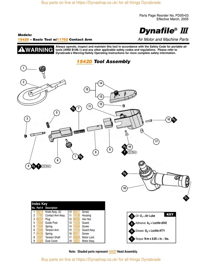
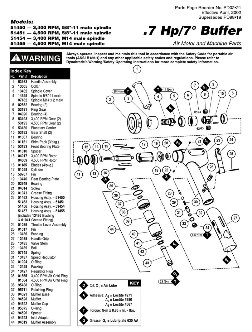
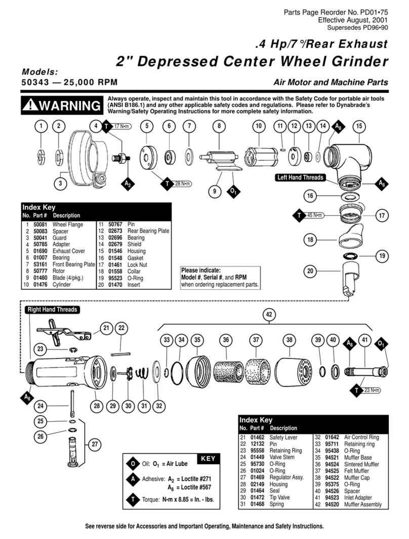
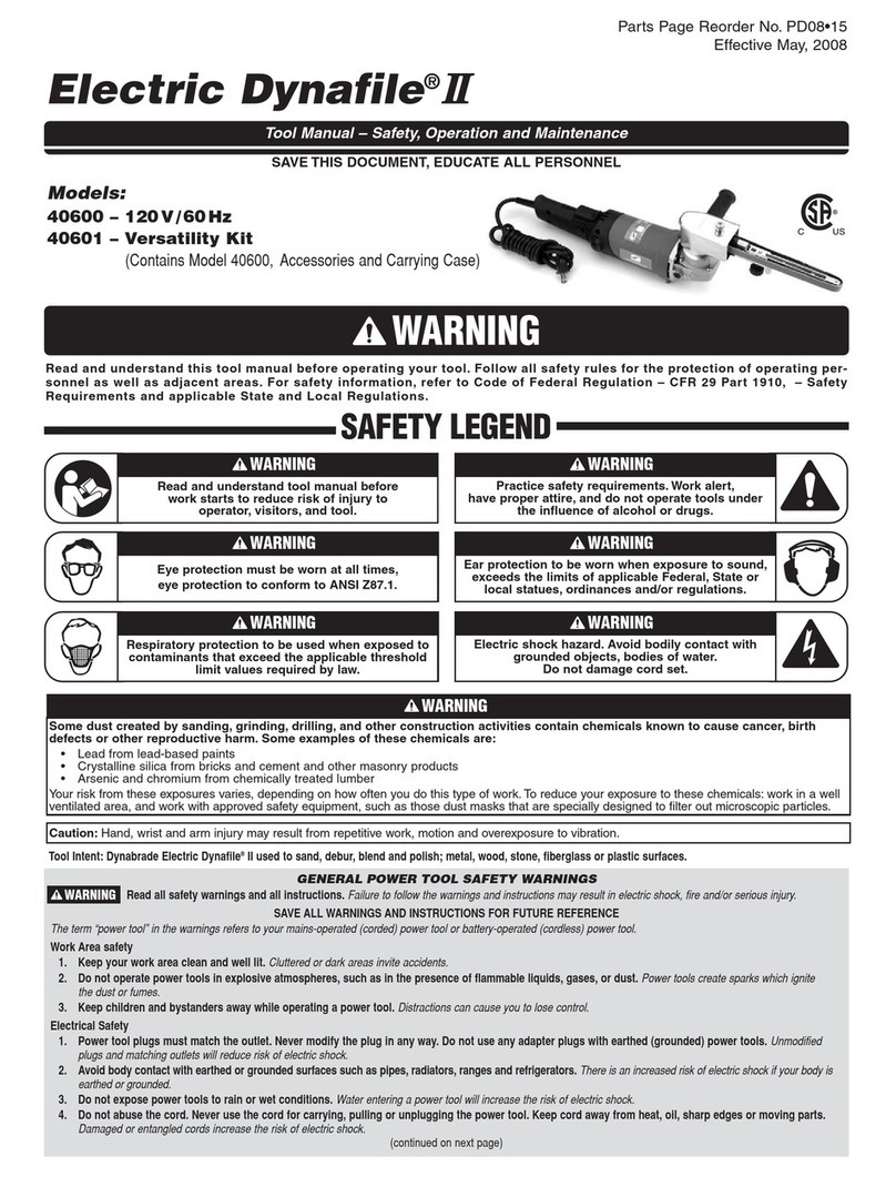
Other Dynabrade Tools manuals

Dynabrade 50343 User manual

Dynabrade

Dynabrade 50343 User manual

Dynabrade 40600 Guide

Dynabrade

Dynabrade 40600 Guide

Dynabrade DynaZip 13280 Guide

Dynabrade

Dynabrade DynaZip 13280 Guide

Dynabrade 13450 Guide

Dynabrade

Dynabrade 13450 Guide

Dynabrade AutobradeRed DynaZip 18255 User manual

Dynabrade

Dynabrade AutobradeRed DynaZip 18255 User manual

Dynabrade 52573 User manual

Dynabrade

Dynabrade 52573 User manual

Dynabrade 40610 Manual

Dynabrade

Dynabrade 40610 Manual

Dynabrade 53472 User manual

Dynabrade

Dynabrade 53472 User manual

Dynabrade Dynafile III User manual

Dynabrade

Dynabrade Dynafile III User manual

Dynabrade 40352 User manual

Dynabrade

Dynabrade 40352 User manual

Dynabrade 51450 User manual

Dynabrade

Dynabrade 51450 User manual

Dynabrade Auto File II 18100 Guide

Dynabrade

Dynabrade Auto File II 18100 Guide

Dynabrade Dynabug II Guide

Dynabrade

Dynabrade Dynabug II Guide

Dynabrade Electric Dynafile II User manual

Dynabrade

Dynabrade Electric Dynafile II User manual

Dynabrade 95809 User manual

Dynabrade

Dynabrade 95809 User manual

Dynabrade 52280 User manual

Dynabrade

Dynabrade 52280 User manual

Dynabrade Dynafile 14000 Guide

Dynabrade

Dynabrade Dynafile 14000 Guide

Dynabrade 50340 User manual

Dynabrade

Dynabrade 50340 User manual

Dynabrade 18050 User manual

Dynabrade

Dynabrade 18050 User manual

Popular Tools manuals by other brands

Tyco Electronics 411-15684 instruction sheet

Tyco Electronics

Tyco Electronics 411-15684 instruction sheet

Hirose HT601/TM21P-88P instruction manual

Hirose

Hirose HT601/TM21P-88P instruction manual

DOGA XS-38D Service manual

DOGA

DOGA XS-38D Service manual

Texi Zorro 110 Free Operation manual

Texi

Texi Zorro 110 Free Operation manual

Beta 1461/C32G Operation manual and instructions

Beta

Beta 1461/C32G Operation manual and instructions

Beta 960KPC Operation manual and instructions

Beta

Beta 960KPC Operation manual and instructions

Tiger Tool 10910 manual

Tiger Tool

Tiger Tool 10910 manual

LIBRETTO V659 manual

LIBRETTO

LIBRETTO V659 manual

Scell-it GAMME PREMIUM E-640RA user manual

Scell-it

Scell-it GAMME PREMIUM E-640RA user manual

Sealey VS911.V3 instructions

Sealey

Sealey VS911.V3 instructions

Global Industrial 641767 instruction manual

Global Industrial

Global Industrial 641767 instruction manual

Faicom A Use and maintenance manual

Faicom

Faicom A Use and maintenance manual

Silverline 486869 quick start guide

Silverline

Silverline 486869 quick start guide

Cornwell Tools CAT5500HD operating instructions

Cornwell Tools

Cornwell Tools CAT5500HD operating instructions

Fein BF10-280ET instruction manual

Fein

Fein BF10-280ET instruction manual

Welbilt 1971202 user manual

Welbilt

Welbilt 1971202 user manual

Wen 61711 user manual

Wen

Wen 61711 user manual

tormek SVM-45 manual

tormek

tormek SVM-45 manual

manuals.online logo
manuals.online logoBrands
  • About & Mission
  • Contact us
  • Privacy Policy
  • Terms and Conditions

Copyright 2025 Manuals.Online. All Rights Reserved.