Dynacord DPC 8000 User manual

DPC 8000
en |


Table of contents
1Safety notes 4
2Brief description 6
3System overview 7
4Scope of delivery and warranty 8
5Installation 9
5.1 Top 9
5.2 Bottom 11
5.3 Delivery condition 12
5.4 Button labeling 13
5.5 Retrofit options 13
5.5.1 Alarm button (EB DPC) 13
5.5.2 Key switch (NRS 90231) 14
6Activation 16
6.1 PCA BUS interface 16
6.1.1 Interface description 16
6.2 LINE interface 17
6.3 MIC interface 17
6.4 EXT interface 18
7Configuration 19
7.1 User menu 21
7.2 Setup menu 22
8Operation 24
8.1 Indicators 24
8.2 Functions 25
9Maintenance 29
10 Technical data 30
10.1 Block diagram 31
10.2 Dimensions 32
10.3 Standards 32
11 Appendix 34
11.1 CAN bus basics 34
11.2 Call station extension 34
DPC 8000 Table of contents | en 3
28-Feb-2013 | |

Safety notes
Danger!
The lightning symbol inside a triangle notifies the user of high-voltage, uninsulated lines and
contacts inside the devices that could result in fatal electrocution if touched.
!
Warning!
An exclamation mark inside a triangle refers the user to important operating and service in-
structions in the documentation for the equipment.
1. Read these safety notes.
2. Keep these safety notes in a safe place.
3. Heed all warnings.
4. Observe all instructions.
5. Do not operate the device in close proximity to water.
6. Use only a dry cloth to clean the unit.
7. Do not cover any ventilation slots. Always refer to the manufacturer's instructions when
installing the device.
8. Do not install the device close to heaters, ovens, or other heat sources.
9. Note: The device must only be operated via the mains power supply with a safety ground
connector. Do not disable the safety ground connection function of the supplied power
cable. If the plug of the supplied cable does not fit your mains socket, please contact
your electrician.
10. Ensure that it is not possible to stand on the mains cable. Take precautions to ensure the
mains cable cannot become crushed, particularly near the device connector and mains
plug.
11. Only use accessories/extensions for the device that have been approved by the
manufacturer.
12. Unplug the device if there is risk of lightning strike or in the event of long periods of
inactivity. However, this does not apply if the device is to be used as part of an
evacuation system!
13. Have all service work and repairs performed by a trained customer service technician.
Service work must be carried out immediately following any damage such as damage to
the mains cable or plug, if fluid or any object enters the device, if the device has been
used in rain or become wet, or if the device has been dropped or no longer works
correctly.
1
4en | Safety notes DPC 8000
28-Feb-2013 | |

14. Please ensure that no dripping water or spray can penetrate the inside of the device. Do
not place any objects filled with fluids, such as vases or drinking vessels, on top of the
device.
15. To ensure the device is completely free of voltage, unplug the device from the power
supply.
16. When installing the device, ensure that the plug is freely accessible.
17. Do not place any sources of open flame, such as lit candles, on top of the device.
18. This PROTECTION CLASS I device must be connected to a MAINS socket with a safety
ground connection.
Caution!
Use only manufacturer-approved carts, stands, brackets, or tables that you acquired together
with the device. When using carts to move the device, make sure the transported equipment
and the cart itself cannot tip over or cause injury or material damage.
IMPORTANT SERVICE INFORMATION
!
Caution!
This service information is for use by qualified service personnel only. To avoid the risk of
electric shock, do not perform any maintenance work that is not described in the operating
instructions unless you are qualified to do so. Have all service work and repairs performed by
a trained customer service technician.
1. Repair work on the device must comply with the safety standards specified in EN 60065
(VDE 0860).
2. A mains isolating transformer must be used during any work for which the opened device
is connected to and operated with mains voltage.
3. The device must be free of any voltage before performing any alterations with upgrade
sets, switching the mains voltage, or performing any other modifications.
4. The minimum distance between voltage-carrying parts and metal parts that can be
touched (such as the metal housing) or between mains poles is 3 mm, and must be
observed at all times.
5. The minimum distance between voltage-carrying parts and circuit parts that are not
connected to the mains (secondary) is 6 mm, and must be observed at all times.
6. Special components that are marked with the safety symbol in the circuit diagram (note)
must only be replaced with original parts.
7. Unauthorized changes to the circuitry are prohibited.
8. The protective measures issued by the relevant trade organizations and applicable at the
place of repair must be observed. This includes the properties and configuration of the
workplace.
9. Observe the guidelines with respect to handling MOS components.
Danger!
SAFETY COMPONENT (MUST BE REPLACED BY ORIGINAL PART)
DPC 8000 Safety notes | en 5
28-Feb-2013 | |

Brief description
The DPC 8015 is a call station for the PROMATRIX 8000 system. As standard, the call station
has a goose neck microphone with pop shield and permanent monitoring, a total of 20
buttons, an illuminated LC display, and an integrated loudspeaker. The call station can be
modified to suit the user’s requirements by connecting up to five DPC 8120 call station
extensions, each with 20 customizable function and speed dial buttons.
2
6en | Brief description DPC 8000
28-Feb-2013 | |

System overview
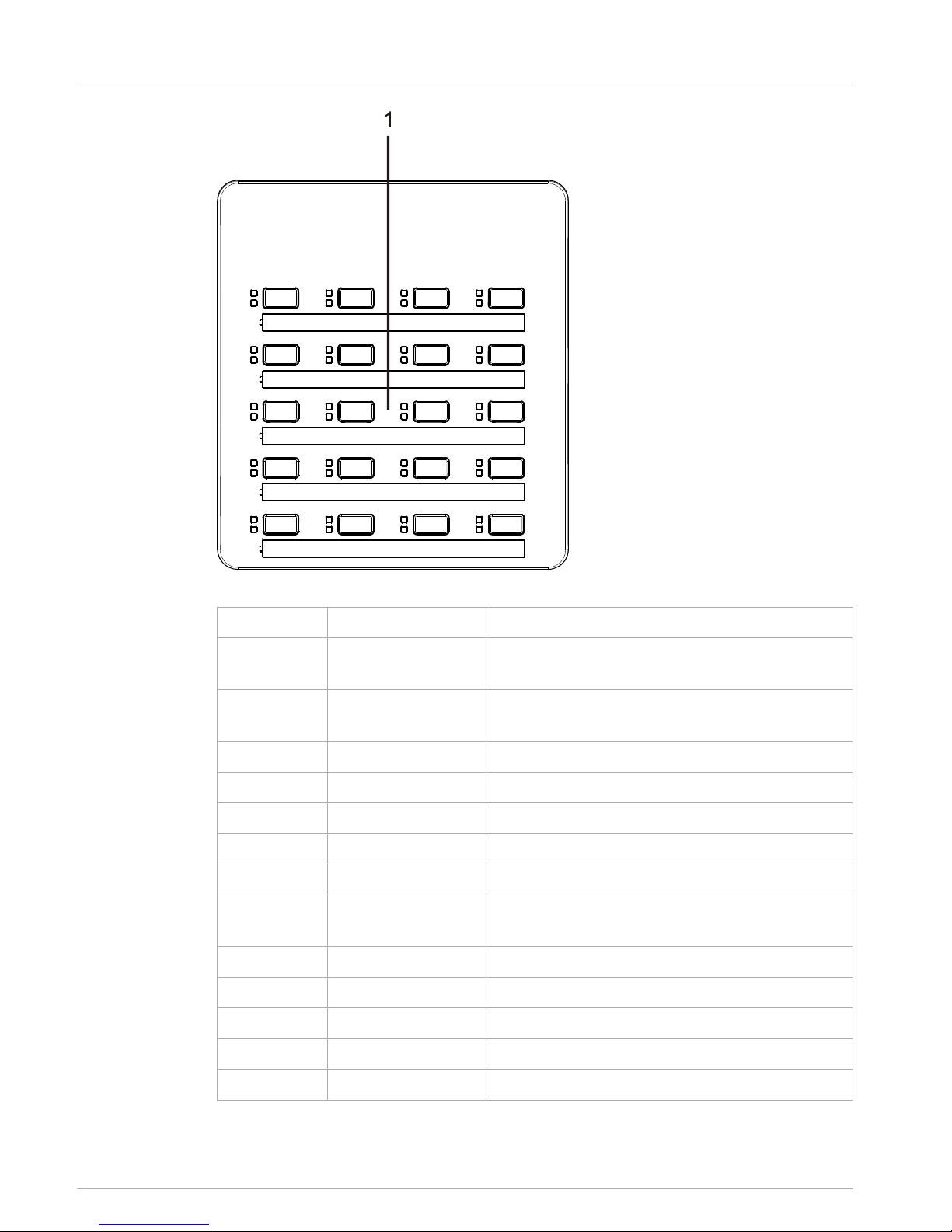
The PROMATRIX 8000 system includes the DPC 8015 call station and the DPC 8120 call
station extension. The call station is equipped with a goose neck microphone, and has 15
customizable selection and function buttons and five pre-programmed menu/function buttons.
Up to three alarm buttons or key switches can also be retrofitted. The call station is equipped
with an illuminated LC display (122 x 32 pixels). The call station has the following features:
• Microphone with preamplifier and compressor/limiter switch
• Function and selection buttons with programmable button assignment
• Simple labeling of buttons with labeling strips and format template (file in .doc format
included in the IRIS-Net scope of delivery)
• Possible to install covered alarm buttons or key switches (optional, three installation
slots)
• Possible to connect an external microphone or audio source
• Built-in loudspeaker
• High-resolution LC display
• Comprehensive parameter settings menu on the actual call station
• Microphone and line monitoring
• Error message via LED and buzzer, and error text in the LC display
• Processor control of all functions
• Monitoring of the processor system via watchdog circuit
• Non-volatile FLASH memory for configuration data
The call station is processor-controlled, and equipped with extensive monitoring functions. A
watchdog circuit is built in to monitor the processor system. The internal microphone can be
monitored for function, interruptions, and short-circuits. Line monitoring for the CAN bus and
for audio transmission allows line interruptions and short-circuits to be detected and
indicated to the user. The call stations for the PROMATRIX 8000 system can be configured
quickly and easily using IRIS-Net. A graphical and conversational user interface allows the user
to define all button functions, priorities, options, and other properties.
3
DPC 8000 System overview | en 7
28-Feb-2013 | |

Scope of delivery and warranty
Number Component
1 DPC 8015 Call Station
1 Patch cable (3 meters)
1 Operating instructions (this document)
1 Warranty card with safety notes
Table 4.1: DPC 8015 scope of delivery
Number Component
1 DPC 8120 Call Station Extension
1 6-pin connecting cable for call station extension
1 Connecting holder for call station extension
1 Connecting plate for call station extension
6 Screws (self-tapping)
1 Technical information
1 Warranty card with safety notes
Table 4.2: DPC 8120 scope of delivery
Warranty
For information regarding the warranty, see www.dynacord.com
4
8en | Scope of delivery and warranty DPC 8000
28-Feb-2013 | |

Installation
Top
Figure 5.1: DPC 8015
5
5.1
DPC 8000 Installation | en 9
28-Feb-2013 | |

Figure 5.2: DPC 8120
Number Element Description
1 Selection buttons Circuit and group selection buttons with green and
yellow LED.
2 Button installation
slots
For up to three optional alarm buttons or key
switches
3 POWER LED Illuminates green if the power supply is on
4 FAULT LED Illuminates yellow if an error occurs
5 ALARM LED Illuminates red if an alarm is triggered
6 Microphone Monitored goose neck microphone
7 Loudspeaker Plays back signal sounds
8 Display Status/error displays for the call station or the entire
PROMATRIX 8000 system
9 ESC button Acknowledges and advances to next error message
10 ↑ button Activates the PROMATRIX 8000 system
11 DEL button Selects all zones and groups
12 ↓ button Stops a live audio signal
13 ↵ button For announcements to selected zones
10 en | Installation DPC 8000
28-Feb-2013 | |

Bottom
Figure 5.3: DPC 8015
5.2
DPC 8000 Installation | en 11
28-Feb-2013 | |

Figure 5.4: DPC 8120
Number Element Description
1 EXT interface Connection for DPC 8120 call station extension
2 PCA BUS interface Connection to PROMATRIX 8000 CONTROLLER
3 LINE/PTT interface Connection for external audio devices or a PTT button
4 MIC interface Connection for external microphone
5 EXTENSION
ADDRESS
DIP switch for setting the address of the call station
extension
Delivery condition
The call stations are programmed with the following factory functions and properties settings:
Parameters Setting/description
CAN address 0 (disconnected)
Name DPC 8015
Password Setup menu password-protected, default
password: 2222
Opening gong Off
Buzzer On (acoustic warning signal)
Compressor Off
Options Alarm buttons Not configured
5.3
12 en | Installation DPC 8000
28-Feb-2013 | |

Parameters Setting/description
Key switch Not configured
External microphone Not configured
Button
assignment
Selection buttons 1–n Selection of circuits 1 through n (button 1 = circuit
1, button 2 = circuit 2 etc.)
↵Call in selected circuits, priority 5
↑Switches system on/off, priority 5
↓Stops a live audio signal.
ESC Acknowledges and advances to next error message
DEL Selects all-call/deletes call pattern
Special functions Not configured
!
Warning!
If several call stations need to be operated via a DPM 8016, each call station must be as-
signed a unique CAN address (1–16). Subsequently changing the CAN address causes the
configuration to change.
Button labeling
The call station buttons are labeled using labeling strips, which are inserted from above. To
label a row of buttons, loosen the respective cover on the left-hand side using a suitable
slotted screwdriver. Insert the labeled strip into the open label field, and close the label field
by evenly pressing down on the cover.
Retrofit options
The DPC 8015 call station can be retrofitted with a maximum of three covered buttons (EB
DPC, item F01U101089) or key switches (NRS90231, item F01U101000). Additional control
elements can be used, for example for triggering alarms in certain areas (selection alarm) or
for switching the system ON/OFF. The functions are assigned via IRIS-Net during
configuration.
Alarm button (EB DPC)
The EB DPC is an optional button for installation in the DPC 8000 series call stations. The
transparent cover cap prevents unintentional actuation of the button. A high-efficiency LED is
integrated for optical visualization, while also ensuring maximum operational reliability. The
button feed lines are monitored by the call station. If an error occurs, this is indicated in the
error log of the PROMATRIX 8000 system.
Figure 5.5: EB DPC
5.4
5.5
5.5.1
DPC 8000 Installation | en 13
28-Feb-2013 | |

Assembly
Note the following information regarding installation of the EB DPC in the DPC 8015 call
station.
1. Disconnect the call station from all connectors
2. Unscrew the call station baseplate (4 screws)
3. Unplug the connecting cable from the CN1 plug connector
4. Prepare installation location: Use a sharp object (knife, scriber, or similar) to carefully
punch through and cut out the pre-cut rectangle on the inside of the housing. Perform
any follow-up work that may be required to the installation location (e.g. filing, trimming)
5. Mount the button into the installation location, and press in evenly (it must be possible
for the cover cap to open upward)
6. Depending on whether the right/middle/left installation location is used, plug the ribbon
cable into plug connector CN201/CN202/CN203 on the circuit board
7. Plug the connecting cable into CN1 again
8. Re-attach the call station baseplate
9. Re-connect the connections
10. Configure the button using the software
Key switch (NRS 90231)
The NRS 90231 is an optional key switch for installation in the DPC 8000 series call stations.
The key switch feed lines are monitored by the control station. If an error occurs, this is
indicated in the error log of the PROMATRIX 8000 system.
5.5.2
14 en | Installation DPC 8000
28-Feb-2013 | |

Figure 5.6: NRS 90231
Assembly
Note the following information regarding installation of the NRS 90231 in the DPC 8015 call
station.
1. Disconnect the call station from all connectors
2. Unscrew the call station baseplate (4 screws)
3. Unplug the connecting cable from the CN1 plug connector
4. Prepare installation location: Use a sharp object (knife, scriber, or similar) to carefully
punch through and cut out the pre-cut circle on the inside of the housing Perform any
follow-up work that may be required to the installation location (e.g. filing, trimming)
i
Notice!
Note that the lines can only be soldered once the switch has been installed.
5. Bore through the pre-cut side opening for the holding pin of the key switch cover
6. Align the switch and screw tightly in place using the supplied knurled screw
7. The supplied 4-pin cable and the resistances must be connected as shown in the
following diagram
R2
10k
1 rt
2 gr
3 gr
4 gr
CN1-4
CN1-3
CN1-2
CN1-1
3
4R1
10k
Figure 5.7: Connecting NRS 90231
8. Note the connection sequence of the ribbon cable. The two external cables 1 (red) and 4
(green) must be cut as close to the cut-off point as possible and isolated. The two
internal cables 2 (green) and 3 (green) must be soldered to switch connections 3 and 4.
The polarity is not important
9. Depending on whether the right/middle/left installation location is used, plug the ribbon
cable into plug connector CN201/CN202/CN203 on the circuit board
10. Plug the connecting cable into CN1 again
11. Re-attach the call station baseplate
12. Re-connect the connections
13. Configure the button using the software
DPC 8000 Installation | en 15
28-Feb-2013 | |

Activation
PCA BUS interface
i
Notice!
If the call station is connected to a DPM 8016 via the PCA BUS, the call station is automatical-
ly configured depending on the set CAN address. The call station is ready to use after a few
seconds.
The cable for connecting the PCA BUS interface must be fed under the suspension bracket
(see the following diagram).
Figure 6.1: PCA BUS interface
Interface description
The PROMATRIX CAN Audio (PCA) BUS interface is used to connect the DPC 8015 call station
with a PROMATRIX 8000 system. This is an 8-pin RJ-45 connector that assigns the power
supply, control interface (CAN bus), and audio interface. The call station must be connected
to the respective wall-mount socket via the enclosed network cable (3 m). The following image
shows the assignment of the PCA BUS socket and the corresponding RJ-45 connector.
i
Notice!
For CAN, AUDIO IN and AUDIO OUT, the wires must be twisted as pairs in each case.
8: AUDIO OUT -
2: CAN_GND
4: CAN_H (+)
5: CAN_L (-)
1 8
7: AUDIO OUT +
1: +24V DC
3: AUDIO IN +
6: AUDIO IN -
Figure 6.2: Assignment of the PCA bus interface
6
6.1
6.1.1
16 en | Activation DPC 8000
28-Feb-2013 | |

Figure 6.3: Assignment of the PCA bus connector
LINE interface
Usage as audio input
The LINE interface allows an external audio device (e.g. CD player) to be connected. If
configured in IRIS-Net, the audio source connected to this interface can be used for a program
in the PROMATRIX 8000 system. The following diagram shows the assignment of a stereo jack
plug (3.5 mm, "mini jack") for connection to the LINE socket.
LINE_LEFT
LINE_RIGHT
LINE_GND
Figure 6.4: Assigning the LINE plug as audio input
i
Notice!
During announcements, the audio signal on the LINE interface is interrupted.
Use as PTT contact input
When connecting a PTT microphone to a DPC 8015, the LINE interface is used as input for the
PTT contact. The PTT function must be set for the call station in IRIS-Net during configuration.
The following diagram shows the corresponding assignment of a stereo jack plug (3.5 mm,
"mini jack").
PTT
Figure 6.5: Assigning the LINE plug as PTT contact input
MIC interface
The MIC interface allows a second microphone to be connected. A conventional "PC
microphone" (VCC = 3.3 V) can be connected. The following diagram shows the assignment of a
3.5 mm stereo jack plug for connection to the MIC jack.
MIC
MIC_VCC
MIC_GND
Figure 6.6: Assignment of the MIC plug
6.2
6.3
DPC 8000 Activation | en 17
28-Feb-2013 | |

EXT interface
This socket is primarily used to connect a DPC 8120 call station extension. To do so, connect
the DPC 8120 to the EXT socket of the call station via the connecting cable provided.
6.4
18 en | Activation DPC 8000
28-Feb-2013 | |

Configuration
The call stations of a PROMATRIX 8000 system should be configured on the control panel via a
PC using IRIS-Net as this is the simplest method, and there are no restrictions. Only limited
programming is possible on the actual call stations themselves. To configure the call station
via the LC display, the call station must be switched to menu mode as described below.
Use in menu mode
In menu mode, the call station and certain elements of the PROMATRIX 8000 system can be
configured via the built-in LC display. In this mode, certain buttons have a different function
than they would in announcement mode. The alternative assignment is specified on the lower
right of the respective button.
1. Press the ↓ button, keep it held down, and press the ↑ button at the same time. The
display switches from announcement mode to menu mode
2. Use the call station buttons to navigate through the menu and enter settings. The
following pages contain information about the menu structure
3. To exit the menu, keep pressing the ESC button until the status display of the
announcement mode appears in the LC display.
7
DPC 8000 Configuration | en 19
28-Feb-2013 | |

Program assignment
LCD brightness
Buzzer
Pre-Gong
Operation mode
Date / Time
Password
LED test
Program 1
:
Program 4
PROGRAM 1 - 4
Volume 1
Firmware version
CAN address
CAN baudrate
CAN termination
SETUP
LCD contrast
Volume 4
:
Setup Menu
+¯
Monitor Vol.
Figure 7.1: Menu structure
20 en | Configuration DPC 8000
28-Feb-2013 | |
Table of contents
Other Dynacord Conference System manuals