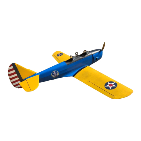
Dynaflite CHIPMUNK User manual

•BUILDS QUICKLY
•REALISTIC FUN SCALE® MODEL
•HUGE, 89" WINGSPAN (IMAA Legal)
READ THROUGH THISINSTRUCTION MANUAL FIRST.ITCONTAINS
IMPORTANTINSTRUCTIONSAND WARNINGS CONCERNINGTHEASSEMBLY
AND USEOFTHISMODEL.
Instruction Manual
WARRANTY
Dynaflite guarantees this kitto befreefromdefects inboth material and workmanship atthe
date of purchase. This warranty does not cover any component parts damaged byuse or
modification. Inno case shallDynaflite's liability exceed the originalcost of the purchased kit.
Further, Dynaflite reserves the right to change or modify this warranty without notice. Inthat
Dynaflite has no control over the finalassembly or material used forfinalassembly, no liability
shallbe assumed nor accepted forany damageresulting fromthe use bythe user of the final
user-assembled product. Bythe act of using the user-assembled product, the user accepts all
resulting liability. Ifthe buyer isnot prepared to accept the liability associated with the use of
this product, return thiskitimmediatelyinnewand unusedconditionto the place ofpurchase.
CHPGP03 PrintedinUSAV1.0Entire Contents © Copyright 2000

Introduction................................................2
Precautions
................................................2
Preparations
..............................................3
Required Accessories..........................................3
Optional
Accessories
..........................................4
Suggested
Supplies
............................................4
Building
Notes
....................................................5
Adhesives
............................................................5
Common Abbreviations......................................6
Types
of
Wood
....................................................6
Inch/Metric Ruler..................................................6
Die-Cut Patterns............................................7& 8
Buildthe Stabilizer
&
Elevators
................9
Buildthe Vertical Fin& Rudder................10
Buildthe
Fuselage
....................................12
Build
the
Bulkheads
..........................................12
Buildthe Wing
..........................................19
Join the Wing
Panels
................................23
Buildthe Ailerons
....................................26
Buildthe Flaps..........................................27
Mount
the Wing
to
the Fuselage
..............28
Finishthe
Fuselage
..................................29
FinalAssembly..........................................33
Finishing
..................................................35
Setthe ControlThrows
............................36
Balance
Your
Model
..................................36
Balance the Model Laterally
....................37
Preflight....................................................37
At
Home
............................................................37
At the Flying Site ..............................................38
Engine Safety Precautions
......................38
AMA
Safety Code (excerpt)
......................39
Flying........................................................39
Find
a
Safe
Place
to
Fly
....................................39
Takeoff................................................................40
Flight..................................................................40
Landing
..............................................................40
Congratulations on your choice ofthis kitfor
your next project.The Chipmunk isa FunScale®
model of a trueclassicaircraft.Ithas the
presence that only a big model can carry off.
At Dynaflite we take pride inoffering kits that
aresimple and straightforwardto build and
providevalueforyourmodelingdollar.
Because of the size and cost of this model we
assumeyou have builtseveralmodels and have
ageneralworking knowledge of modeling and
its terms. Ifyou HAVE NOTbuilt and flown
several kits, do yourselfa favor- back up and
get some experience before beginning this kit.
1.You must build the plane according to the
plan and instructions. Donot alter or modify
the model, as doing so may result inan unsafe
or unflyable model. Ina few cases the plan
and instructions may differ slightlyfrom
the photos. Inthose instances the plan
and written instructions are correct.
2.You musttake time to build straight, true
and strong.
3.You mustusea proper R/Cradio that isin
first class condition, the correct size of engine
and correct components (fuel tank, wheels,
etc.) throughout your building process.
4.You mustproperly installall R/C and other
componentsso that the model operates
properly on the ground and inthe air.
5.You must test the operation of the model
before every flight to insure that all equipment
isoperatingand you must make certainthatthe
model has remained structurallysound.
6.Ifyou are notalreadyan experienced R/C
pilot,you must fly the model onlywith the
helpofa competent,experienced R/Cpilot.
Remember: Take your time and follow
instructions to end upwith a well-built
modelthat isstraight andtrue.
2

Your Chipmunk isnot a toy,but a sophisticated
workingmodel thatfunctionsvery much like an
actualairplane.Becauseof its realistic
performance, ifyou do not assembleand
operateyour Chipmunk correctly, you could
possiblyinjureyourselfor spectatorsand
damage property.
Your Dynaflite Chipmunkisintended for
scale andgeneral sportflying includingmild
aerobatics suchas chandelles,stallturns,
loops androlls.Itsstructure isdesignedto
withstandsuchstresses. Ifyouintendto use
your Chipmunkfor more rigoroustypes of
flying such as aggressive aerobatics or
flying from rough fields, itisyour
responsibility to reinforce areas of the
modelthat willbesubjected to the resulting
unusuallyhighstresses.
Ifyou are callingfor replacement parts,
please look upthe part numbers and the
kitidentification number (stamped on the
end of the carton) and have them ready
when you call.
Tomake your R/Cmodelingexperience
totally enjoyable, get assistance with
assembly and your first flights from an
experienced, knowledgeable modeler.
You'll learnfasterand avoid riskingyour model
before you're truly ready to solo. Your local
hobby shop has information about flying clubs
in yourareawhosemembershipincludes
qualifiedinstructors.
You can also contact the Academy of Model
Aeronautics(AMA), which has more than2,500
charteredclubsacrossthecountry.We
recommend you jointhe AMA which will insure
youat AMA clubsitesandevents. AMA
Membership isrequired at chartered club fields
where qualified flight instructorsareavailable.
Contact the AMA at the address ortoll-free
phone number below.
Pleaseinspectallparts carefully before
you start to build!Ifanyparts are missing,
broken or defective, or ifyou have any
questions about buildingor flying this
model,please call usat (217) 398-8970.
You can also reach usbye-mail at:
productsupport@dyna flite. com
Academy of Model
Aeronautics
5151 East MemorialDrive
Muncie, IN47302
(800) 435-9262
Fax (765) 741-0057
Internet address:
http://www.modelaircraft.org
These arethe items "not included" with you kit,
thatyou willneed to purchase separately.Items
inparentheses such as (GPMQ4107) are suggested
part numbers recognized bydistributorsand
hobby shops and are listed foryourordering
Note:We, as the kitmanufacturer, provide
you with a qualitykitandgreat instructions,
butultimatelythe qualityandflyabilityof
your finishedmodeldepends onhowyou
assembledit;therefore, we cannotinany
way guarantee the performance ofyour
completedmodelandnorepresentationsare
expressed orimpliedastothe performanceor
Isafetyofyour completed model.
REQUIREDACCESSORIES
3

convenience. GPMisthe Great Planes® brand,
TOPisthe Top Flite® brand and HCAisthe
Hobbico® brand.
4-6 Channel Radio with One Standard Servo
(ThreewithFlaps)andFiveHighTorqueServos.
(2)"Y" Connectors (Ailerons, Flaps)
(2)12"Servo ExtensionWires
Engine - 1.08to 1.52-stroke, 1.2to 1.6
4-stroke or 25cc Gasoline
Exhaust Header, In-cowl Muffler
FuelFiller Valve (GPMQ4160 Glow,
GPMQ4161 Gas)
2-3/4" Spinner (GPMQ4527, Red)
Engine Mount and Mounting Hardware
16oz. Fuel Tank (GPMQ4107) (or Gasoline
CompatibleTank)
StandardFuel Tubing (GPMQ4131) (or
GasolineCompatibleTubing)
(2)4" Main Wheels (ROBQ1537)
(1) 1-1/2"Tail Wheel (GPMQ4243)
(4) 1/4"Wheel Collars(DUBQ1200)
(2) 1/8"Wheel Collars(GPMQ4304)
Top Flite MonoKote®Covering Film
(Approx. Four 6' Rolls)
Paint forFuelproofing and Painting the
Engine Cowl and the Canopy
(Dor(2)1/5Scale Pilot(s)
1/4"Latex Foam Rubber (HCAQ1000)
(19)Heavy DutyHinges (Twenty Seven
with flaps)(ROBQ2510)
AllPushrods and Control Hardware
-(5)4-40 Metal Solder Clevis (Seven with
Flaps) (GPMQ3814)
-(5)4-40 Hex Nuts (Seven with Flaps)
(GPMQ3304)
-(2) 4-40 x 12" Wire Pushrod,Threaded One
End (Four with Flaps) (GPMQ3752)
-(3)4-40x 48" Pushrods (GPMQ3718)
-(1) Throttle Pushrod (GPMQ3700)
-Throttle Hardware
4oz.Thin CAAdhesive - (GPMR6004)
4oz. Medium CA Adhesive - (GPMR6010)
2oz. Thick CA Adhesive - (GPMR6015)
CA Accelerator- (HCAR3750)
CAApplicatorTips- (HCAR3780)
6-Minute Epoxy - (GPMR6045)
30-Minute Epoxy - (GPMR6047)
4oz. AliphaticResin Glue (GPMR6161)
Great Planes Plan Protector (GPMR6167)
(2)Robart RoboStruts (Shock Absorbing)
(ROBQ1600)
SUGGESTEDSUPPLIES
OPTIONAL ACCESSORIES
-(4) Heavy Duty Control Horns (Six with
Flaps) (DUBQ1985)
-(5)4-40Threaded Metal Clevis (Sevenwith
Flaps) (GPMQ3794)
4

Aflat, durable, easy-to-handlesandingtoolis a
necessity forbuilding model airplanes.Great
.Planes makes a complete range ifEasy-Touch"
BarSandersandreplaceableEasy-Touch
adhesive-backedsandpaper.Onourworkbench,
we have four11"Easy-Touch Bar Sanders,
equipped with #50, #80, #150 and #220-grit
sandpaper. This setup isallthatisrequired for
almostanysandingtask.Customsandingblocks
can bemade frombalsa forsandinghard-to-
reach spots. We alsokeep some #320-grit wet-
or-dry sandpaper forfinishsanding before
covering.
Forfuture reference, here'sa listofEasy-Touch
BarSandersandadhesive-backedsandpaper:
5-1/2"BarSander(GPMR6169)
11"Bar Sander (GPMR6170)
22" Bar Sander (GPMR6172)
12'Roll of adhesive-backed sandpaper,
80-grit(GPMR6180)
150-grit(GPMR6183)
220-grit (GPMR6185)
Assortment pack of5-1/2"strips (GPMR6189)
BUILDINGNOTES
IMPORTANT:During construction you will be
using a number of balsasticks to framevarious
assemblies.Ample materialisincluded butyou
shouldstudy the plans, then make an effort to
cut the longest pieces you will need first. Label
the pieces as you cut them forlater reference.
By doing this now, you won't have to splice
piecestogetherlater.
ADHESIVES
This kitisbuiltwith three types of glue.
Cyanoacrylate:CAgluescure almostinstantaneously
andaremoderatelystrong.There aredifferent
viscositiesof CA'sintended fordifferent
conditions you will encounter when you build.
Thin CA isgreat for"tack-gluing," forglue joints
that fit well and forparts thatarealreadyjoined
butneed to bepermanently bonded. Medium
CA isused forgeneralconstruction where you
apply glue to one part, then joinitto another
part. Thick CA isgreat for glue jointsthat don't
fitperfectly or parts that requirea little time for
positioning beforethe gluecures.You will
encounter many other conditions that require
one or the other types of CA.
Always use CAina well ventilated area.Open
some windows or place a fanin the room to
circulate the air. Donot lean directly over your
work when you use CA and look away while it
cures or "sets off."CA can cure immediately
upon contact with skin so ifyou accidentally
bond your fingers, do not use vigorous motion
to separate them. Use CA Debonder (GPMR6039)
or acetone (nailpolish remover) or soak your
fingers inwarm water for a few minutes.
Never point the tipofa CAbottle toward your
faceand beespecially carefulwhen you unclog
aCAtip.Hobbico CAApplicatorTips(HCAR3780)
arehighly recommended and will help keep the
bottle fromclogging. Keep paper towels or
tissues closebyto immediately absorbexcess
CA dropped on your model or work area.Read
allthe warninglabelson your CA bottle. CA
Acceleratorisa chemical that you can spray
over uncured CA to make itcure immediately. A
mist spray of acceleratorwilldo the job.Donot
inhale the vapors! Some modelers "preprime"
5

the parts to be glued with accelerator, join
them, then add the CA. This way the CA is
guaranteedto cure immediately. This
prepriming isespecially handy when you use
thin CA because itwillcure before allof the
glue soaks into the wood away from the joint.
We do not recommend you build yourentire
model with this method and use accelerator
only when necessary. Often, oversprayfrom
acceleratorused hours or even days earlieron
nearby glue joints will cause the CA you use on
the next step to cure prematurelyand
unexpectedly - sobecareful!
Throughout the assembly of this model, THIN
CA shouldbe used unless the step calls for
another type of adhesive.
Aliphatic Resin: Resin glues requirethat parts
be pinned or clampedtogetherwhile the glue
dries; typically15- 30 minutes. Resin glues are
very strong and work well with balsa and
plywoods.
Epoxy: Epoxy glues arethe strongest but
require the most time to cure. Six-minute epoxy
cures the fastest; itsets within six minutes but
isnotfully cured for onehouror more.Thirty-
minute epoxy isthe strongest as itallows the
epoxy to soak into the wood thoroughly. While
itsets within 30 minutes, itisnotfullycured for
two or more hours.
COMMON
ABBREVIATIONS
Stab= HorizontalStabilizer
LE=Leadingedge(front)
TE=Trailing edge (rear)
Fuse= Fuselage
Ply= Plywood
"= Inches
TYPESOFWOOD
Balsa Basswood Plywood
InchScale
0"
1"
2"
3"
4"
5"
6"
0102030405060708090100110120130140150
MetricScale
6

Die-CutPattern
1REQ.
CHPGIPW06
1/16" X 3-3/8"X 16" PLY
CHPGW05
Note:Ifyouwillbebuildingfunctionalflapsforyour
Chipmunk, glue inthe lighteningholesinribsW4
and W5.
Note:This page shows the location of the die-cut
partsforthewing. Notall parts are marked on thedie
sheets. Besureto markallpartswith a ball point pen
prior to removing them from the die sheets.
2
REQ,
1/8" X 5-3/8"X 20-5/8"PLY
CHPGW042 REQ.
3/32"X 3"X 18" BALSA
CHPGW03A2 REQ.
3/32"X 3"X 30"BALSA
CHPGW032 REQ.
3/32"X 3" X 30"BALSA
CHPGW022 REQ.
3/32"X 3"X 30"BALSA
CHPGW012 REQ.
3/32"X 3"X 30"BALSA
7

Die-CutPattern
CHPGF051 REQ.
1/8"X 3" X 36"BALSA
CHPGF04
2
REQ.
1/8" X 3"X 36"BALSA
CHPGF031 REQ,
1/8" X 6-3/8"X 25-1/4"PLY
CHPGF021 REQ.
1/8" X 6-3/8"X 25-1/4"PLY
CHPGF012 REQ.
TOP DECK
FUSELAGE SIDE
CONTROL
HORN
MOUNTS
1/8"
X
6-3/8"
X
25-1/4"
PLY
Note:This page shows the locationof the
die-cut parts forthe fuselage.Not allparts are
markedon the die sheets. Be sureto mark all
parts with a ball point pen prior to removing
them from the die sheets.
8

1.Cut the stabilizerdrawing fromthe fuselage
plan and place iton your building board. Cover
the plan with Great Planes Plan Protector.
STAB SHEETING
1/16"X3"X30"
BALSA SHEETING USELEFTOVER
FORFINSHEETING
Q7. Sheet the stab with 1/16" x 3" x 30" balsa on
both the top andbottom. Dothiswith the stab
flaton your building board and use carenot to
twist itas you glue the sheeting into place. Use
pieces of leftover 1/16"balsa sheeting to sheet
the stab tips.
Q2.Cut the trailingedge from1/2" x 15/16" x
36" balsa and pin itinplace over the plan.
Ql3.Cut both leading edges from 1/2"x 15/16"
x36" balsa and pin them inplace over the plan.
Q4.Cut and fit the ribs from1/8"x 1/2"x 30"
balsa. Cut the longer ribs first.When satisfied
with the fit, glue them into position.
Ql8, Sand the trailingedge of the stab flatas
shown on the cross-sectionof the plan. Rough
sand the stab to the shape shown.
I—I9.Mark the centerline on the rear edge of the
TEalong its entire length.
l-l5.Cut and shape the tips from1/2" x 3/4" x
12" balsa using the plans as a guide. Glue and
pin them in place.
Note:Itisimportantthat the ribs fit the LEand
TEwell. Itisnot important that each rib fit the
exact location shown on the plan.
Q6.Remove the stab fromthe plan. Sand the
top and bottom surfaces flatand even. Use care
not to gouge any of the ribs.
LI10.Cut the fourstab fillerblocks from5/8" x
15/16" x 18"balsa and glue them to the center of
the stabTEas shown on the plan and photo.
Note that two of these blocks are cut to a width
of 3/4".
9

[.-111.Build both elevatorsatthe same time. Cut
the leading edges from5/8" x 1/2" x 30" balsa
and pin them to the plan.The leftover 5/8" x 1/2"
balsa will beused later for hinge blocks.
Ql12.Cutsome shims from 3/16"x 3/8"x 24"
balsa and place them in position over the plan
at theTE.The remainder ofthis stick willbe used
forthe fin ribs so besure to save at least 14".
l-t13.Cut the trailing edges from 1/4"x 3/4" x
30" balsa. Pin them into position on top of the
shims.
Q14.Cutand fit the eight elevator hinge blocks
from 5/8" x 1/2" x 30" balsa. Glue them into
position where shown on the plan.
Ql15. Cut and fitthe ribs from1/8" x 5/8" x 36"
balsa. Cut the longer ribs first. When satisfied
with the fit, glue them into position. Note that
the root and tip ribs extend fulllength. Note:It
isimportant that the ribs fit the LEandTEwell.
Itis
not
important that each rib fit the exact
location shown on the plan.
Q16.Notch the LEof both elevators where
shown on the plan and fit and glue the die-cut
1/8"ply horn bases into place.
Q17.Remove the elevators from the plan and
rough sand them to the shape shown inthe
cross-section. Use carenot to gouge the ribs.
Q18.Mark
the
centerline
of the
elevator
leading edges along their entire length. Using
the cross-section on the plan as a reference,
sand
theleading edges to the "V"shape
shown. Make sure the angle of the "V" is
enough to allowforthe full upand down
movement of the elevators.
Q1.Cover the fin/rudder drawing with Plan
Protector.
Q2.Glue the three die-cut 1/8"balsa fin leading
edge pieces together to form a LE lamination.
Pin this inplace over the plan.
[-I3.Cut the fin post (trailingedge) from 3/8" x
15/16"x 18"balsa and pin itinposition.
Q4.Cut the fin base from the remaining 3/8" x
15/16" balsa and pin itintoposition. Glue all
three pieces together.
10

5.Cut and fit the ribs fromthe remainder of
the 3/16" x 3/8" x 24" balsa. Cut the longer ribs
first. When satisfied with the fit, glue them into
position.
Note:Itisimportant that the ribs fit the LEand
TEwell. Itis
not
important that each rib fit the
exact location shown on the plan.
Q6.Remove the fin fromthe plan. Sand the top
and bottom surfacesflatand even. Use care not
to gouge any of the ribs.
FINSHEETING
LEFTOVER
STAB SHEETING
SCRAP
SHEETING
1/16"X 3" X 10-1/2"
BALSASHEETING
LJ7.Sheet the fin with 1/16" x 3" x 30" balsa on
both sides. Dothis with the fin flat on your
building board and use carenot to twist itas
you glue the sheeting into place.
Q8.Rough sand the fin to the shape shown in
the cross-section.
Q9.Cut the rudder leading edge from1/2" x
15/16" x 18"balsa and pin itto the plan.
Q10.Cut the rudder base fromthe rest of the
1/2"x 15/16"balsa. Glue and pin itinto place.
I—I11.The rudder tip leading edge isbuilt up
from three laminationsof die-cut 1/8"balsa
pieces, fora totalthickness of 3/8". Glue the
three pieces together and pin them inplaceon
the plan, using some leftover 1/16"balsa shims
where shown.
Q12.The rudder trailingedge isbuilt from two
laminationsof die-cut 1/8"balsa pieces, fora
total thicknessof 1/4".Build two of these
assemblies using theplan as a reference.
Q13.Cut some shims fromleftover 1/8" balsa
and place them inposition over the plan at the
TE where shown. Pin and glue the TE into
position.
Q14.Cut and fit the ribs from3/16" x 1/2"x 18"
balsa. Cut the longer ribs first.When satisfied
with the fit,glue them into position.
Note: Itis important thatthe ribs fit the LEand
TE well. Itis
not
important that each rib fit the
exact location shown on the plan.
Q15.Remove the rudder from the plan and
rough sand itto the shape shown inthe cross-
section.
Q16.Tack glue the rudder to the fin.
Q17.Sand the assembly to itsfinal shape.
Q18.Separatethe rudder fromthe fin. Sand
the trailingedge of the fin flatas shown on the
cross-section on the plan.
Q19.Mark the centerline of the fin trailing edge
and rudder leading edge along theirentire
length. Using the cross-section on the plan as a
reference, sand the rudder leading edge to
the "V" shape shown. Make sure the angleof
the "V" isenough to allowforthe full left and
right movement of therudder.
11

Q1.The fuselage plan isintwo pieces. Cutthe
planas indicatedandtapethetwo parts
together. Cut the fuselagetop view fromthe
plan. Cut the drawingsforbulkheadsB,C,D,F
andH fromtheplan.Placethe bulkhead
drawings on your workbench and cover them
with Plan Protector.
[-I3.Inner bulkheadD hasnotches cut in the
sides forthe longerons and longeron doublers.
These notches may be cut now or later when
the inner bulkhead isfitted to the fuselageside.
Q4.Place the fuselage side plan on your
workbench and cover itwith Plan Protector
frombulkhead D aft. Begin construction by
building the right rear side structure.
l-tQ 5.Using two 1/4"x 15/16" x 36" balsa sticks,
cut and fit the rear side longerons. Pinand glue
the parts into position.
Note:The top longeron ends at the leading
edge of the stab. A separate 1/4"x 15/16" x 5-9/16"
stab mount is glued to the rear of the top
longeron, 1/8"below the top edge. The bottom
longeronhas an angledcut and notch that fit
the top longeron and stab mount.
Q2. Build inner bulkheads B,C,D,F andH over
the drawings using 1/4"x 1/2"x 24"balsa sticks. Ql-l6.Cut the upright at bulkhead F from 1/4"
x1/2"x 24" balsa and glue itinto position.
12

[-]7.Locate oneofthe die-cut 1/8"ply forward
fuselagesides. Cut off the frontend of this side
along the embossed line.This willestablish two
degrees of right thrust. Note:Only the right
forwardfuselageside has this cut made.
I-J10.Place the right fuselageside over the plan
and mark the locations of bulkheads B,C,D,E,
F,G,H,HTW and I on the side. Placethe left side
over the right and transferthe marks to the left
side. Next, mark each inner bulkhead at the
center of the top edge. These marks and lines
will beused to align the fuselageinthe
following steps.
CUTALONG
EMBOSSEDLINE
RIGHTFUSESIDE
l-lQ 8.Fitthis ply fuselagefrontto the fuse rear.
Cut doublersforthe two jointsfrom1/8" x 1/4"
x30" balsa. When satisfied with the fit, glue the
ply frontand doublers to the fuse rear with
6-minute epoxy.
Q9.The left fuselageside is built over the right
side. Remove the right side fromyour building
board and turn itover. Use the leftover 1/8"x
1/4" stick to shim the forwardply side. Cover the
side with Plan Protector. Follow steps 5,6 and 8
to build the left side, aligningthe parts over the
right side. Donotcut the front end of the
leftforward plyside.
Q11.Glue inner bulkheads B,C and D to the
right fuselageside using 6-minute epoxy. Be
sure the bulkheads areat a 90° angleto the
side. Epoxy will produce the strongest jointbut
you can use thin CAwith acceleratorifyou are
ina hurry. Inspect each jointforgaps and re-glue
ifnecessary. Note:
The
top edge of each bulkhead
is1/8"below the top edge of the plyside.
13

Q12.Glue the die-cut 1/8"ply fuselagetop and
bottom decks to the right fuselageside. The
parts interlock. Donot glue the bulkheads to the
decks. IMPORTANT:Be absolutely certain that
the shorter side of the top and bottom decks are
glued to the right ply side. This establishes the
proper amount of right thrust. The frontof each
deck should extend exactly to the front of the
ply fuselageside.
t_] 15.Lightly sand the sides of bulkheads F and
Hto match the slope of the sides. Install them in
their proper locations inthe fuselagesides and
hold them inposition with pins.DoNOTglue
until later.
Q16.Place the fuselageupside-down over the
top fuselageplan. Alignthe top deck with the
plan and pin itinto place. Use some blocks to
hold the tailof the fuselageinplace over the
plan. Alignthe center mark on each bulkhead
with the centerline on the plan. Sight down
from above the fuselageto double check the
alignment.Whenyouaresatisfiedthat
everything isalignedproperly, glue bulkheads
F,H,and J to the fuselagesides.
Q17.Use the 1/4"x 1/4"x30"balsa stickto glue
across-bracebetween bulkhead D andF,and
between F and H.This bracing will make the tail
more rigid.
Q13.Glue the left fuselage side to inner bulkheads
B,C and D using 6-minute epoxy. Align the
bulkheads with the marks you made earlier.
Before the epoxy cures, sight acrossthe top of
bothsides to double check the alignment.
Q14.Pull the tailtogether andtack glue die-cut
1/8"ply bulkhead J to the rear of the longerons.
l-l18.Glue the die-cut 1/8" ply bottom bulkhead
formersAB and BB forbulkheads A and B into
position. Glue doubler BBD to the FRONT of BB.
Note:Make sure that AB followsthe angle
established forthe firewall.Use side formersA
and B to help incentering AB and BB.
14

Q19.Cut a stringer from 1/8"x 1/4"x 31"
basswood to length andglue into place to the
bottom offormersAB and BB.The remainder of
this stringer will be used on the top formers.
Ql20. Bend the forwardpart ofthe wing saddle
on the1/8" ply fuselageside alongthe
embossed cut line so that itconforms to BB.
Glue itinto position.
Q21.Gluethedie-cut1/8" balsabottom
bulkheadformersEB,FB,GB,HBandHTWinto
position.
l-l22.Tack glue the die-cut1/8"plybulkhead
former DB to the FRONT ofbulkhead D.Glue
another 1/8"x 1/4"x 31" basswood stringer to
the bottom of formersDB,EB,FB,GB, HB
and HTW.
Note: The exact position of DBwillbe
determined when the wing isfitted to the
fuselage.For now, just tack glueitso that the
stringer is straight.
Q23. Cut and fit the tailwheelmount blocks
from leftover 1/4"x 15/16"balsa using the
fuselage side view as a guide. These mount
blocks areglued to the bottom longeronat an
angleto conformto thecurve on bottom
formersHTW and JTW.Sand the blocks as
needed forthis angleand glue them to the
bottom longeron.
Q24.Glue the die-cut 1/8"ply tailwheelmount
into position on these blocks. Glue the die-cut
1/8" ply formerJTW to therearof this
assembly. Glue a piece of 1/8" x 1/4"basswood
stringer between JTW and J.
Q25. Remove the fuselageassembly fromthe
building board.
I-]26. Time to mount your engine. Before you
glue the firewallinto position, you should add
some reinforcing sticks to the inside of the
fuselageas shown inthe above photo. Use the
1/4"x 3/8" x 36" basswood stickforthis purpose
(DO NOTuse thelonger basswoodwing
spars).Glue them into position with 30-minute
epoxy. While you arewaitingforthe epoxy to
cure you can mount your engine to the engine
mount you have chosen. Position the mount on
the plan atthefirewallthen locatethe engine on
the mount to fit the frontof the cowl properly.
Check the position on the model to be sure
blind nuts and bolts will clearthe structure. If
15

you
will
be
using
the Great
Planes
Isolation
Mount™you will need to repositionthe
Mounting Grommets as shown on the plan.
Note:Depending on the type ofengine you are
installing,you may needto add spacers
between the engine mount and firewall. Layers
of
aircraftgrade1/4"plywood (not included)
work wellfor this. The firewall location is
designed so that a typical gasoline engine can
be
mounted on a GreatPlanes Isolation Mount
(GPMA2000, not included).
Gasoline Engine Note: Gasolineengines
mounted on an isolationmount, such as the
Great Planes Large Engine Isolation Mount™,
may need to bemounted on the centerline of
the model. This isneeded to obtain clearance
between the mounting bolts of the isolation
mount and the engine on the relatively narrow
firewall.Shim the engine as needed to obtain 0°
ofright thrust (about 1/8").
Most engines will fit inside the cowl ifthe engine
ismountedinverted.Besuretoallowforadequate
cooling.
Q27.Drill the 1/4"x 4-1/8"x 4-1/4"plyfirewall
as needed foryour engine mount and install
any required blind nuts. Glue the firewallto the
fuselagewith30-minuteepoxy.Foraddedsecurity
you can pin the firewall to the fuselage if
desired. Drill smallholes throughthe sides of
the fuselage into the firewalland epoxy insmall
dowelsor toothpicks.
Ul
28.
Once the epoxy has cured, install any
spacersneeded foryour engine mount. Besure
to install any blind nuts required to boltyour
engine mount to the spacers.
Q29. Glue the die-cut 1/8" ply and balsa side
bulkhead formersA, B,C,D,E,F,G and H into
position on both sides of the fuselage.The flat
end of A and B goes towardsthe bottom of the
fuselage.The flatend of the rest of the formers
goes towards the top of the fuselage(E and F
canbe glued on either way).The angled end of
Cgoes towards the bottom. Glue side former
DDto the rear ofD.Note that DDis slightly
wider than D and should protrude from D by
about 1/32".
Ql30. Cuttwo 3/16" x 3/16" x 24" balsa stringers
to length and glue them into place on side
formersDD,E,F,G and H.
Now isa good time to install the servos and
route the servo pushrods before any more
formersand sheeting are gluedintoplace.
There areeight die-cut 1/8"ply pushrod guides
provided forthis purpose. You may alsoneed
some leftover 1/4"x3/4" balsa sticks as well.The
plan shows theservos mounted justforwardof
theTEof the wing.This isa good location ifyou
will beusing a lighter engine such asa 1.20
4-stroke engine. Our prototype model, with an
O.S.FS-120Surpass 4-strokeengine,balanced
without any lead required with the servos
positioned as shown on the plan. Ifyou will be
using a heavier gasolineengine you may want
to mount the servos inthe tailof the model.This
can be done easily bynotching the longerons
for the servos, allowing them to protrude from
the fuselageside. Ifyou do this,usesome
leftover 1/4"x 3/8"basswood to reinforce the
longerons.
16

Note:Ifyou will beentering your Chipmunk in
IMAA events youneed to reviewtheir
requirements forservo and controllinkage
sizes.They requirehigh-torqueservoson
controlsurfacesand 4-40 size control linkages,
with metal clevises.
Q33, Glue the die-cut1/8" ply andbalsatop
bulkhead formersAT,BT,IP,(2) CT and (2)DT
into position.
Note:Make sure that AT followsthe angle
established forthe firewall.
Q31.Install the servos and route the pushrods
for the servo installation you will beusing.
Note:
You
will need to temporarily mount the
tailwheelassembly. The lower side longeron
willneed to be carvedout inthe areawhere the
pushrod clevis will connect to the rudder torque
rod horn.
Q34.Cut a 1/8"x 1/4"x 31"basswood stringer
to length andglue into place to top formersAT,
BTand IP.Dothe same forthe two CT top
formers.Use the remainder of the 1/8" x 1/4"x
31" stringer used on the bottom formers.
Q35. Glue the die-cut 1/8" piy and balsa top
bulkhead formersET,FT,GT,HTand I into
position.
Q32. Glue the 1/4" x 1-1/4" x 5-1/4" ply wing
hold down block into the slots inthe fuselage
sides with 30-minute epoxy. Cut and glue some
1/4" x 3/8" reinforcingsticks into place using a
leftover basswood stick.
Q36. Cut a 1/8"x 1/4"x 31" basswood stringer
to length and glue into place to top formersDT
(both),ET,FT,GTand HT.
17

1-137.Gluetwo sheets of 1/8"x 3" x 24" balsa
together to forma sheet 6" wide. Sand the outer
side of this sheet flatand smooth. Cut, fit and
glue this sheet into position to the left fuselage
side between side formersA and D with the
smooth side out. Alignthe top edge of the sheet
even with the top of the top deck. Note:This
sheet should extend only to former D and
shouldnotcover DD.Wet the sheeting as
needed to allow itto bend better.
Q40. Use some more leftover1/8" balsa
sheeting to cut, fit and glue fillerstrips between
the side sheeting and the ply fuselage sides at
the wing saddle area. Angle the strips slightly to
conform to the 6°dihedral angle of the wing.
Note:
There
isa small section of sheeting that
needs to beadded at bulkhead D.This will be
addedlaterwhen the fuselage bottom is
sheeted.
D38.Make and glue a second balsa sheetto
the right fuselageside.
Q39.Using some leftover 1/8"balsa sheeting
cut, fitandgluefillerstripsbetween the
sheeting you justadded and the fuselagetop
deck.You only need to do this inthe area of the
front andrear cockpits, between top formersIP
and CT and between CT and DT.
Q41.Use 1/8" x 3" x 30" balsa to sheet the top
of the fuselagebetween AT and IPAlso sheet
the area between the front and rear CT's.
LI42. Useleftover 1/8"x 3" balsa sheeting to
sheet the bottom of the fuselagebetween AB
and
BB.
Before the rear of the fuselage is sheeted the wing
must be fitted to the fuselage. So, it's time to:
18

QQ 1.Lay the right wing plan on your building
board and cover itwith Plan Protector.
Note:Itwill be easier ifyou prepare all four
leading edge wing skins at the same time.
BOTTOMWING SKIN
USELEFTOVER
FOROTHER SKIN
CUTFROM
CORNER
TOCORNER
3/32"
X 3"X
42"
BALSA SHEETING
CUT
LINE
3/32"
X 3" X 48"
BALSA SHEETING
SCRAP
BALSA
TOPWING SKIN
SAVE LEFTOVERFOR
FUSESHEETING
3/32"
X
3"
X
42"
BALSASHEETING
CUTLINE
SCRAP
BALSA
6-3/8"
WIDE
3"
WIDE
3/32"
X
3"
X
48"
BALSASHEETING
Q2. Prepare the four leadingedge wing skins
accordingto the sketches above. The skins for
the top of the wing are 3/8" wider thanthose for
the bottom. Glue the skins together using your
favoritemethod (we use masking tape to form
ahinge and then jointhem with aliphaticresin
glue).Sand the best side smooth with 150-grit
sandpaper.
UU 3.Pin the 1/4"x 3/8" x 44" basswood lower
spar over the plan.
l-lt-l4.Pin a 1/4"x3/8"x 44"basswood stick on
the dashed lines called"shim stick."This will
hold the rear of the ribs at the proper angleuntil
there areenough pieces to hold the wing rigid.
(Save the shim stick for later use.)
Q5.Punch the ribsfrom their die-cut sheets,
sanding the backs of the sheets lightly ifthey do
not come out easily. Number each rib as you do
so; don't forgetto number the aileronand flap
ribs as well. Check the fit of the spar to the spar
notches ineach rib.
Note:Ifyou will bebuilding functionalflapsfor
your Chipmunk, glue inthe rear lightening
holes inribs W4 and W5.
Q6.Glue the die-cut1/8" ply landinggear
doublerstoribsW2,W3andW4using 30-minute
epoxy. Glue them to the sides shown on the
6" WIDE
19

plan. There aretwo doublers forW2. The one
with the long cutout is glued to the side facing
the wing root. This cutout will lock inthe
landing gear stub (torque) block. Check the fit of
the landinggear block andstub block intheir
cutouts. Make sure you make a set forthe right
and left wing panels.
I-]Q 7.Glue ribsW2-W12into place on the lower
spar with a drop of CA, making sure they are
vertical. Pin the rear of each rib to the shim stick.
QQ 9.Glue the 1/4"x 3/8" x 44" basswood top
spar to the ribs.
QQ 10.Cut a 1/4"x 3/4" x 24" balsa stick to the
correct length and glue itto the rear ofW8-W12.
The tip end isglued to the side ofW12. Glue the
top flush with the top edges of the ribs.The stick
extends midway between W7 andW8.
QQ 11.Cut a 1/4"x 7/8" x 30" balsa stick to the
correct length and glue itto the rear ofW2-W8.
The root end isglued to the side ofW2.The tip
end glues to the side ofW8and the frontofthe
outerTE.
QQ 8.Usethe dihedralgauge to obtain the
proper angle (sixdegrees)ofW1. GlueWlinto
place on the lower spar. Pin the rear ofW1to
theshim stick. Use a long straightedgeto insure
thatWI isstraight.
QQ 12.Usethe remainder of the 1/4"x 7/8"
balsastick to cut and fit aTEpiece betweenW1
andW2.
20
Table of contents
Other Dynaflite Toy manuals

Dynaflite
Dynaflite Bird of Time User manual

Dynaflite
Dynaflite super decathlon User manual

Dynaflite
Dynaflite DYFA3030 User manual

Dynaflite
Dynaflite Daydream User manual

Dynaflite
Dynaflite Wanderer User manual

Dynaflite
Dynaflite Skeeter User manual

Dynaflite
Dynaflite Bird of Time User manual

Dynaflite
Dynaflite butterfly User manual

Dynaflite
Dynaflite PT-19 User manual

Dynaflite
Dynaflite Talon User manual
Popular Toy manuals by other brands

Mega Bloks
Mega Bloks Hello Kitty Celebration Series manual

Eduard
Eduard D9R Doobi w/armor slats - interior manual

Fisher-Price
Fisher-Price PORTABLE ENTERTAINER 79070 instructions

VTech Baby
VTech Baby Lights & Stripes Zebra Parents' guide

Eduard
Eduard ZOOM FE 1053 quick start guide

Eduard
Eduard 49 592 manual