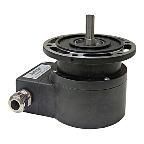
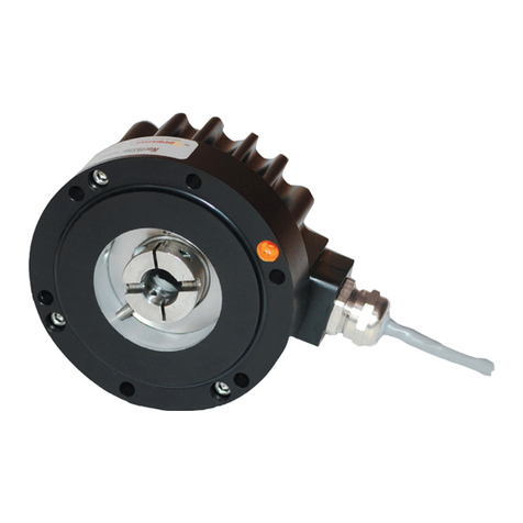
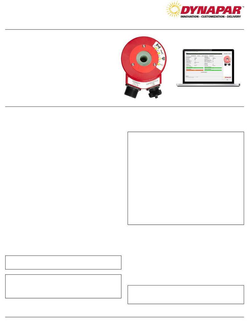
DYNAPAR NorthStar NexGen RIM Tach HT85 User manual

Encoder Installation Manual
ELECTRICAL CONNECTIONS
* Index (Z) optional. See Ordering Information
† Alarm not available with Pigtail cable. See Ordering Information
NorthStar™brand
NexGen RIM Tach HT85 Encoder
Key Features
SPECIFICATIONS
Common
B
A
Z*
Alarm †
Vcc (5-26 VDC)
B
A
Z*
Shield
1
2
3
4
5
6
7
8
9
10
Black
Green
Blue
Violet
N/A
Red
Yellow
Gray
Orange
Braid
Signal Connector Pin Pigtail Cable MS 3102E18-IT#
A
E
D
C
F
B
H
G
I
J
_
_
_
CONTENTS
Specifications ........................Pg 1
Important................................Pg 2
Mechanical Installation .........Pg 4
Sensor Module Installation...Pg 5
Electrical Installation.............Pg 6
Dimensions ............................Pg 7
Ordering Information.............Pg 7
• Hollowshaft Design Mounts Easily to Large Motor
Shafts, up to 4.50” in Diameter
• New Sensor Provides up to 0.075” of Air Gap,
Over 50% More Than Competitive Models
• Expanded Resolution up to 2400PPR
• Redesigned Circuitry for On-Board Diagnostics with
LED and Alarm Output
• Multiple Bore Sizes Available, Including Tapered Shafts
• Stainless Steel and Ductile Cast Iron Construction
EN 61326-1
STANDARD OPERATING CHARACTERISTICS
Code: Incremental, Magnetic
Pulses per Revolution: 60-2400 PPR
Phasing Sense: A leads B for Counter-Clockwise
rotation (CCW) viewing encoder-mounted end
Quadrature Phasing: 90° ± 45°
Symmetry: 50% ±15%
Number of Output Modules:
Single or Dual
ELECTRICAL
Input Power Requirements: 5-26VDC, 95mA
typical per sensor module, plus line driver load
Output Signals: IC-WE Differential Line Driver:
150mA, sink or source
Frequency Response: 0 - 180kHz Data & Index
Noise Immunity: Tested to EN61326-1
Electrical Immunity: Reverse polarity and short
circuit protected
MECHANICAL
Bore Diameter: 1” to 4-1/2”, straight or tapered
Mounting Configuration: Hollow Shaft mount
with Anti-Rotation Tether
Shaft Speed: 3,600 RPM
Shaft Length Required: 2.5” min
Acceleration Rate: 3,600 rpm/sec max
Allowable Shaft End-Play: 0.25” (Subject to
RPM Limitation)
Allowable Shaft Runout: 0.010” TIR (Subject to
RPM Limitation)
Housing Material: Cast Iron/Stainless Steel
Weight: 30 lbs
ELECTRICAL (Cont.)
Connector: 10 pin industrial duty latching, sealed
NEMA 4 &12, IP65. Optional MS3102 10 pin,
Pigtail Cable, or Latching connector on cable
extension
ENVIRONMENTAL
Operating Temperature Range: -40°C to +85°C
Storage Temperature Range: -40°C to +120°C
Shock (Sensor Module): 30 G’s Min
Vibration: 18 G’s @ 5-2000 Hz spectrum
Humidity: Up to 98% (non-condensing)
Page 1

Page 2
IMPORTANT INSTALLATION INFORMATION
FEATURES
All encoders have the following electrical features:
• Power (+DC)
• Common
• Output Signal(s)
Power (also referred to as supply, power source, and
power +V/VCC) is always +DC for encoders. There-
fore, power should always be connected to the
positive (+) side of DC power. In addition, encoder
power should be regulated to within ±5% at the en-
coder and should be free of induced transients. Com-
mon (also referred to as Com, supply common, and
ground) is generally a black wire (verify via Electrical
Connections table). Common should always be con-
nected to the negative (-) side of DC power.
All encoders have at least one output signal (A); how-
ever, it is common for encoders to have three signals
A, B, Z (may also be referred to as C, X, or index).
The outputs should each be connected to the receiv-
ing device at the appropriate terminal. NOTE: Never
connect A, B, or Z to the + or - side of DC power.
ELECTRICAL CONNECTIONS
Cable - The use of shielded cable is recommended
for all encoder installations. When a Dynapar brand
encoder is ordered, the type of termination is gener-
ally defined (usually the last selectable code in Order-
ing Information). If a code for a cable was indicated,
the encoder was manufactured to include a shielded
cable. If any other type of termination was selected or
if selection of termi-nation type was not requested, a
cable assembly must be ordered. (The cable assem-
bly easily hooks onto the encoder’s connector making
it ready for wiring).
To determine which cable assembly to order, refer
to the Electrical Connections table (in the encoder’s
manual).
GENERAL GUIDELINES
Encoders provide quality measurements and long
life when common sense, care, and accurate align-
ments are provided during installation. The following
general guide-lines will help to ensure a trouble-free
installation.
Mounting the Encoder
Wiring the Encoder
• Never connect or disconnect the encoder con-
nector or wiring while power is ON. Doing so may
damage the encoder.
• Power should always be connected to the + side
of DC power.
• Common should always be connected to the -
side of DC power.
• Never connect A, B, or Z to the + or - side of DC
power.
In some cases, there may be more than one table or
the table may be broken into sections due to different
output types. If so, refer to the information listed for
the output type selected for the encoder (in Ordering
Information).
Wiring should be run through dedicated conduits or
harnesses (not shared with any other wiring) which
are spaced at least 12 inches apart. This protects the
cable from physical damage while providing a degree
of electrical isolation. Also, do not run cable in close
proximity to other conductors which carry current to
heavy loads such as motors, motor starters, contac-
tors, or solenoids. Doing so could result in electrical
transients in the encoder cable which cause unde-
sired signal pulses.
NOTE: Never connect or disconnect the encoder
connector or wiring while power is ON. Doing so
may damage the encoder.
Grounding - DO NOT ground the encoder through
both the machine and the cable wiring. Connect the
shield at the input device only. NOTE: If the shield
is connected at both ends, grounding problems
that degrade system performance may result.
For European-based applications requiring CE com-
pliance, cable length must not exceed 30m. Connect
the shield to building ground on either the Encoder
or Controls end. CE compliant products are tested to
EN61326 EMC.
ELECTRICAL CONNECTIONS (cont.)
Do not shock the encoder. Do not subject the encoder to
axial or radial shaft stresses.
Do not tool the encoder
or its shaft.
Do not use makeshift techniques
to mount the encoder.
Do not use a rigid coupling.Do not disassemble the encoder.

Page 3
CONNECTIONS
Obviously not all receiving devices are the same.
However, connecting your encoder to one, no
matter what type or brand it may be, is not difficult. As
discussed in the previous section, all encoders have
certain electrical features. Each of these features/
functions are identified in the encoder’s Electrical
Connections table along with its corresponding pin
and wire color. Each wire specified in the table must
be connected to the receiving device.
Determining where to connect each wire is as easy as
following the Electrical Connections table and match-
ing each wire to the proper terminal on the receiving
device. In general, no matter what type of receiving
device you are using, the terminal strip is marked,
indicating the proper location for each function/wire.
These markings may either be numbers or text labels
identifying functions. If they are numbers, the receiv-
ing device’s manual should define what function
corresponds to each number.
Since receiving devices are made by various manu-
facturers, not all text labels/references are the same.
There are various ways to identify each function.
Following are a few examples:
LED STATUS LIGHT:
A multicolor LED Status light will indicate to the user
the overall condition of the encoder. The LED is built
into the encoder and does not require any additional
wiring or power to activate it. There are 4 basic status
conditions for the light:
1) LED off: No power to Encoder, Low supply voltage
(<3.0VDC), Total Failure of Encoder
2) LED Green: Correct Power to Encoder, Ready to
operate, No wheel movement Detected
3) LED Flashing: Unit operating, Unit sending pulses
out
4) LED Flashing Red: Low power to encoder
(<4.5VDC), Line Driver Failure, Line Driver Over-
Temperature (generally caused by external short
circuit), Line Driver Logic Failure
FREQUENTLY ASKED QUESTIONS
There are additional colored wires which are not
referred to in the Electrical Specifications table.
What do I do with them?
Do not connect them to the receiving device. Any
unused encoder signal wires must be individually
insulated and tied back. They should NEVER be
in contact with common, power sources, or other
output signal lines.
The encoder is correctly connected to the
receiving device per the Electrical Specifications
table and the receiving device’s terminal strip
label; however, it’s counting in the wrong
direction. What’s wrong?
In order to reverse the counting direction, the output
signal connections must be switched. If the encoder
has a single ended output, swap A and B. If the
encoder has a differential line driver, swap A and –
A.
I’ve connected the encoder and it doesn’t work (
No Outputs). What can I do?
Many encoders have internal protection circuits
which shut down the encoder to prevent damage
if the input power is not correct or the outputs are
overloaded. Check the following: Input Voltage (is
it too high?); Input Polarity (is it reversed?); and
Output Wiring (are they wired properly?).
I’ve read and followed the technical manual and
these guidelines and the encoder still doesn’t
work properly. Help!?
Calm down - help is at your fingertips! Simply pick
up the phone and dial our Applications Engineering
Department at 1-800-234-8731 (US & Canada) or
847-662-2666 from 8:00 AM to 4:45 PM (Central
time) Monday - Friday. One of our engineers will
gladly help you solve the problem.
Typical
Encoder
Power
Common
Signal A
Signal B
Index
Referred to as:
Vcc; + Power
DC Power
12VDC
Referred to as:
Comm
– Power
– DC
Referred to as:
Input A
A+
Sig. A
Referred to as:
Input B
B+
Sig. B
Referred to as:
Marker
Z
Sig. C
Note: Encoders that
feature differential
outputs will also have
complementary outputs
referenced as
A, B, Z (A-not, B-not,
Z-not).
_ _ _
FEATURES (cont.)
When encoders have a differential line driver, there
are two signals for each of the outputs. Each signal
(A, B and Z) has a compliment or inverse (A, B and Z
referred to as A not, B not, and Z not). The signal and
its compliment (i.e. A and A) are separate outputs.
Connect each output to a separate input.
NOTE: Never connect these signals together or to
the + or - side of DC power. Never connect
differential signals to the same input.
_ _ _
_
IMPORTANT INSTALLATION INFORMATION

Page 4
INSTALLATION
1.0 MECHANICAL INSTALLATION
The RIM Tach® HT85 is shipped partially assembled.
There are no field gap checks, axial alignment, or
run out checks required. Sensor Module shimming
may be required. The interchangeable stainless steel
sensor modules are available in a wide variety of
pulse counts. After unpacking the unit and verifying
receipt of the items listed on the packing list, proceed
with mechanical installation.
1. Place an anti-seizing agent such as a light moly-
grease or other high temperature, stable corrosion
inhibitor on motor shaft. This will aid not only
installation but future removal of the encoder for
maintenance, repairs, etc., and lessens chances for
corrosion.
2. Slide encoder housing onto motor shaft with flange
surface (back side-see Figure 2) facing the motor,
and tilted so the sensor head is facing downward. In
this orientation, the B channel will lead the A channel
when shaft rotation is CCW.
3. Remove black, trapezoidal access plate from the
encoder housing using an M4 (DIN 912) metric hex
wrench. Once removed, the clamping ring segment is
now available for tightening.
NOTE: Dual units require a hex wrench to remove
a module.
Figure 1: Encoder Housing Orientation
4. Tighten the clamping ring segment as follows (see
Figure 2):
1) Look inside the access plate hole and rotate
the hollow shaft until the two M5-0.8x12 mounting
screw heads on clamping ring are visible.
2) Being very careful not to damage the magnetic
pulse wheel (see Figure 2 below), tighten down
both mounting screws using the M4 T-Handle hex
wrench (included). Torque each mounting screw to
55 in-lbs (6.3 N-M regular) nominal, while ensuring
gaps on both radial ends of clamping ring segment
are approximately equal.
IMPORTANT: Be very careful not to touch the
pulse ring when tightening the cap screws.
The pulse ring is near the screws and can be
damaged easily. The magnetic properties of the
pulse wheel material can also be distorted or
erased by exposure to strong magnetic fields.
IMPORTANT: Do not unscrew the (2) cap screws
on the clamp ring completely, either when un-
installing or servicing the encoder. The screws
may fall inside the unit and would be difficult to
retrieve.
Figure 2: Clamping Ring Segment
5. Reinstall the access plate back onto encoder
housing, or place second sensor module assembly.
6. Attach/insert anti-rotation arm into the threaded
hole (3/8”-24 UNF) in the encoder housing (see
Figure 3). Complete approximately 10 turns of
the anti-rotation arm into stud. Tighten locking nut
(using a 9/16” open wrench) against the encoder
housing.

Page 5
Figure 3: Anti-Rotation Arm Orientation
7. Position anti-rotation arm at a 90° angle to the
motor shaft (perpendicular to motor axis and motor
C-face is recommended). This orientation ensures
three things:
• It provides enough clearance between the HT85
encoder and point of attachment (weldment angle or
channel bracket, motor face or foot, or other stable
mounting)
• It gives long moment arm from encoder centerline,
thus minimizing housing rotation and encoder error
caused by relative rotation
• It reduces misalignment of bearing rod ends which
prevents binding and premature wear due to high
degrees of angular misalignment
8. Loosely adjust anti-rotation arm to desired length.
Apply thread locker on threaded rod where bearing
rods will rest. The free end of the anti-rotation arm
should then be mounted to a stationary surface such
as a welded channel, angle, motor flange, or foot.
Tighten locking nuts (using a 9/16” open wrench)
against bearing rod ends and mounting stud.
IMPORTANT: Do not disrupt the anti-rotation
arm’s 90°alignment with the motor shaft during
mounting. A parallel orientation between
the anti-rotation arm and motor shaft is not
recommended because it will significantly
reduce the anti-rotation arm’s performance and
operational lifetime. Each rod end can withstand
only 50 of deviation. Ideally, the anti-rotation
arm should be mounted with rod-end ball
centered in its socket. Recommended torque: 20
ft-lbs. [27 N-m].
1.1 SENSOR MODULE INSTALLATION
To install the Sensor Module, perform the following
steps. See Figure 4.
1. Remove sensor module and mating connector
from packaging.
2. Separate mating connector from sensor module
by releasing the two latches.
3. Insert sensor module into opening in enclosure.
The sensor assembly is keyed to ensure proper
orientation.
4. Locate four M4-0.7 socket head screws. Insert the
screws through clearance holes in sensor module
and into tapped holes in enclosure. Tighten to a
nominal 15 in-lbs [1.7 N-m regular].
NOTE: There should not be a gap between the lip
on the housing and the enclosure. The stainless
steel sensor module is designed to seat in metal
to metal contact with the enclosure. Ensure that
no gaskets, paint, dirt, etc., interferes with the
complete seating of the module in the enclosure.
Figure 4: Sensor Module Installation

Page 6
1.2 ELECTRICAL INSTALLATION
IT IS VERY IMPORTANT that the mating connector
and the encoder body be isolated from electrical
ground in the wiring and conduit to prevent motor or
machine shaft eddy currents from going to ground
through the encoder bearings, as this will damage the
bearings over time. To insure that this is being done,
it is suggested that a plastic wiring/conduit adaptor or
non-conductive conduit is used to isolate the connector
from any metallic surface or conductive conduit. Please
see special note under table 1, for proper encoder
connector shielding. Also, to allow for proper encoder
grounding, the motor must be wired and grounded per
your local NEC Requirements.
Electrical connections are made to the sensor
module through a standard 1/2 inch NPT liquid tight
flexible conduit. The nipple length may be changed
to extend the outlet box if desired. Interconnection
cable recommendations are as follows: stranded
copper, 22 through 16 gage, braided or foil with drain
wire shielding 0.05 F maximum total mutual or direct
capacitance, outer sheath insulated. Shrink tubing may
be placed over any wires without insulation. For lengths
over 100 feet, use 18 gage or larger, to a maximum
of 1000 feet. If shielded twisted pair wire is used, do
not cross channels. Keep each pair of complementary
channel outputs together in a single twisted pair (e.g.,
A and A).
IMPORTANT: Reversing power and common will
not damage the unit. However, applying power to
any of the sensor outputs may cause damage.
Grounding: For applications with high ground
potential differences, DO NOT ground the encoder
through both machine and controls end. Connect
the shield at the controls end only. NOTE: If the
shield is connected at both ends, grounding
problems that degrade system performance can
result.
CE Grounding Measures – For best EMC
immunity the cable screen must be grounded on
both encoder and controls end. For cable lengths
longer than 30m or outdoor applications, additional
measures must be implemented to comply with
CE requirements. Connection of the encoder
to DC power supply network is prohibited if CE
compliance is required. CE-compliant products are
tested to EN61326-1 EMC.
In all cases, system CE compliance is ultimately the
responsibility of the manufacturer integrating the
encoder.
NOTE: The shield in the sensor module is
isolated from the frame of the encoder for
maximum noise immunity. The shield wire or
pin should be connected to the shield of the
cable and that of the drive or other receiving
device.
1.3 QUICK RELEASE CONNECTOR HOOD WIRING
To install the Quick Release Connector, perform the
following steps.
1.Remove the four screws from the mating connector
housing that hold the terminal block in place. Re-
move terminal block from housing.
2.Insert wiring through liquid tight flexible seal and
mating connector housing. Leave enough wire ex-
posed to comfortably reach the terminal block. Wire
to terminal block according to wire code in Table 1.
A similar wiring list is attached to enclosure.
3.Tighten Liquid Tight fitting on housing. OPTIONAL:
In some hostile environments, seal between con-
nector body and Sensor Module can be improved
by smearing a sealant (silicone grease, etc.) on the
neoprene seal of the connector.
4. Mate connector into place on sensor mount and
snap the two latches into place. If only one sensor is
being installed, ensure cover plate is installed over
other sensor hole.
Table 1. Signal Coding Table
* Index (Z) optional. See Ordering Information
† Alarm not available with Pigtail cable. See Ordering Information
Common
B
A
Z*
Alarm †
Vcc (5-26 VDC)
B
A
Z*
Shield
1
2
3
4
5
6
7
8
9
10
Black
Green
Blue
Violet
N/A
Red
Yellow
Gray
Orange
Braid
Signal Connector Pin Pigtail Cable MS 3102E18-IT#
A
E
D
C
F
B
H
G
I
J
_
_
_

Page 7
Code 5: Electrical
Code 3: Index
LNo Index
ZWith Index
Signal Output
Ordering Information
Code 2: PPR
Code 1: Model
HT8
HT8 Hollow
Shaft
Code 4: Wheel Bore
Thru-bores
T01 1-1/8”
T02 1-3/8”
T03 1-5/8”
T04 1-7/8”
T05 2.00”
T06 2-1/8”
T07 2-1/4”
T08 2-3/8”
T09 2-1/2”
T10 2-7/8”
Bores with 1.25” per
foot taper
P01 1-1/8”
P02 1-3/8”
P03 1-5/8”
P04 1-7/8”
P05 2.00”
P06 2-1/8”
P07 2-1/4”
P08 2-3/8”
P09 2-1/2”
P10 2-7/8”
Code 6: Termination
CLatching Industrial Connector
with 1/2” NPT
M10 pin MS Connector
P18” Pigtail
QLatching Industrial Connector
on 18” Cable
M25 25 mm
M40 40 mm
M48 48 mm
M55 55 mm
M65 65 mm
M70 70 mm
15-26VDC in,
5-26VDC Line Driver out
(IC-WE), Single output
25-26VDC in,
5-26VDC Line Driver out (IC-
WE), Dual output
1/2" NPT
CONDUIT CONNECTION
SECOND OUTPUT
(OPTIONAL)
ANTI-ROTATIONAL ARM
REFER TO ORDERING INFORMATION
FOR AVAILABLE BORE SIZES.
8X M4-0.7X20 SOCKET HEAD SCREW
TIGHTEN TO 15IN-LBF (REF)
.375X24 UNF
TIGHTEN TO 20FT-LBS (REF)
7.75±.25
[196.85±6.35]
7.96
[202.18]
15.92
[404.37]
12.31
[312.67]
0.87 [22.1]
2.13 [54.1]
0.1
[2.5]
2.81
[71.4]
8.71 [221.23]
DIMENSIONS inch
[mm]
Ordering Information
To order, complete the model number with code numbers from the table below:
European Sales Representitive
Hengstler GmbH (Germany)
Uhlandstrasse 49, 78554 Aldingen
www.hengstler.com
INNOVATION - CUSTOMIZATION - DELIVERY
Customer Service:
Tel.: +1.800.873.8731
Fax: +1.847.662.4150
Technical Support
Tel.: +1.800.234.8731
Fax: +1.847.662.4150
WWW.DYNAPAR.COM
Headquarters: 1675 Delany Road • Gurnee, IL 60031-1282 • USA NorthStar™ brand is a trademark of DYNAPAR. All rights reserved.
Document No. 703284-0001, Rev. A ©2020 DYNAPAR
Worldwide Brands: NorthStarTM • AcuroTM • DynaparTM • HengstlerTM • HaroweTM
For additional bore sizes up to 4.500” maximum, please consult the factory.
[13.31 [338] for bores above 2.875]
[17.92 [455] for bores above 2.875]
[8.96 [228] for bores above 2.875]
Note: See ACCESSORIES Section for Connectors and Spare Parts
Available with
bore sizes up to
2.875”
0060
0120
0240
0480
0960
1920
0064
0128
0256
0512
1024
2048
0075
0150
0300
0600
1200
2400
Available with
bore sizes up to
4.500”
Available with
bore sizes up to
3.875”
Table of contents
Other DYNAPAR Media Converter manuals

DYNAPAR
DYNAPAR HS20 Series Service manual

DYNAPAR
DYNAPAR NorthStar HSD44 Series User manual

DYNAPAR
DYNAPAR HS35IQ Series User manual

DYNAPAR
DYNAPAR NorthStar SLIM Tach ST56 User manual

DYNAPAR
DYNAPAR HS35iQ User manual

DYNAPAR
DYNAPAR NorthStar HD35R Series User manual

DYNAPAR
DYNAPAR NorthStar SLIM Tach SL56 User manual

DYNAPAR
DYNAPAR SERIES HS35R User manual

DYNAPAR
DYNAPAR SLIM Tach SL85 User manual

DYNAPAR
DYNAPAR M21 Series User manual