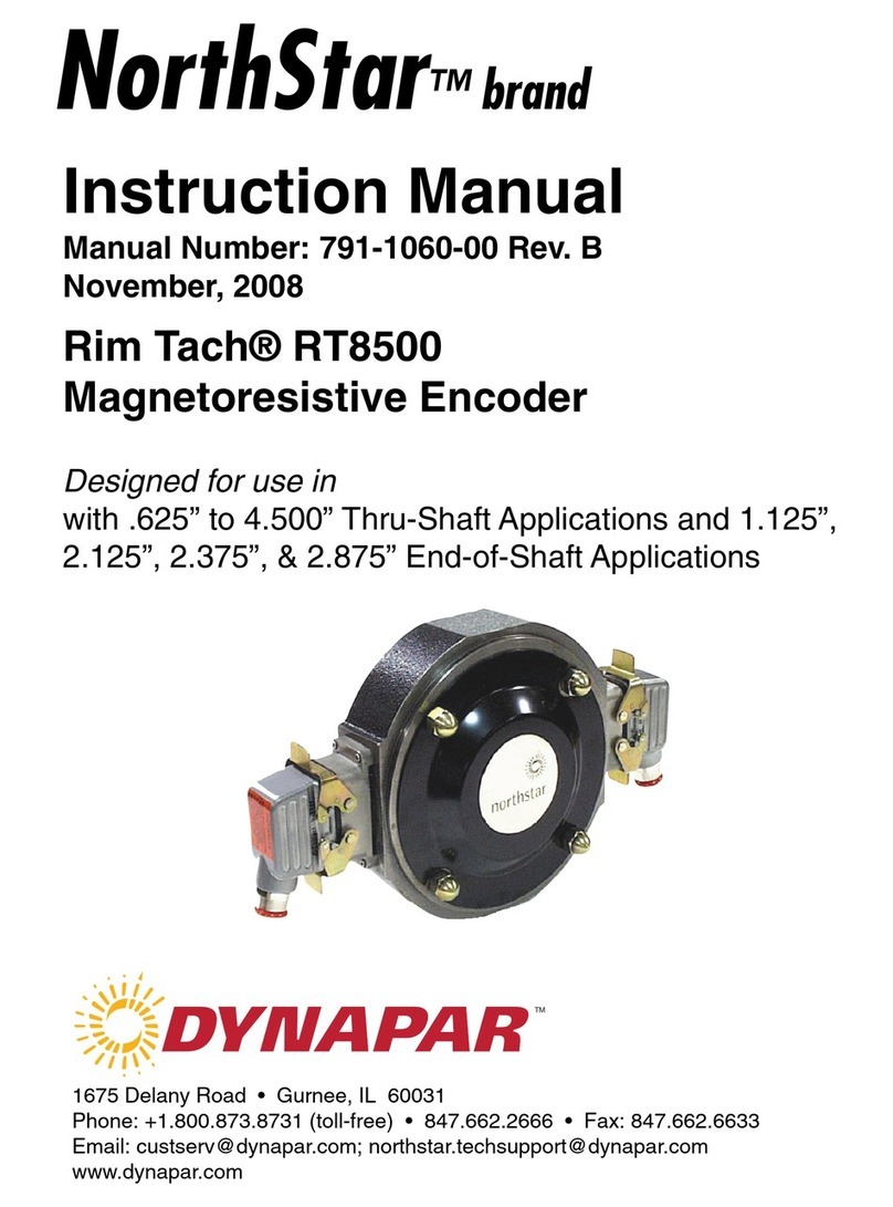
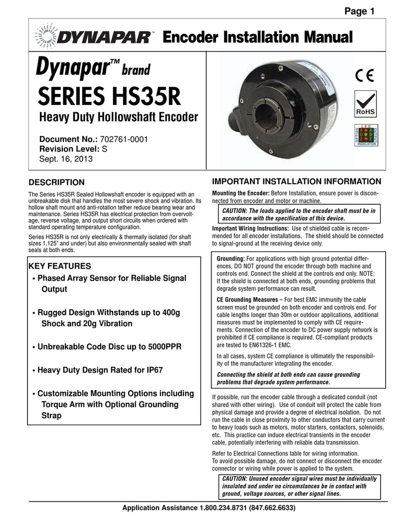
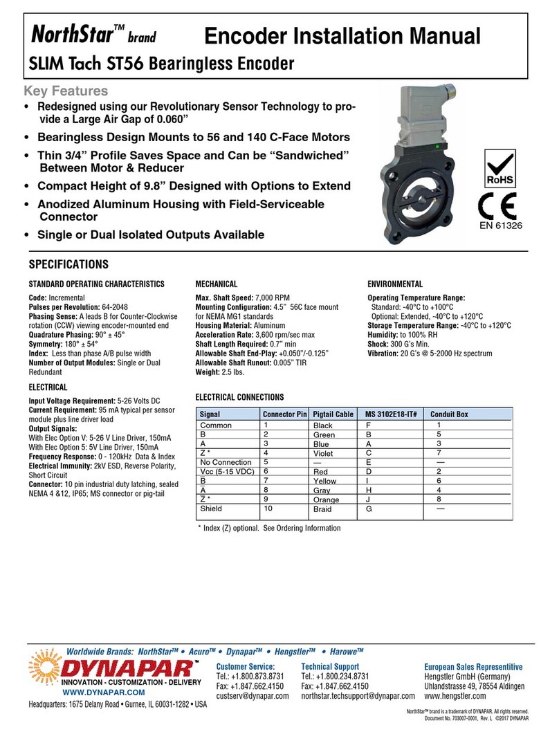
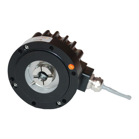
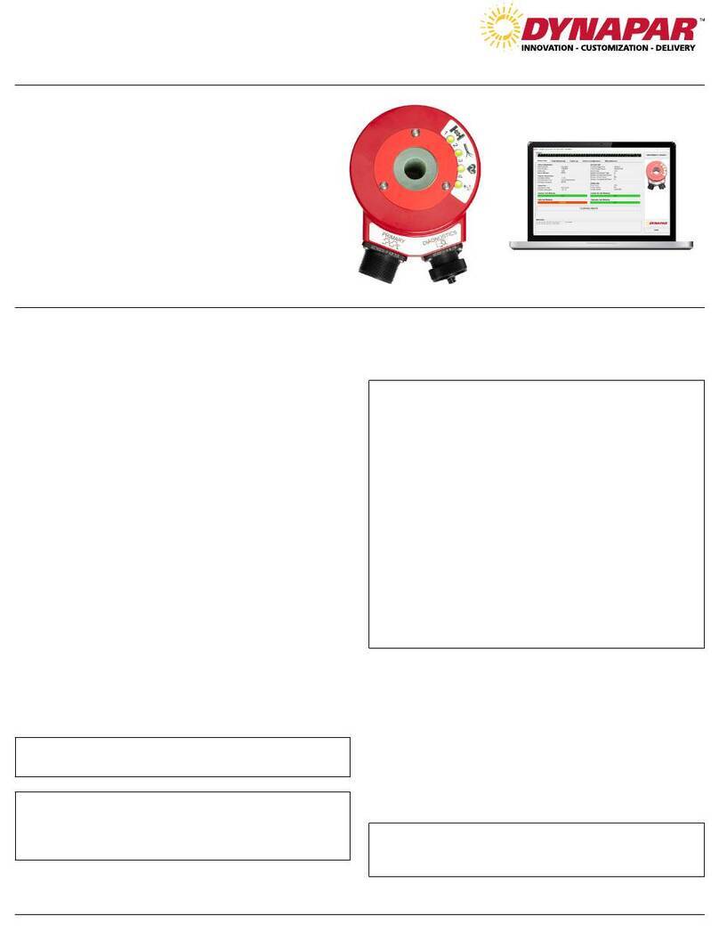
DYNAPAR NorthStar HD35R Series User manual

SERIES HD35R Heavy Duty Encoder
Key Features
•
Phased Array Sensor for Reliable Signal
Output
• RuggedDesignwithWide-Spaced
Oversized Bearings
• UnbreakableCodeDiscupto5000PPR
• ImprovedSealDesignforIncreased
MoistureResistance
European Sales Representitive
Hengstler GmbH (Germany)
Uhlandstrasse 49, 78554 Aldingen
www.hengstler.com
INNOVATION - CUSTOMIZATION - DELIVERY
Customer Service:
Tel.: +1.800.873.8731
Fax: +1.847.662.4150
Technical Support
Tel.: +1.800.234.8731
Fax: +1.847.662.4150
northstar.techsupport@dynapar.com
WWW.DYNAPAR.COM
Headquarters: 1675 Delany Road • Gurnee,,IL 60031-1282 • USA NorthStar™ brand is a trademark of DYNAPAR. All rights reserved.
Document No. 702854-0001, Rev. F ©2013 DYNAPAR
NorthStar™brand
EncoderInstallationManual
Worldwide Brands: NorthStarTM • AcuroTM • DynaparTM • HengstlerTM • HaroweTM
STANDARD OPERATING CHARACTERISTICS
Code: Incremental
Resolution: to 5000 PPR (pulses/revolution) See
Ordering Information
Format: Two channel quadrature (AB) with optional
Index (Z), and complementary outputs
Phase Sense: A leads B for CW shaft rotation view-
ing the shaft end of the encoder
Quadrature Phasing: For resolutions to
1200 PPR: 90° ± 15° electrical; For resolutions over
1250 PPR: 90° ± 30° electrical
Symmetry:
For resolutions to 1024PPR: 180° ±18° electrical
For resolutions over 1024PPR: 180° ±25° electrical
Waveforms: Squarewave with rise and fall
times less
than 1 microsecond into a load
capacitance of 1000 pf
ELECTRICAL
Input Power: 5-26VDC, 5-15VDC. 50 mA max.,
not including output loads.
Frequency Response: 125 kHz (data & index)
Termination: Pluggable screw terminals inside
terminal box with M20 cable gland exit
DATA AND INDEX
Not all complements shown
A shown for reference
(180°ELEC
Data A
Data A
Data B
Index
(90°ELEC)
A leads B, CCW (From Clamp End)
AleadsB,CW(fromshaftend)
WIRE COLORS
TERMINAL CONNECTIONS
Z
A
B
Z
B
A
COM
VCC
CASE
WIRE PRIMARY ALTERNATE
FUNCTION FUNCTION
Black paired w/ Green
VCC +UB
Green paired w/ Black
COM COM
Black paired w/ Blue
A K1
Blue paired w/ Black
–
A
–
K1
Black paired w/ Red
B K2
Red paired w/ Black
–
B
–
K2
Black paired w/ White
Z K0
White paired w/ Black
–
Z
–
K0
Shaft Material: Stainless Steel
Shaft Diameter: 11mm with 4mm key
Shaft Speed: 6000 RPM, Maximum
Starting torque: 12.0 in-oz. maximum (at 25°C)
Running torque: 5.0 in-oz. maximum (at ambient)
Bearings: Deep groove, Dual arrangement
Housing and cover: Hard Anodized Aluminum
Disc material: Mylar (unbreakable)
Weight: 4lb
ENVIRONMENTAL
Standard Operating Temperature: -40 to +85°C.
At shaft speed above 3000 RPM, derate 10°C per
1000 RPM
Extended Temperature Range: -40 to +100°C
(See ordering information)
Storage temperature: -40 to +100°C
Shock: 400g, 6mSec
Vibration: 5 to 3000 Hz, 20g
Humidity: 98%, non-condensing
Enclosure Rating: IP67; Custom Seal Option
available for environments with pressurized
carbon dust
MECHANICAL
SPECIFICATIONS

ApplicationAssistance1.800.234.8731(847.662.6633)
Page2
IMPORTANT INSTALLATION INFORMATION
FEATURES
All encoders have the following electrical features:
• Power (+DC)
• Common
• Output Signal(s)
Power (also referred to as supply, power source, and
power +V/VCC) is always +DC for encoders. There-
fore,powershouldalwaysbeconnectedtothe
positive(+)sideofDCpower. In addition, encoder
power should be regulated to within ±5% at the en-
coder and should be free of induced transients. Com-
mon (also referred to as Com, supply common, and
ground) is generally a black wire (verify via Electrical
Connections table). Common should always be con-
nected to the negative (-) side of DC power.
All encoders have at least one output signal (A); how-
ever, it is common for encoders to have three signals
A, B, Z (may also be referred to as C, X, or index).
The outputs should each be connected to the receiv-
ing device at the appropriate terminal. NOTE: Never
connect A, B, or Z to the + or - side of DC power.
ELECTRICALCONNECTIONS
Cable- The use of shielded cable is recommended
for all encoder installations. When a Dynapar brand
encoder is ordered, the type of termination is gener-
ally defined (usually the last selectable code in Order-
ing Information). If a code for a cable was indicated,
the encoder was manufactured to include a shielded
cable. If any other type of termination was selected or
if selection of termi-nation type was not requested, a
cable assembly must be ordered. (The cable assem-
bly easily hooks onto the encoder’s connector making
it ready for wiring).
To determine which cable assembly to order, refer
to the Electrical Connections table (in the encoder’s
manual).
GENERALGUIDELINES
Encoders provide quality measurements and long
life when common sense, care, and accurate align-
ments are provided during installation. The following
general guide-lines will help to ensure a trouble-free
installation.
MountingtheEncoder
Do not shock the encoder. Do not subject the encoder to
axial or radial shaft stresses.
Do not tool the encoder
or its shaft.
Do not use makeshift techniques
to mount the encoder.
Do not use a rigid coupling.Do not disassemble the encoder.
WiringtheEncoder
• Never connect or disconnect the encoder con-
nector or wiring while power is ON. Doing so may
damage the encoder.
• Power should always be connected to the + side
of DC power.
• Common should always be connected to the -
side of DC power.
• Never connect A, B, or Z to the + or - side of DC
power.
In some cases, there may be more than one table or
the table may be broken into sections due to different
output types. If so, refer to the information listed for
the output type selected for the encoder (in Ordering
Information).
Wiring should be run through dedicated conduits or
harnesses (not shared with any other wiring) which
are spaced at least 12 inches apart. This protects the
cable from physical damage while providing a degree
of electrical isolation. Also, do not run cable in close
proximity to other conductors which carry current to
heavy loads such as motors, motor starters, contac-
tors, or solenoids. Doing so could result in electrical
transients in the encoder cable which cause unde-
sired signal pulses.
NOTE:Neverconnectordisconnecttheencoder
connectororwiringwhilepowerisON.Doingso
maydamagetheencoder.
Grounding-DO NOT ground the encoder through
both the machine and the cable wiring. Connect the
shield at the input device only. NOTE:Iftheshield
isconnectedatbothends,groundingproblems
thatdegradesystemperformancemayresult.
For European-based applications requiring CE com-
pliance, cable length must not exceed 30m. Connect
the shield to building ground on either the Encoder
or Controls end. CE compliant products are tested to
EN61326 EMC.
ELECTRICALCONNECTIONS (cont.)
ApplicationAssistance1.800.234.8731(847.662.6633)
Page3
CONNECTIONS
Obviously not all receiving devices are the same.
However, connecting your encoder to one, no mat-
ter what type or brand it may be, is not difficult. As
discussed in the previous section, all encoders have
certain electrical features. Each of these features/
functions are identified in the encoder’s Electrical
Connections table along with its corresponding pin
and wire color. Each wire specified in the table must
be connected to the receiving device.
Determining where to connect each wire is as easy as
following the Electrical Connections table and match-
ing each wire to the proper terminal on the receiving
device. In general, no matter what type of receiving
device you are using, the terminal strip is marked,
indicating the proper location for each function/wire.
These markings may either be numbers or text labels
identifying functions. If they are numbers, the receiv-
ing device’s manual should define what function cor-
responds to each number.
Since receiving devices are made by various manu-
facturers, not all text labels/references are the same.
There are various ways to identify each function. Fol-
lowing are a few examples:
Typical
Encoder
Power
Common
Signal A
Signal B
Index
Referred to as:
Vcc; +Power
DC Power
12VDC
Referred to as:
Comm
–Power
– DC
Referred to as:
Input A
A+
Sig. A
Referred to as:
Input B
B+
Sig. B
Referred to as:
Marker
Z
Sig. C
Note: Encoders that
feature differential
outputs will also have
complementary outputs
referenced as
–
A, –
B, –Z, (A-not, B-not,
Z-not).
FEATURES(cont.)
When encoders have a differential line driver, there
are two signals for each of the outputs. Each signal (A,
B and Z) has a compliment or inverse (–
A, –
B and –Z
referred to as A not, B not, and Z not). The signal and
its compliment (i.e. A and –A) are separate outputs.
Connect each output to a separate input.
NOTE:Neverconnectthesesignalstogetherorto
the+or-sideofDCpower.Neverconnectdiffer-
entialsignalstothesameinput.
FREQUENTLYASKEDQUESTIONS
Thereareadditionalcoloredwireswhicharenot
referredtointheElectricalSpecificationstable.
WhatdoIdowiththem?
Do not connect them to the receiving device. Any
unused encoder signal wires must be individually
insulated and tied back. They should NEVER be
in contact with common, power sources, or other
output signal lines.
Theencoderiscorrectlyconnectedtothe
receivingdevicepertheElectricalSpecifications
tableandthereceivingdevice’sterminalstrip
label;however,it’scountinginthewrong
direction.What’swrong?
In order to reverse the counting direction, the output
signal connections must be switched. If the encoder
has a single ended output, swap A and B. If the
encoder has a differential line driver, swap A and –
A.
I’veconnectedtheencoderanditdoesn’twork(
NoOutputs).WhatcanIdo?
Many encoders have internal protection circuits
which shut down the encoder to prevent damage
if the input power is not correct or the outputs are
overloaded. Check the following: Input Voltage (is
it too high?); Input Polarity (is it reversed?); and
Output Wiring (are they wired properly?).
I’vereadandfollowedthetechnicalmanualand
theseguidelinesandtheencoderstilldoesn’t
workproperly.Help!?
Calm down - help is at your fingertips! Simply pick
up the phone and dial our Applications Engineering
Department at 1-800-234-8731 (US & Canada) or
847-662-2666 from 8:00 AM to 4:45 PM (Central
time) Monday - Friday. One of our engineers will
gladly help you solve the problem.
IMPORTANT INSTALLATION INFORMATION

ApplicationAssistance1.800.234.8731(847.662.6633)
Page4
MECHANICALINSTALLATION
1.InstallCoupling
If you are using Dynapar brand flex couplings,
please adhere to the max tightening specificatation
shown.
2.InstallFlange
Install encoder onto mounting flange or flange
adapter using four to six of the screw holes
provided on the encoder flange. Through a port in
the adapter, tighten the application end of the
coupling as shown.
3.InspectAssembly
Take care that all mounting dimensions and specifi-
cations meet the constraints shown below.
4.Connectorcoverinstallation.
a. Strip main cable jacket 2” from wire end.
b. Strip each wire used 0.1” from the wire end.
c. Feed the encoder cable through the strain relief.
d. Install each wire into the screw terminals of the
mating socket matching pin, color, and function,
respectfully.
e. Insert mating socket for the five pin and four pin
connectors onto the encoder pins.
f. Tighten screws on the sides of each connector to
secure the mating socket to the encoder pins.
g. Install main connector cover onto the encoder,
and tighten the two screws on opposite corners of
the cover.
h. Tighten the cable strain relief.
i. Verify that the strain relief is firmly clamped
around the complete 360˚ of the cable outer jacket.

ApplicationAssistance1.800.234.8731(847.662.6633)
Page5
DIMENSIONS inch
[mm]
Accessories: 114917-001, Isolated coupling, 11mm
6X 60°
1.70
[43,2]
4.85
[123,2]
.118
[3]
PILOT
1.42
[36]
Ø3.346
[84,99]
PILOT
Ø.434
[11,03]
3.00
[76,2]
3.30
[83,8]
Ø4.528
[115,01]
6X Ø.256
[6,5]
ON 3.937 B.C
[100]
MACHINED
SURFACE
4mm
KEY STOCK
2.26
[57,5]
2.73
[69,3]
.76
[19,3]
.85
[21,6]
OrderingInformation
To order, complete the model number with code numbers from the table below:
0 Terminal Box,
M20 gland
Blank None
01 Wind
Generator
Application
with Custom
Sealing
Ordering Information
Code 2: PPR Code 7: Options
Code 1: Model
HD35R
Heavy Duty
IEC Flange
Encoder
Code 3: Mounting
Code 5: Termination
HD35R
Code 4: Output Format
0001
0003
0010
0012
0015
0032
0050
0060
0100
0120
0200
0240
0250
0300
0360
0500
0512
0600
0900
1000
1024
1200
1500
2000
2048
2400
2500
3072
4000
4096
5000
0 Single Ended ABZ, 5-26VDC push-pull
1 Single Ended ABZ, 5-26VDC O/C
2 Single Ended ABZ, 5-26VDC O/C w2.2kOhm
H Same as “0” with Extended temp range
J Same as “1” with Extended temp range
K Same as “2” with Extended temp range
4 Differential AB only, 5-26VDC, 5-26VDC out *(7272)
5 Differential AB only, 5-26VDC in, 5VDC out *(7272)
A Differential AB only, 5-15VDC in, 5VDC out *(4469)
C
Differential AB only, 5-15VDC in, 5-15VDC out
*(4469)
L Same as “4” with Extended temp range
M Same as “5” with Extended temp range
6 Differential ABZ, 5-26VDC in, 5VDC out *(7272)
7 Differential ABZ, 5-26VDC in, 5-26VDC out *(7272)
8 Differential ABZ, 5-15VDC in, 5VDC out *(4469)
9 Differential ABZ, 5-15VDC in, 5-15VDC out *(4469)
N Same as “6” with Extended temp range
P Same as “7” with Extended temp range
W ABZ, 10-24VDC Line Driver for cable runs up to 500ft/120m
0100mm
IEC “Euro”
flange,
11mm
shaft w/
4mm key
Code 6: Housing
0 Anodized
Aluminum
* Line Driver Type

European Sales Representitive
Hengstler GmbH (Germany)
Uhlandstrasse 49, 78554 Aldingen
www.hengstler.com
INNOVATION - CUSTOMIZATION - DELIVERY
Customer Service:
Tel.: +1.800.873.8731
Fax: +1.847.662.4150
Technical Support
Tel.: +1.800.234.8731
Fax: +1.847.662.4150
northstar.techsupport@dynapar.com
WWW.DYNAPAR.COM
Headquarters: 1675 Delany Road • Gurnee,,IL 60031-1282 • USA
Worldwide Brands: NorthStarTM • AcuroTM • DynaparTM • HengstlerTM • HaroweTM
Table of contents
Other DYNAPAR Media Converter manuals

DYNAPAR
DYNAPAR NorthStar SLIM Tach ST56 User manual

DYNAPAR
DYNAPAR SERIES HS35R User manual

DYNAPAR
DYNAPAR NorthStar HSD44 Series User manual

DYNAPAR
DYNAPAR HS20 Series Service manual

DYNAPAR
DYNAPAR SLIM Tach SL85 User manual

DYNAPAR
DYNAPAR NorthStar NexGen RIM Tach HT85 User manual

DYNAPAR
DYNAPAR HS35iQ User manual

DYNAPAR
DYNAPAR HS35IQ Series User manual

DYNAPAR
DYNAPAR M21 Series User manual

DYNAPAR
DYNAPAR NorthStar SLIM Tach SL56 User manual