Servicio de Att. al Cliente
+34 986 288118
Servicio de Att. al Cliente
+34 986 288118
Application Assistance 1.800.234.8731 (847.662.2666) Page 1
Dynapar™brand
SERIES M21
Document No.: 702209-0001
Revision Level: J
October 24, 2016
Encoder Installation Manual
Modular Encoder
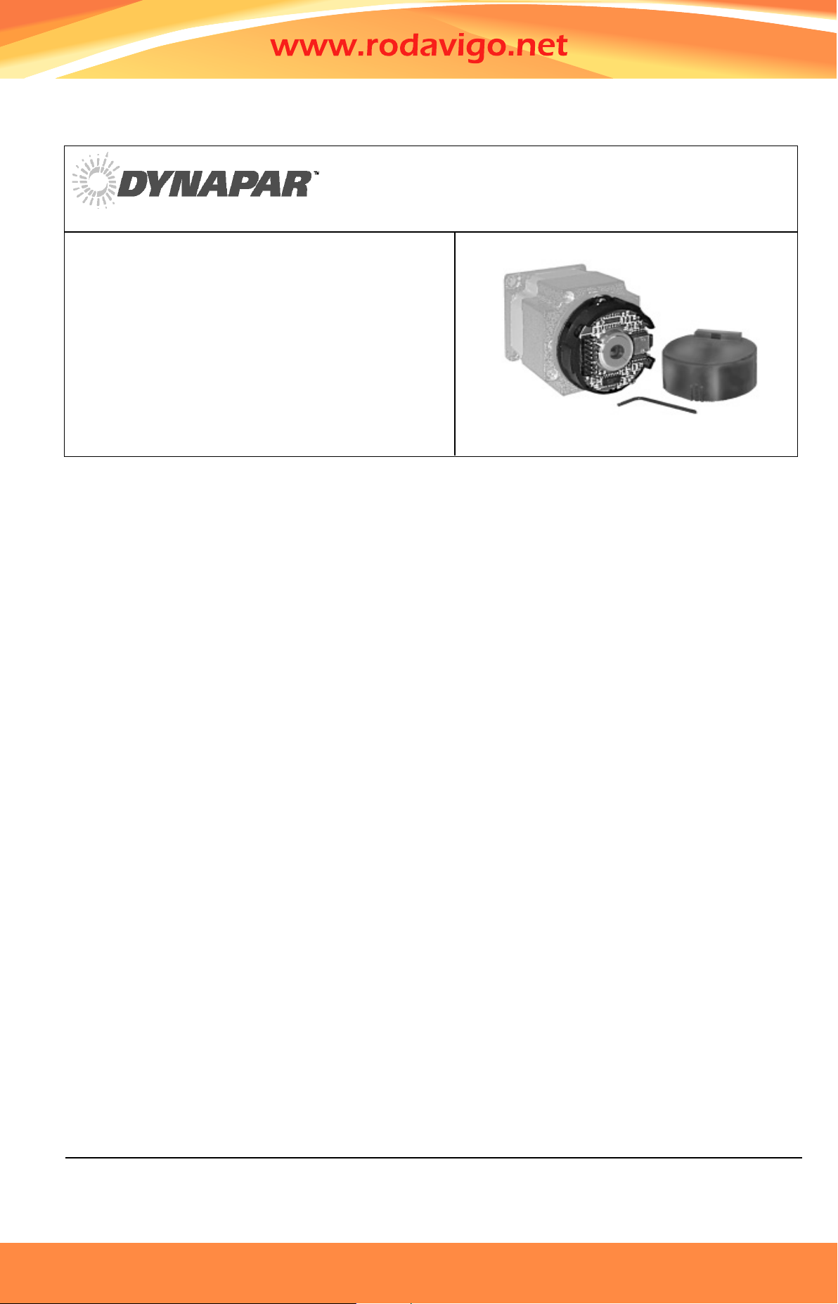
DESCRIPTION
The Dynapar brand M21 modular encoder
provides high-performance, cost effec-
tive feedback for stepper and servo motor
controls. Using industry standard package
dimensions, the M21 is easily installed
onto the motor without time-consuming
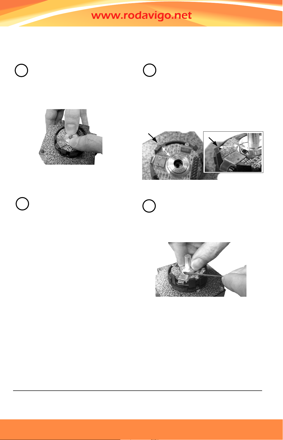
adjustments or special tools. Its unique
mechanical design automatically centers
and gaps the disc during installation.
For Brushless DC (BLDC) servo control,
optional 3 phase commutation tracks
replace the traditional Hall Effect sensors.
These optically-generated signals provide
higher accuracy and reliability, improving
the performance and reliability of the servo
system.
Dynapar Exclusive: The M21 design oper-
ates up to 120°C. The high temperature
plastics, phased array sensor, and low
current requirements stabilize the output
signals over a wide range of input voltage,
ambient temperature, or output frequen-
cies.
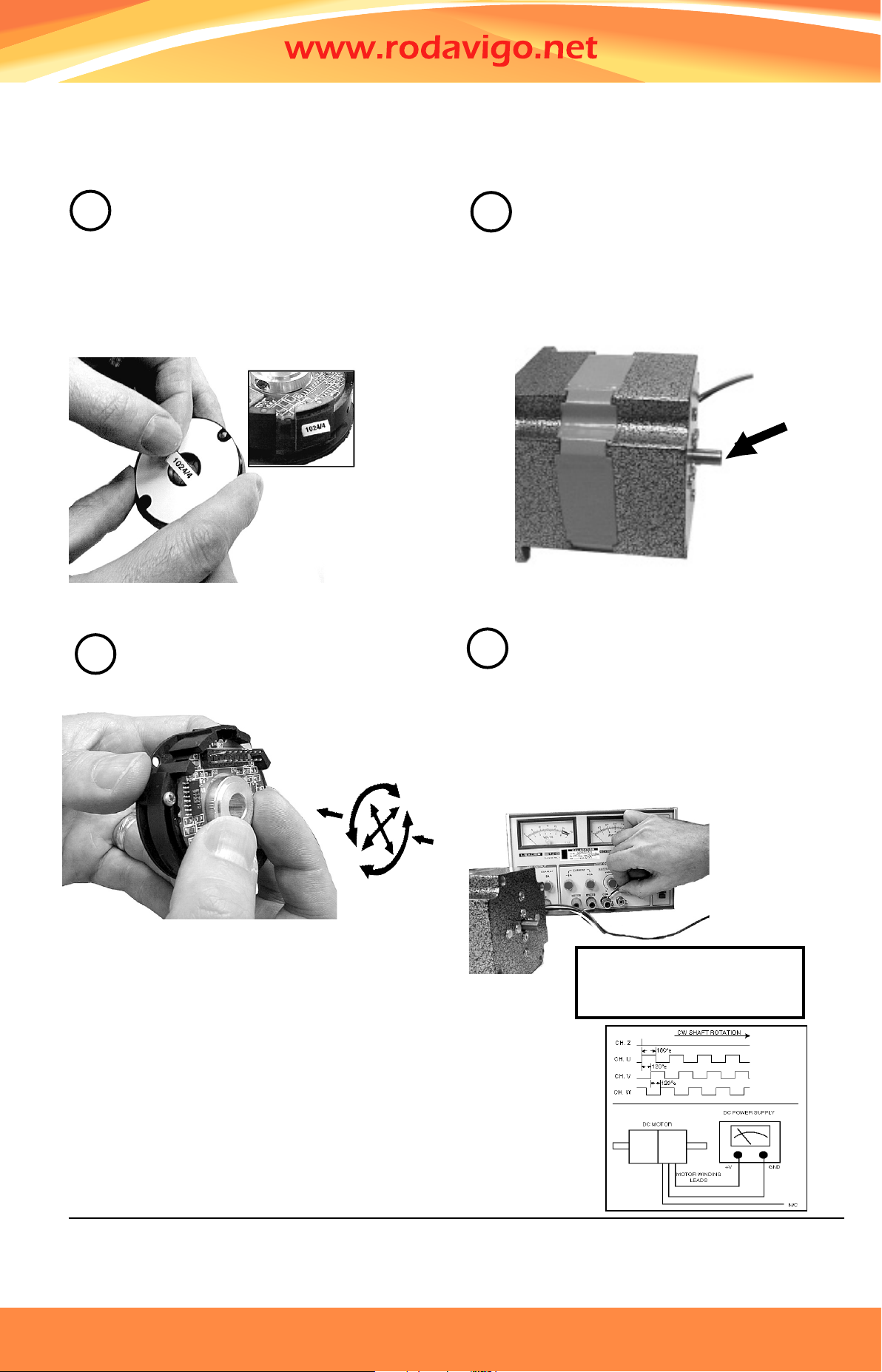
Dynapar Exclusive: The M21 provides 30
degrees of adjustment to align the signal
outputs to the shaft position. Using an
industry standard Size 21 modular mount-
ing pattern, the index mark on the disc hub
can be coarse aligned to the index sensor
position on the housing. The housing
rotates to allow further adjustment of the
index or fine alignment of the commutation
channels to the BLDC motor windings.
Dynapar Exclusive: The M21 enclosure is
dirt-tight, rated NEMA 1 / IP50. The cover
is gasketed to seal the disc and optics
from contamination. Additionally, the base
can be sealed to the motor for further
environmental protection.
Dynapar Exclusive: The M21 outputs are
protected from short circuits, and operate
on 5 or 12 VDC power.
SPECIFICATIONS MECHANICAL
Weight:
Connector: 1 oz. (28 gm) typ.
Connector w/cover: 1.5 oz. (43 gm) typ.
Cable: 2.5 oz (71 gm) typ.
Cable w/cover: 3 oz. (85 gm) typ.
Dimensions:
Outside Diameter: 2.1” (53 mm) max. with cover,
2.0” (51 mm) max. without cover; Height: 0.8”
(20.3 mm) max. (w/cover, excluding connector);
Emitter to Detector Gap: 0.070” (1.8 mm) min.
Material:
Base, Housing, & Cover: high temperature, glass
filled polymer;
Hub: Aluminum; Disk: 0.030” thick glass
Finish:
Base & Housing: black;
Cover: RAL 7010 (dark grey)
Moment of Inertia: 6.64 x 10⁻⁵ in-oz sec.2 (4.7 gm-cm2)
Hub Diameters: 1/4”, 3/8”, 7/16”, 1/2”, 6 mm, 8 mm,
10 mm, 12 mm nominal
Hub Dia. Tolerance: +0.001”/-0.000”
(+0.026 mm/-0.000 mm)
Mating Shaft Length: 0.45” (12 mm) min. blind hub
clamp screw, 0.65” (16.5 mm) exposed hub clamp
screw; 0.75” (19 mm) max. inside cover
Mating Shaft Runout: 0.002” (0.05 mm) max. (Includes
shaft perpendicularity to mounting surface)
Mating Shaft Endplay: +0.005”/-0.015” (+0.13 mm/-0.38
mm) nominal (“+” indicates away from mounting
face)
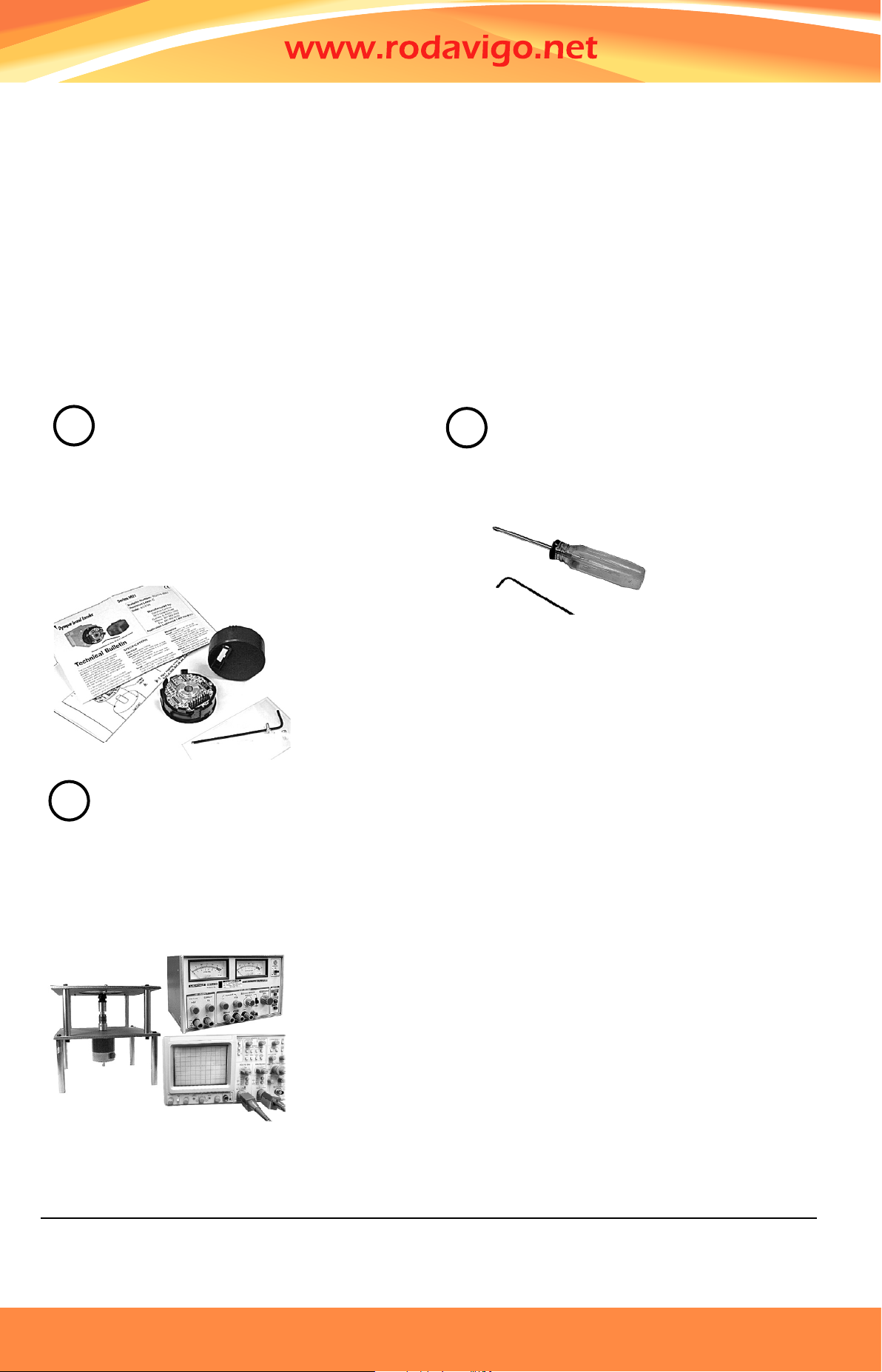
Mounting:
Base: (2) #4-40 (M2.5) #1 Phillips fillister head
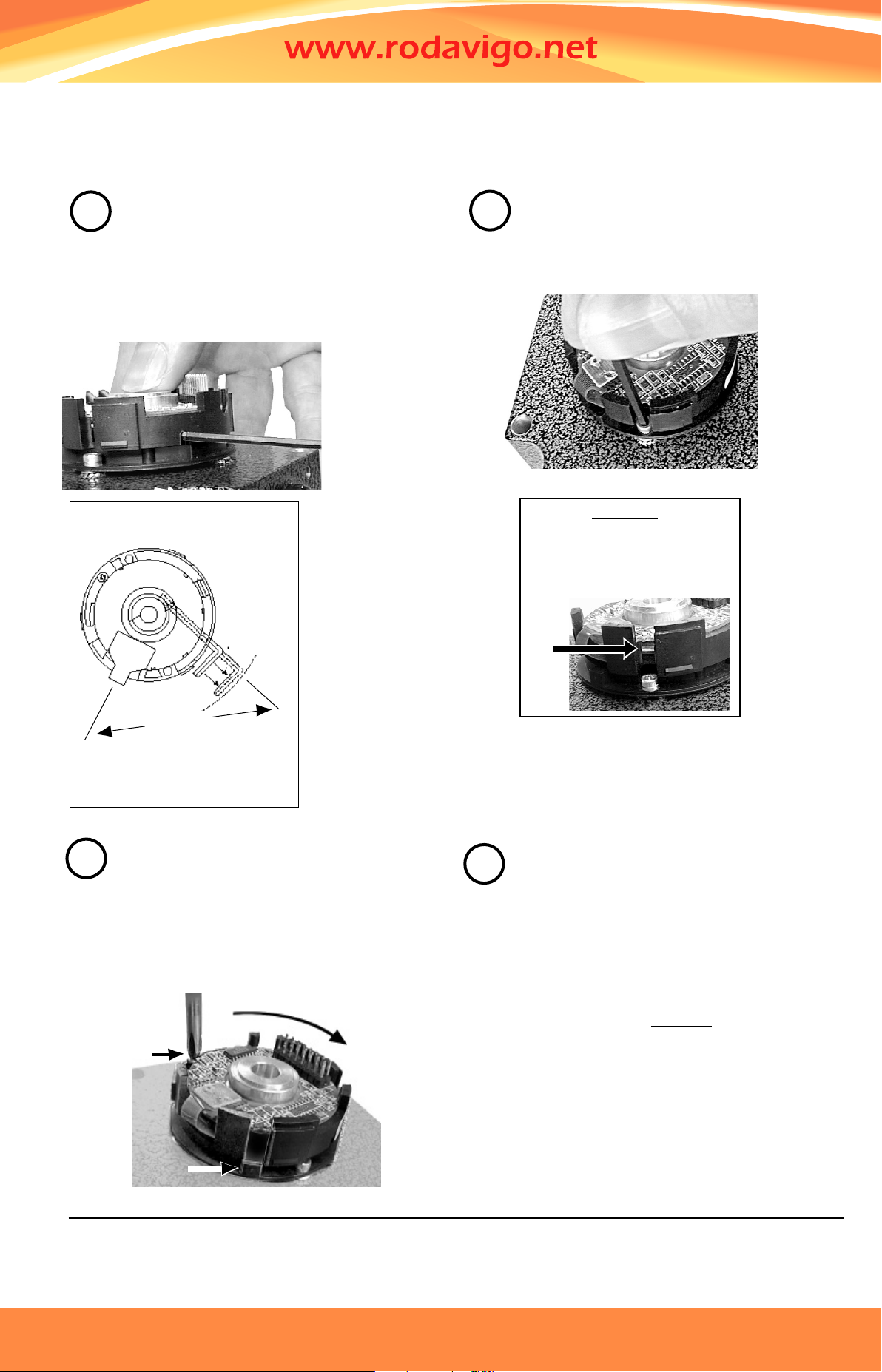
cap screw on 1.812” (46 mm) B.C., 0.01” (0.254
mm) true position to shaft; Shaft: split hub w/collar
clamp, #2-56 hex socket cap screw (5/64” hex
wrench included)
Electrical/Mechanical
Alignment Range: ±15° mechanical
Acceleration: 100,000 rad/sec.2max.
Velocity: 12,000 RPM max.
ENVIRONMENTAL
Operating Temperature: -40° to 120°C
Storage Temperature: -40° to 85°C
Shock: 50 G’s for 11 msec duration
Vibration: 2.5 G’s at 5 to 2000 Hz
Relative Humidity: 90% noncondensing
Enclosure Rating: NEMA 1 / IP50 dirt-tight (for models
with cover)
ELECTRICAL
Code: Incremental
Resolution: (pulses/revolution)
Incremental: 500 to 2048 PPR
Commutation: 2, 3, or 4 PPR
Accuracy:
Incremental: ±5 arc-mins. max. edge to edge;
Commutation: ±6 arc-mins. max.
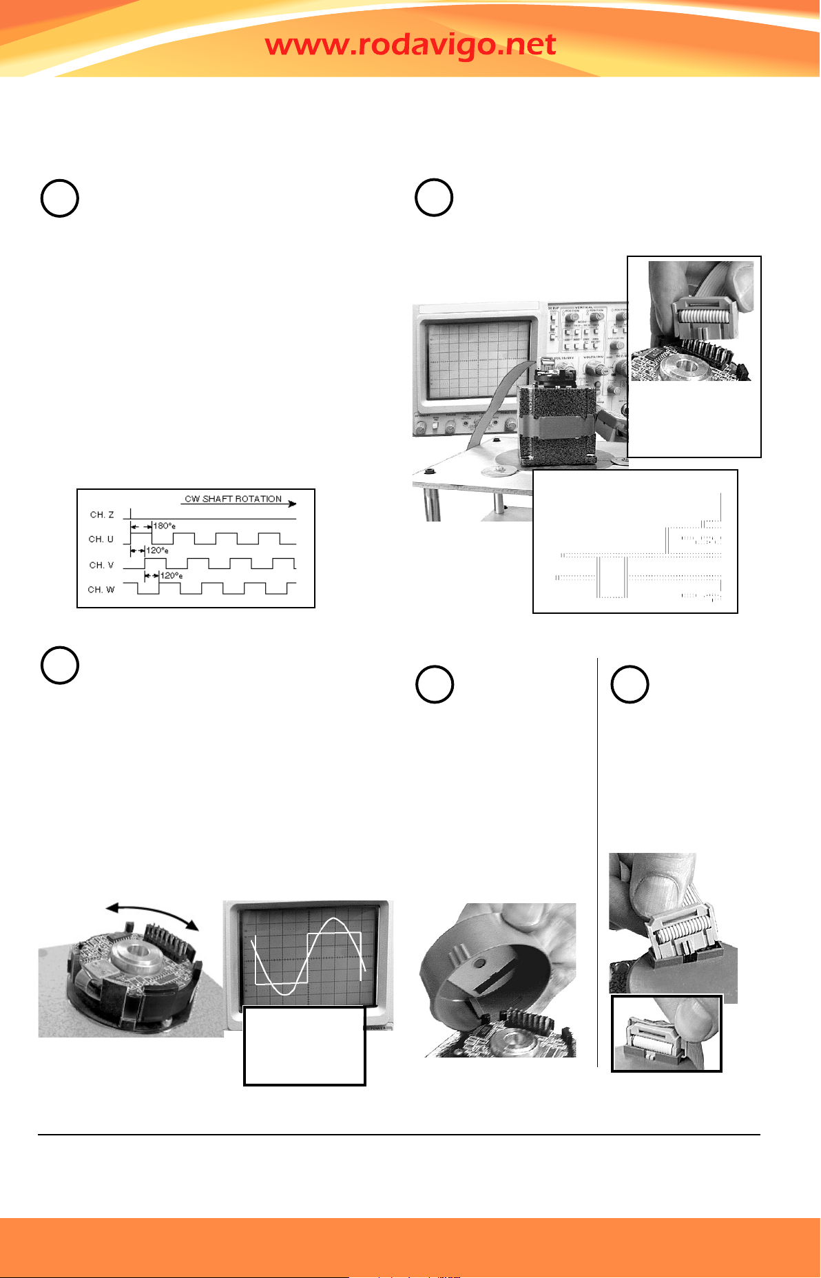
Sense: (viewing encoder mounting surface)
Incremental: A leads B by 90° for CCW rotation of
motor shaft;
Commutation: U leads V, V leads W by 120° for CW
rotation of motor shaft
Phasing:
Incremental: 90° ±18° electrical
Commutation: 8 Pole: 30°; 6 Pole: 40°;
4 Pole: 60° mechanical
Index to U Channel: ±1° mechanical - Index center
to U channel edge
Symmetry:
Incremental: 180° ±18° electrical
Commutation: 8 Pole: 45°;
6 Pole: 60°; 4 Pole: 90° mechanical
Index Pulse Width: 180° ±36° electrical (Gated with
B low) standard
Input Power Requirements:
Incremental: 5 or 12 VDC ±10% at 100 mA max.
(excluding output load);
Commutation: 5 or 12 VDC ±10% at 75 mA max.
(excluding output load)
Output Signals:
ET7272 Line Driver: 40 mA sink/source max.;
Open Collector w/2.0 kΩ pull-ups: 16 mA sink max.
Frequency Response: 200 kHz min.
Termination:
Connector: PCB mounted dual row head with 0.1”
x 0.1” pin spacing, 10 pins (incremental only),
16 pins (w/commutation); Cable: conductors - 28
AWG, stranded (7/36), insulation - black, PVC;
Shield: aluminum/polyester foil plus tinned, copper
drain wire (28 AWG, 7/36)
Noise Immunity: Conforms to EN50082-1 Light Industrial
for Electro-Static Discharge, Radio Frequency
Interference, Electrical Fast Transients, Conducted
Interference, and Magnetic Fields (for models or
applications with shielded cable)
Servicio de Att. al Cliente
+34 986 288118
Servicio de Att. al Cliente
+34 986 288118