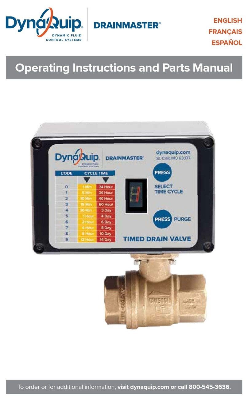
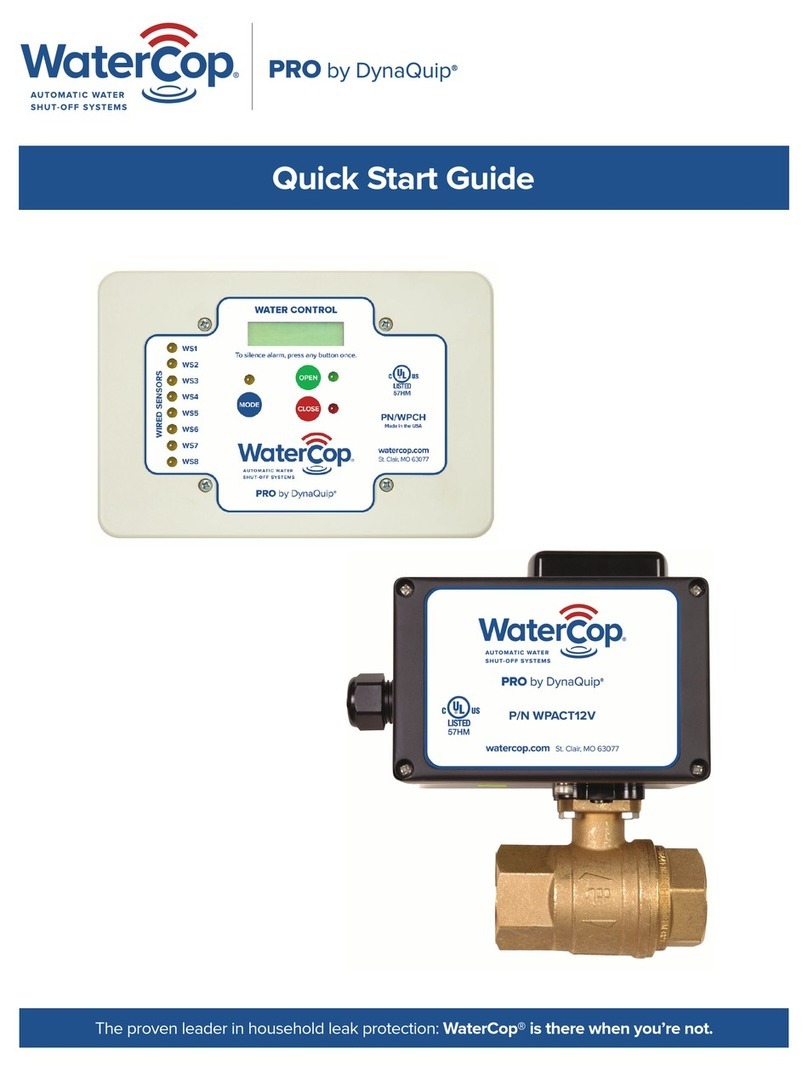
DynaQuip WaterCop LEAK STOP+ Programming manual

Owner’s Manual and Installation Guide
The proven leader in household leak protection: WaterCop® is there when you’re not.

2
Quick Start
1. Select installation location of valve, just upstream from inlet of water
appliance making sure the sensors can reach the ground
2. Using compression or solder fittings, install brass valve into inlet pipe
3. Mount Leak Stop+control box on valve (see page 4)
4. Apply power to Leak Stop+control box
5. Place sensors in areas where water would begin to accumulate
6. Test and restore to ready status
7. Please read entire manual and save for future maintenance reference
System Overview
WaterCop® Leak Stop+detects water leaks in your plumbing system at a
single location and automatically shuts o the water supply to that same
location. Early leak detection coupled with automatic water shut-o is the
best way to prevent extensive water damage.
Support and Assistance
Contact DynaQuip Controls for technical support and installation assistance:
Toll-free: 1-800-545-3636 (M-F, 8 AM-5 PM Central Time)
email: [email protected]
General Safety Information
WARNING:
•Do not apply electrical power to the unit unless the unit is fully assembled
(as it shipped). Failure to do so could result in personal injury and/or
damage to the unit.
•Disconnect power source before working on or servicing the unit. Failure
to do so could result in personal injury.
•Leak Stop+must be installed indoors. The ambient air temperature of
the Leak Stop+should be between 35˚ F and 105˚ F. Do not expose the
Leak Stop+to freezing temperatures or extreme heat.

3
•The valve closes with great force. It could cut o a finger. Keep fingers
and other items out of the valve when testing.
•The WaterCop® Leak Stop+case is NOT EXPLOSION PROOF. The shut-o
valve must NOT be installed where it could ignite flammable vapors or
explosive mixtures.
IMPORTANT:
•Adherence to all local and municipal building, plumbing, and electrical
codes as they pertain to the installation of the WaterCop® Leak Stop+
system is of utmost importance. Codes in some areas may require that a
licensed plumber be employed to do the installation, or that the proper
permits be obtained prior to any installation. Even if local codes do not
require a licensed plumber to do the installation, it is necessary that the
installer has a professional level of competence in both plumbing and
electrical skills to perform the installation. These instructions assume this
level of knowledge and skill. If in doubt, use a licensed professional.
•Check with original appliance manufacturer for instructions regarding the
special servicing of water heater (or other water bearing appliance) when
inlet water supply is stopped for any reason or length of time.
CAUTION:
It is strongly recommended that eye protection be worn while servicing the
system. Failure to do so could result in personal injury.
NOTICE:
WaterCop® Leak Stop+should be installed downstream of existing shut-o
valves and pressure reducers. Install 18" downstream from existing indoor
water meters to allow for future meter maintenance.
WARNING:
To reduce risk of electrical shock, fire, or damage to property or WaterCop®:
1. Use a common, 120 VAC outlet. Use of a surge protector is recommended.
2. Do not use extension cords
•Use of extension cords can cause fires or electric shock.
•Install WaterCop® Leak Stop+within reach of an existing outlet.
•Install an outlet near the Leak Stop+. Comply with all local codes.
3. Before opening case, unplug power cord. When the case is open, it is
possible to contact electrified components. Always unplug the power cord
before opening the unit.

4
System Components
WaterCop® Leak Stop+consists
of two components which may be
purchased together or individually.
1. The Leak Stop+brass valve
sized to the same diameter as
the existing supply line.
ANSI/NSF 372 approved full
flow, forged brass 400psi CWP.
2. The Leak Stop+electric
control box with attached
moisture sensors.
•12 VDC includes 120 VAC adapter
•2 (two) moisture sensors with 10'
(ten foot) cords.
Optional Parts and Accessories
Leak Stop+optional accessories and limited repair parts are available by
calling customer service at 800-545-3636.
SmartConnect
•24/7 control and access to your LeakStop + through the WaterCop app
•Mobile alerts about automatic closure and power outages
•Wi-Fi compatible
RS100 Wall Switch
•Convenient water shut-of from a wall mounted control panel
•Color coded LED valve position indicator lights
•Compatible with most automation/security systems and emergency
response auto dialers
Repair parts include:
•The complete Leak Stop+control box
•Replacement brass ball valve
•Sensor cord and probe (if damaged). The maximum number of sensors
the Leak Stop+is capable of supporting is 2 (two).
2
1

5
Installation Location
The WaterCop® Leak Stop+must be
installed indoors and directly into the
plumbing supply line, just upstream
of the appliance or area you wish
to monitor and protect. Leak Stop+
requires 120 VAC power to operate.
Verify location of an outlet within
easy reach of the Leak Stop+unit.
The attached moisture sensor will
be secured to the floor or catch pan
where water would first accumulate
if a leak occurs. The most common
area of installation would be a water
heater as illustrated here:
One Out
One In
7' Max

6
Installation Guidelines
Review all Safety Guidelines listed on page 3.
Use of a licensed, professional plumber is highly recommended and may be
required in some municipalities.
1. Separate the brass valve from the
control box by removing the spring clip.
RETAIN THIS CLIP.
2. Using compression fittings or sweat
fi tting adaptors, install the properly
sized brass valve into the plumbing
system, just upstream from the device
on the cold water supply. Orient the
valve in such a way that when the
Leak Stop+control box is properly
attached, the homeowner will have easy access to the open/close buttons.
Leak Stop+requires 120 V outlet to operate.
3. Verify that the valve and the Leak Stop motor are both in the OPEN position.
•The slot in the valve stem should be in line with the valve body, end to end.
The valve will be open.
•Apply power to the control box by plugging it into 120 VAC. The green
light should be ON. If not, press the green button and the unit will cycle
to the OPEN position. DISCONNECT POWER.
4. Mount the Leak Stop+motor onto the valve
and secure with the spring clip provided.
IMPORTANT: The control box MUST be
aligned with the valve as shown. Verify the
spring clip is firmly seated at all corners.
5. Plug in the unit to the selected nearby
120 V outlet.

7
Sensor Placement
Place the attached sensor probes in the areas where water would first accumulate
if a leak occurs.
Note: Care should be taken to place the sensor probe flat on the floor so water can
be detected as soon as it begins to accumulate. The gold pins should not come in
contact with any other objects or the flooring surface.
Sensors should be taped or adhered directly to the floor or pan under the monitored
appliance, however extreme care should be taken to avoid:
1. tape or adhesive touching or hindering
water reaching the gold pins;
2. the gold pins do not come into contact
with metal or other conductive services.
This may cause a false alarm of the system.
System Operation
The WaterCop® Leak Stop+constantly monitors the selected area for accumulating
moisture. When water comes in contact with the sensor probe, the Leak Stop+
control box will close the valve, shutting o the local water supply. The valve will
remain closed until it is manually reset using the green button on the Leak Stop+
control box. Lights on the Leak Stop+control box also indicate valve position
(Red = Closed, Green = Open).
The WaterCop® Leak Stop+valve may be controlled independent of a water leak
event using the open/close buttons on the front of the actuator.
The WaterCop® Leak Stop+requires an uninterrupted standard 120 VAC household
outlet. In the event of power failure, the Leak Stop +valve will remain in current
position. When power is restored, the valve remains in current position.
Sensor placed at a low spot
in the path of water flow where
it will make contact with sensor.
Probe
Water level

8
To silence the alarm, press one of the buttons on the face of the actuator.
After the leak is repaired, press the open button, the valve will open and the
system will return to normal.
12
VDC
12
VDC
JUMPER IS SET FOR DRY CONTACT
JP12
OUTPUT TERMINALS
ALARM OUTPUT SIGNAL
CONNECT TO COM1 AND NO1
JP
JUMPER IS SET FOR 12 VDC LIVE
ALARM OUTPUT SIGNAL
CONNECT TO GND AND COM2
OUTPUT TERMINALS
AUX DEVICE
YEL
+12 VDC
GND
GND
COM 1
COM 2
NO 1
NO 2
RED
BLK
BLU
GND
WATER PROBE
WATER PROBE
12 VDC
OUTPUT SIGNAL
MAX .25A (250mA)
+
AUX DEVICE
POWER SUPPLY
-
DRY CONTACT
OUTPUT SIGNAL
COM 1
N.O. 1
N.O. 2
+
-
12 VDC LIVE
Operating Instructions
Leak Stop+is capable of providing two alarm relay connections (dry contact
closures or 12 VDC signal) to report current valve position. When water is
detected by one of the sensors; the valve will close, the audible alarm will
sound, the indicator lights will display CLOSED, and the alarm relays will
activate. An auxiliary powered device, such as buzzer, lights, alarm, etc., can
be triggered from this output signal. See drawing below for wiring instructions.

9
Initial and Periodic Testing of the System
It is important that initial and periodic (monthly) testing of the system be
conducted to ensure continued protection against sudden and accidental
plumbing flooding.
Maintenance Procedure: Approx. _____ min./mo.
1. Verify that the Leak Stop +valve is plugged into a standard grounded
outlet and powered up.
2. Verify the Leak Stop +valve is in the OPEN position
(GREEN light illuminated).
3. Using a wet cloth, so as to not disturb adhesive (do not use distilled or
RO water), saturate sensor to activate valve closure.
4. The sensor will detect the water and the Leak Stop+valve will cycle to
the CLOSED position.
5. Verify the Leak Stop +valve is in the CLOSED position
(RED light illuminated).
•If Leak Stop+is installed on a water heater, you can additionally test
closure of the valve by then opening any downstream hot water faucet
in the home as if you were drawing hot water. As the residual water in the
pipe runs out, you will notice a slowing of flow and finally a stoppage of
water. YOU MUST TEST A HOT WATER FAUCET. Testing a cold water
faucet will not return an accurate result.
•If Leak Stop+is installed on any other water appliance, verify that outlet
flow has stopped by attempting to draw water from that device.
6. Remove the sensor from the water and dry thoroughly. Remember to close
any dry faucets you may have opened during testing.
7. Press the GREEN button on the Leak Stop+control panel to open the
valve and restore water supply.
8. Repeat steps 2 through 7 for the second sensor.
9. Test buttons.

10
Troubleshooting
Flood sensor does not detect water.
1. Verify the Leak Stop+is receiving power.
2. Verify the gold prongs are making continued and direct contact with water.
3. If testing, verify tap water is being used rather than distilled or RO water.
Leak Stop+RED or GREEN light does not illuminate
Verify the Leak Stop+is plugged into a grounded 120VAC household outlet and that
outlet is powered.
Leak Stop+motor does not close or open the valve correctly.
1. Verify the Leak Stop+is plugged into a grounded 120VAC household outlet and
that outlet is powered.
2. Verify the valve is correctly orientated to the control box. See page 6 (Installation
Guidelines No. 4).
3. If the brass valve has a solder connection, verify that the ball valve seats were not
damaged by excessive heat.
A. Remove the Leak Stop+control box (retain the spring clip for later re-attachment).
B. Using a flat-headed screwdriver, gently but firmly turn the ball valve stem open
and closed to move the ball. The flat-headed screw driver will fit into the slot
of the ball stem and you will be able to move the position of the valve manually.
C. Verify that the ball inside the ball valve can move. The ball will not be completely
loose, but you will be able to rotate it with slightly moderate pressure.
D. Return the ball stem back to the original position so that it will line up with the
drive of the actuator. The stem slot should be perpendicular to the length of the
valve and in-line with the pipe.
4. If the brass valve has a compression fitting connection, verify the compression fittings
were not over tightened causing damage to the valve, seal or seat.
A. Remove the Leak Stop+control box (retain the spring clip for later re-attachment).
B. Using a flat-headed screwdriver, gently but firmly turn the ball valve stem open
and closed to move the ball. The flat-headed screw driver will fit into the slot
of the ball stem and you will be able to move the position of the valve manually.
C. Verify that the ball inside the ball valve can move. The ball will not be completely
loose, but you will be able to rotate it with slightly moderate pressure.
D. Return the ball stem back to the original position so that it will line up with the
drive of the actuator. The stem slot should be perpendicular to the length of the
valve and in-line with the pipe.
5. If the valve does not complete the rotation due to blockage in the valve, the unit will
go into the ALARM state. Both lights will flash, alarm will sound and the alarm relay
will activate. To silence the alarm, press one of the buttons on the face of the actuator.
Refer to Troubleshooting section 4 for valve troubleshooting.

11
Limitations of the System
While this is an advanced design automatic water shut-o system, it does not oer
guaranteed protection against sudden or accidental discharge of water from a plumbing
system. Any automatic water shut-o system, whether commercial or residential, is
subject to compromise or failure to warn or activate for a variety of reasons. For example:
•Water intrusion from sources external to the plumbing supply system such as; rain,
hurricane, storm water, sewer back-up, swimming pools, spas, thawing snow and
ice, ice dams, HVAC condensation, freezer defrosting, etc.
•Water shut-o valves, water intrusion detectors and sensors, and many other sensing
devices will not work without power. Battery operated devices will not work without
batteries, with dead or insuciently charged batteries, or if the batteries are not
installed properly. Devices powered solely by AC power will not function properly if
their AC power supply is interrupted, however briefly, or cut o for any reason.
•Sudden and accidental water leaks from plumbing systems can occur at anytime
and at any point in the supply line system. Leaks that occur in areas not immediately
monitored by or in very close proximity to an active water leak sensor may not be
quickly detected or may not be detected at all by the leak detection system.
•This equipment, like other electrical devices, is subject to component failure. Even
though this equipment is tested at the factory prior to shipment and designed to
last as long as 10 years when properly maintained, the electronic components could
fail at any time.
•As with other electrical devices, power surges or spikes can cause circuitry to
malfunction or fail. Proper surge protection is necessary to avoid potential damage
to the electronics of this system.
•The automatic valve is designed to provide positive shut-o of the plumbing water
supply when connected to live AC power. However if the valve becomes corroded
or blocked due to normal sediment or other internal water line material build-up, the
valve may not function properly when needed.
The most common reason an automatic water shut-o system fails to perform when
needed is due to inadequate maintenance. DynaQuip Controls recommends this
system be tested monthly to make sure the automatic valve and both sensors are
working properly.
Installing an automatic water shut-o system may qualify a homeowner for lower
insurance premiums or a one-time credit. An automatic water shut-o system is not a
substitute for adequate insurance or proper home maintenance. Homeowners, property
owners, and renters should be proactive in protecting their property from sudden and
accidental water loss and continue to adequately insure their property against common
forms of damage.

Warranty and Exclusions
Limited Warranty: DynaQuip Controls Corporation, 10 Harris Industrial Park, Saint Clair, Missouri
63077, warrants its WaterCop® electric valve actuator and electronic sensor and electronic system
control components against defects in material and workmanship for a period of three (3) years
from the date of original shipment. DynaQuip Controls warrants its WaterCop® brass ball valve
mechanical component against defects in material and workmanship for five (5) years. In the event
that such defects appear within the warranty period, DynaQuip Controls will, at its option, and
upon written notification thereof and substantiation that, the product(s) have been stored, installed,
maintained and operated in accordance with DynaQuip’s recommendations and standard industry
practice, repair or replace the product without charge. All products repaired or replaced under this
warranty will be returned to purchaser ground freight prepaid by DynaQuip.
Exceptions to Warranty: This warranty shall be invalidated by any abuse, misuse, misapplication,
improper installation, modification, or disassembly at any place other than the point of original
manufacture. This shall constitute the exclusive remedy for breach of warranty, and DynaQuip
Controls shall not be responsible for any incidental or consequential damages, including, without
limitation, damages or other costs resulting from labor charges, delays, vandalism, negligence,
fouling caused by foreign material, damage from adverse water conditions, chemicals, weather, or
any other circumstances over which DynaQuip Controls has no control. Warranty will be voided if
the original serial number on the product is removed, whether by accident or intentionally. Product
purchased through auctions/online, auctions/overstock/liquidations etc. will not be covered by
the manufacturer’s warranty. If WaterCop® system components were not purchased directly
from DynaQuip Controls, please contact the vendors or retailers from whom such products were
purchased. DYNAQUIP CONTROLS MAKES NO OTHER WARRANTIES EXPRESS OR IMPLIED
EXCEPT AS PROVIDED BY THIS LIMITED WARRANTY.
The seller does not represent that the product; will prevent any property loss by sudden or
accidental discharge of water from plumbing systems into living area of a residential dwelling; may
not be compromised or circumvented; or that the product will in all cases provide adequate
warning or protection. Buyer understands that a properly installed and maintained automatic water
shut-o system may only reduce the risk of a sudden and accidental water loss event resulting in
significant water damage and is not insurance or a guarantee that such will not occur or that there
will be no personal injury or property loss as a result. CONSEQUENTLY, SELLER SHALL HAVE
NO LIABILITY FOR ANY PERSONAL INJURY, PROPERTY DAMAGE OR OTHER LOSS BASED ON
A CLAIM THE PRODUCT FAILED TO TURN OFF WATER SUPPLY OR GIVE WARNING OF A
POTENTIAL WATER LOSS EVENT. HOWEVER, IF SELLER IS HELD LIABLE, WHETHER DIRECTLY
OR INDIRECTLY, FOR ANY LOSS OR DAMAGE ARISING UNDER THIS LIMITED WARRANTY OR
OTHERWISE, REGARDLESS OF CAUSE OR ORIGIN, SELLER’S MAXIMUM LIABILITY SHALL NOT
IN ANY CASE EXCEED THE ORIGINAL PURCHASE PRICE OF THE PRODUCT, WHICH SHALL BE
THE COMPLETE AND EXCLUSIVE REMEDY AGAINST THE SELLER. This warranty gives you
specific legal rights, and you may also have other rights which may vary from state to state. No
increase or alteration, written or verbal, to this warranty is authorized.
DynaQuip Controls Corporation reserves the right to change or improve the design of any
DynaQuip Controls manufactured product without assuming any obligations to modify product
previously manufactured or sold.
192624 REV. B
To order or for additional information, visit watercop.com or call 800-545-3636.
Table of contents
Other DynaQuip Control Unit manuals
Popular Control Unit manuals by other brands

RabbitCore
RabbitCore RCM2200 Getting started manual

Metro DataVac
Metro DataVac Jamesbury 7000 Series Installation, maintenance & operating instructions

YASKAWA
YASKAWA VIPA SLIO FM 050 manual

Heritage Bathrooms
Heritage Bathrooms SDC04 Installation instructions and user guide

IVAR
IVAR MULTIMIX-C instruction manual

Grundfos
Grundfos CIM 500 instructions