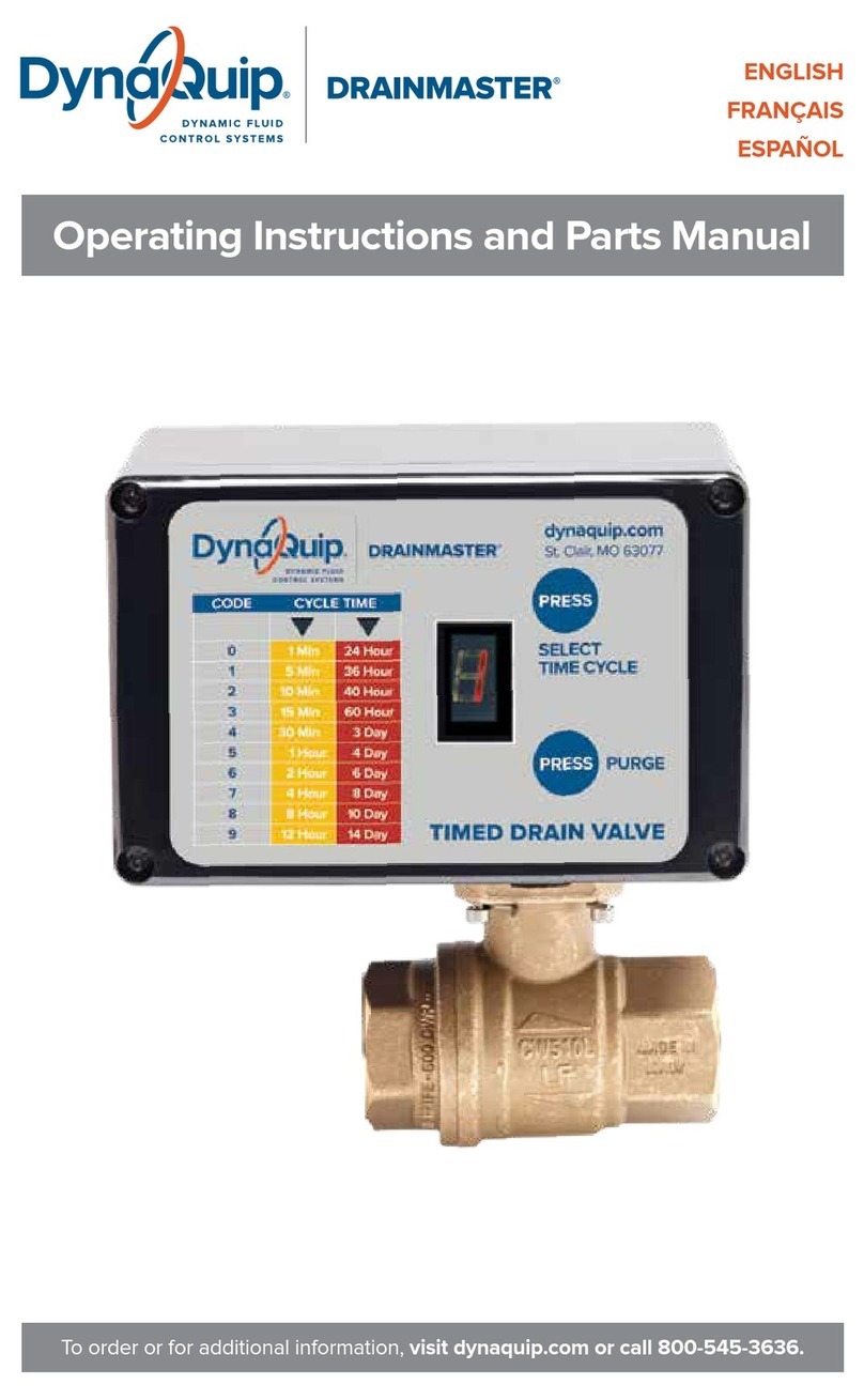
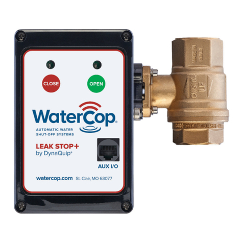
DynaQuip WaterCop Pro WPACT12V User manual

Quick Start Guide
The proven leader in household leak protection: WaterCop® is there when you’re not.

Before Installing the Valve
1. To mount the valve on the actuator, place the
O-ring on the valve in the circular indentation
around the stem.
2. Use a thin metal object that fits in the valve stem
groove to turn the valve and adjust it so that it is
aligned with the actuator.
3. Once the valve is aligned and in place, put the clip
on the four pins such that the curve is on the inside
of all four posts.
4. Make sure the Water Control Panel wiring matches
the wiring guide on page 3. To access the board,
remove the four screws on the front of the Water
Control Panel, remove the bottom and flip the front
panel so that the back is facing up.
5. Plug the Water Control Panel into a standard outlet.
KEEP FINGERS AND OTHER OBJECTS AWAY
FROM VALVE TO AVOID INJURY. You should hear
the actuator turn the valve one full cycle.
6. Test the actuator by removing the rubber stops at
both ends of the valve and checking to see the
valve position. The indicator lights on the Water
Control Panel should show the correct current
position of the valve.
7. Change valve position by pressing the UNLIT “OPEN”
or “CLOSE” button. Press the UNLIT indicator, either
“OPEN” or “CLOSE”, whichever one does not have
a LIT light next to it to tell the actuator to perform
one-half cycle.
KEEP FINGERS AND OTHER OBJECTS
AWAY FROM VALVE TO AVOID INJURY.
8. Visually verify that the valve has changed position.
9. Repeat steps 10-11 a few times by pressing the
alternating UNLIT button “OPEN” or “CLOSE” to
test and exercise the valve and actuator.
10. You are now ready to install the valve. Please refer
to the “Valve Installation” section of the Instruction
Manual for detailed instructions for various methods
of installation.
Installing and Testing Sensors
Hardwired Sensor Probes
1. To install hardwired sensor probes (WPSC), first
ensure that power is disconnected to the Water
Control Panel.
2. Open the case for the Water Control Panel and note
the side circuit board with one long terminal strip
going the full length.
3. Wire the desired number of sensor probes into the
terminal strip matching the leads of the wire with
the paired o terminals as marked by the writing on
the circuit board.
4. If the wires are in the wrong terminals, the sensor
probe will not work.
5. Once you have wired the desired number of sensor
probes into the terminal strip, close the case and
replace the screws.
6. Plug the Water Control Panel into a standard outlet
and wait for it to beep indicating it has finished its
boot up sequence.
7. SHORT the sensor probes with a metal object to
have the Water Control Panel recognize them.
The lights will remain on showing which sensor
probes the system recognizes and will flash when
something is wrong.
8. Test each sensor probe by shorting it until the
Water Control Panel display shows that the probe
has shorted and then removing the short and
waiting for the display to go back to normal.
(5-10 seconds)
9. Test each sensor probe by getting it wet, checking
that the valve did close and the alarm did sound.
10. Between each sensor probe wet test, first silence
the Water Control Panel AFTER the valve has
finished closing by pressing any button once, then
remove the source of wetness and completely dry
o the sensor probe.
11. Press the “OPEN” button once and then wait for
the solid “MODE” light to turn o before pressing
“OPEN” again to open the valve and continue.
12. Repeat steps 8-11 until all sensor probes have
been tested.

Wireless Sensors
1. Before installing the wireless sensors, keep them
all near the Water Control Panel. Ensure the
sensors have batteries installed or are plugged into
a standard outlet nearby for adding into the system.
Valve must be open for programming where the
display reads “WATERCOP NORMAL”.
2. On the Water Control Panel, press the “MODE”
button twice waiting a few seconds between each
button press until the display reads “DEVICE ADD /
PRESS NEXT J”.
3. Press “CLOSE”, which is indicated by the “NEXT J”
to put the Water Control Panel into add mode. The
display should read, “DEVICE ADD / DEV#_ ID=”.
4. Take one sensor and short the probe to add the
sensor into the system. For Dual Sensors, only one
probe needs to be shorted to add the sensor into
the system. For Temperature Sensors, short the
moisture probe rather than the temperature sensing
probe.
5. Once the sensor has been added into the system
(which is indicated by the Water Control Panel
beeping and reading “DEVICE STATUS / SEN#__
SHORT1”) wait until the display reads “DEVICE
STATUS / SEN# __ OK!”.
6. Press “MODE” once to go back to the “DEVICE
ADD” display. (*If time has passed and the display
reads “WATERCOP NORMAL”; go back to step 2.)
7. Repeat steps 3-6 for each sensor to add them all
into the system.
8. At the same time, be sure to number them
according to the order they are added into the
system. You’ll need this to record them in the
Sensor Location Log (included) when you put
them in location.
9. When all of the sensors have been added into the
system, you are ready to test them.
10. Test the sensors by individually getting them wet
and waiting until the alarm goes o and closes
the valve.
KEEP FINGERS AND OTHER OBJECTS
AWAY FROM VALVE TO AVOID INJURY.
11. Silence the Water Control Panel by pressing any
button once AFTER the valve has finished closing.
12. Remove the source of wetness from the sensor
probe and dry it o completely.
13. Wait until the display reads “!ALARM! SEN#__ OK”.
14. Press the “OPEN” button to open the valve and
continue.
15. Repeat steps 10-14 for each sensor probe.
16. Now you can install the wireless sensors following
the “Installing the Wireless Sensors” and “Placement
of Wireless Sensors” sections of the Instruction
Manual to properly install the sensors.
Optional Features
•Dry Contact Trouble Relay (See wiring guide on page
3 for location.) Dry contact closure for any alerts.
•Dry Contact Alarm Relay (See wiring guide on page 3
for location.) Dry contact closure for any alarm caused
by a sensor getting wet and closing the valve.
•12VDC Signal to operate an external relay for water
pump, recirculating pump, second valve, etc.
(See on page 3 for location.)
•RJ45 Port is for the optional wall switch (RS100) or
Wi-Fi Interface Module.
•Safe Mode is an optional feature that is user enabled
allowing the valve to close each time power is
restored after any outage.

To order or for additional information, visit watercop.com or call 800-545-3636.
Made in the USA
To order or for additional information, visit watercop.com or call 800-545-3636.
WPC & WPCH
C
B
RJ45 Connection
for security/automation
integration and/or use with
wall switch and CAT5E cable
RJ45 Socket
Classic and Pro
Interface Contacts
Hardwired Sensor
(10' cable) attached here
E
+12V
GND
1 2 3 4 5 6 1 2 1 2 1 2
REMOTE VALVE 12V RLY ALARM TROUBLE
WS8 WS7 WS6 WS5 WS4 WS3 WS2 WS1
MAIN WATER
CONTROL
ON
OFF
S4 WS3 WS2 WS1
Note: When using WPC or WPCH to only control a remote replay
(no WPACT12V attached) jumper wires must be attached as shown
Jumper wire
between 2 & 4
Jumper wire
between 3 & 5
+12V
GND
1 2 3 4 5 6 1 2 1 2 1 2
REMOTE VALVE 12V RLY ALARM TROUBLE
WPACT12V
available with
25, 50 or 75' cable
watercop.com St. Clair, MO 63077
P/N WPACT12VP/N WPACT12V
7 Brown/White (5VDC)
5 Blue/White (to close)
6 Green (to open)
CAT5-E
3 Green/White
4 Blue
2 Orange
1------------8
WIRING GUIDE
Power Supply (20' Cable)
Note polarity striped wire
is attached to +12V terminal
12 VDC Signal when the unit displays
water is o for use with remote relay
WPACT12V Actuator
1 Black
2 Red
3 Green
4 Brown or Yellow
5 White
6 Blue
+12V
GND
1 2 3 4 5 6 1 2 1 2 1 2
REMOTE VALVE 12V RLY ALARM TROUBLE
Dry contact closure signal to security panel during alerts
An alert is a problem with a sensor. A probe is shorted,
open or low battery is detected. Water is not shut o.
Dry contact closure signal to security panel during alarms
An alarm is a water shut-o due to a sensor detecting water and
activating the system. There is no alarm signal if the valve is
closed by an input from the security panel or the WaterCop panel.
DQ PART NUMBER 192456 REV E
This manual suits for next models
1
Other DynaQuip Control Unit manuals
Popular Control Unit manuals by other brands

Festo
Festo Compact Performance CP-FB6-E Brief description

Elo TouchSystems
Elo TouchSystems DMS-SA19P-EXTME Quick installation guide

JS Automation
JS Automation MPC3034A user manual

JAUDT
JAUDT SW GII 6406 Series Translation of the original operating instructions

Spektrum
Spektrum Air Module System manual

BOC Edwards
BOC Edwards Q Series instruction manual

KHADAS
KHADAS BT Magic quick start

Etherma
Etherma eNEXHO-IL Assembly and operating instructions

PMFoundations
PMFoundations Attenuverter Assembly guide

GEA
GEA VARIVENT Operating instruction

Walther Systemtechnik
Walther Systemtechnik VMS-05 Assembly instructions

Altronix
Altronix LINQ8PD Installation and programming manual


