Document: Date
Created By: ECO#
LPN00532X0001A0_A
TMT 008325
INSTALLATION INSTRUCTIONS
LED E-DD SERIES
2017-9-26
www.e-conolight.com | 888.243.9445 | FAX: 262.504.5409
CAUTION: Changes or modications not expressly approved could
void your authority to use this equipment.
This device complies with part 15 of the FCC Rules. Operation is
subject to the following two conditions: (1) This device may not cause
harmful interference, and (2) this device must accept any interference
received, including interference that may cause undesired operation.
This equipment has been tested and found to comply with the limits
for a Class A digital device, pursuant to part 15 of the FCC Rules.
These limits are designed to provide reasonable protection against
harmful interference when the equipment is operated in a commercial
environment. This equipment generates, uses, and can radiate radio
frequency energy and, if not installed and used in accordance with
the instruction manual, may cause harmful interference to radio
communications. Operation of this equipment in a residential area
is likely to cause harmful interference in which case the user will be
required to correct the interference at his own expense.
CAN ICES-005 (A)/NMB-005 (A)
FCC NOTICE
ARM MOUNTING
E-DD0 Series- Require use of E-ACADD1 Kit
E-DD1 Series- Necessary arm mounting
components included with fixture
E-DD SERIES-
ARM MOUNTED
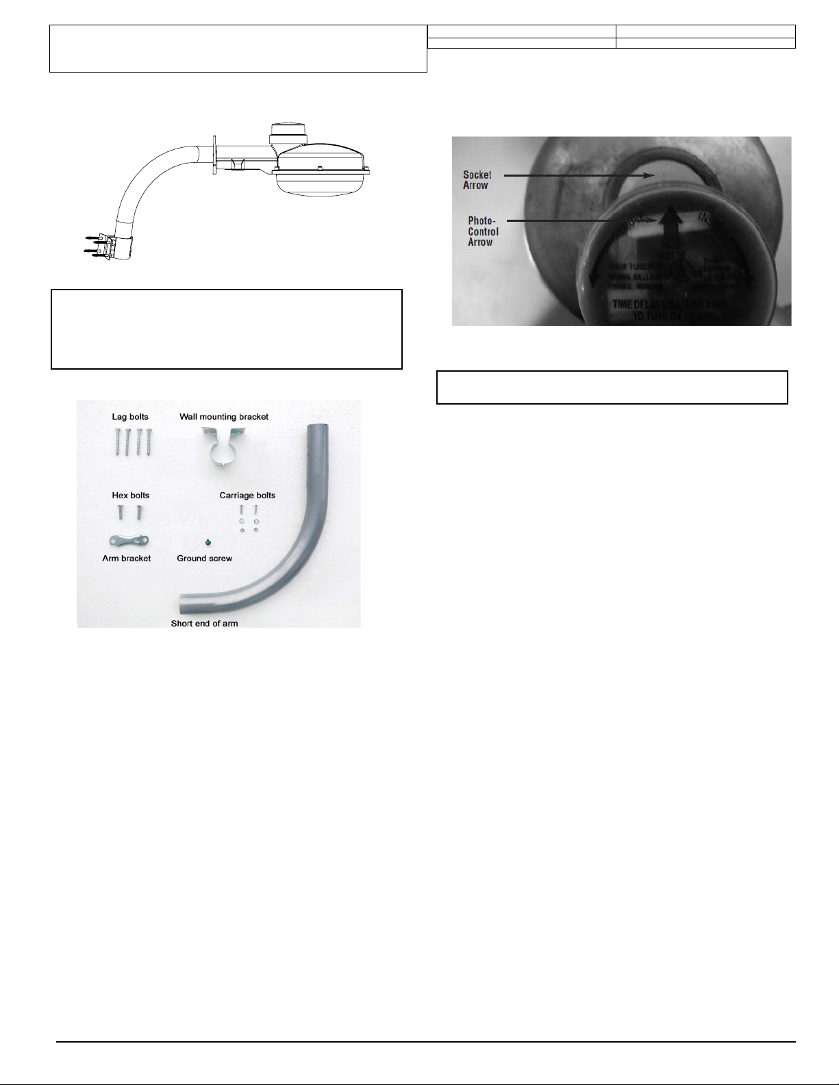
FIGURE 5: Arm Mounting Components
1. Loosely install (2) carriage bolts with lock washers and nuts
into wall mount bracket.
2. Install wall mounting bracket to mounting surface with (4)
Lag bolts a provided.
3. Insert short end of arm into mounting bracket. Adjust to
desired direction and tighten carriage bolts.
4. Feed (Customer Supplied) Ground wire up through arm.
5. Feed black and white xture wires down through arm.
6. Using (2) Hex bolts and arm bracket, secure housing to
arm.
NOTE: When installing the housing on to the arm, allow
1/4” (6.4 mm) spacing between end of arm and the housing
to prevent ground wire from being pinched.
7. Install (1) green ground screw onto arm bracket at location
marked “GND” and tighten ground screw to ground wire.
8. Wire black xture lead to the incoming hot lead and the
white xture lead to the incoming neutral (Common) lead.
9. Install the photo-control by aligning the arrow on the top
of the photo-control with the arrow on the photo-control
socket and inserting pins into the socket. Twist photo-
control clockwise until the arrow on the photocontrol is
pointing north. (Photocontrol must be rotated at least 1/8
turn to properly lock in place).
NOTE: Improper installation of the photo-control may result
in damage to the photo-control.
FIGURE 6- Photo-control Installation
FIGURE 4


