e-motion i3 Metal Motion User manual

ASSEMBLY INSTRUCTIONS
Documentation version 1.1.0

/ 2
Version 1.1.0
INTRODUCTION

/ 3
Version 1.1.0 Version 1.1.0
• Target :
Provide a visual guide of the various steps required to assemble the
«i3 Metal Motion» 3D printer.
• Designers of the i3 Metal Motion :
eMotion Tech : http://www.emotion-tech.com
Hugo FLYE
Mohamad KOUBAR
Tom LOPEZ
• Author of this document :
eMotion Tech : http://www.emotion-tech.com
Anthony BERNA
• Photographics credits :
Pictures and 3D representations made by eMotion Tech :
http://www.emotion-tech.com
• Sources :
http://reprap.org/wiki/reprap
• Licenses :
i3 Metal Motion : CC BY-NC-SA 4.0
This document : CC BY-NC-SA 4.0
http://creativecommons.org/licenses/by-nc-sa/4.0/
• Update :
Last update : 07/02/2018
• Useful links :
You can nd more informations on the following links :
eMotion Tech’s website : http://www.emotion-tech.com
RepRap community : http://reprap.org/wiki/reprap
INTRODUCTION

INTRODUCTION / 4
Version 1.1.0
INTRODUCTION 2
INTRODUCTION 3
SUMMARY 4
PRESENTATION OF THE I3 METAL MOTION 5
SAFETY INSTRUCTIONS 6
BILL OF MATERIAL 7
A. Metallic parts 7
B. Mechanical parts 7
C. Plastic parts 8
D. Hardware 8
E. Electronic parts 9
F. Extruder kit 9
G. Hexagon kit 10
H. Cables and extensions 10
I. Other 10
MECHANICAL ASSEMBLY 11
LCD screen 12
Electronic board 13
IEC connector 14
Reset button 16
Y axis (part 1) 17
Stabilized power supply 19
Y axis (part 2) 20
Y axis carriage 23
Y axis belt 25
Y Axis plate 27
Z Axis right side carrriage 32
Z Axis left side carriage 35
Print head 36
X axis carriage 38
Z axis assembly 46
X axis assembly 53
Auto-leveling probe assembly 65
ELECTRONIC ASSEMBLY 66
SUMMARY

/ 5
Version 1.1.0 Version 1.1.0
PRESENTATION OF THE I3 METAL MOTION
The latest creation of the eMotion Tech company, the I3 Metal Motion
promises stability and accuracy.
With all our knowledge and experience acquired with our previous
printers, we wanted to propose an elegant and reliable solution
to the problems encountered on many 3D printers on the market.
The I3 Metal Motion will seek to become a symbol of durability and
robustness, a precision tool at your disposal.
The I3 Metal Motion is, rst of all, a solid steel frame that makes it easy
to build in compare to any classic I3, with a low number of components.
We have searched to develop a heavy and solid structure, including
reinforcements in order to minimize vibrations and maximize the stability.
A sharper and reliable extrusion
The whole extrusion system is mounted on a steel carriage that
avoids the distortions that most of the plastic parts are victims. For
a higher ergonomics and quality, we have brought our solutions :
- a disengageable extruder to take o or engage the lament with a
simple ngers pressure.
- Manual extrusion of the lament made by a molded wheel to have a
very sharp ow.
- No clearances or empty space on the path of the lament, so it’s
possible to print with every kind of lament available on the market
(PLA, ABS, G-l, G-Carbon, eMotion Flex...)
Here are the features of the I3 Metal Motion :
• Dimensions : Height 440mm, Width 400mm, Depth 430mm
• Print volume : 200x200x200mm
• Thickness of the layers : from 100 to 350 microns
• Compatible laments : 1.75mm diameter, PLA, ABS, G-Fil, M-Fil, Flex
• Heating bed : yes, up to 110 ° C.
• Rated print speed : > 80mm / s
• Maximum movement speed : 200mm / s
• Nominal movement speed : 150mm / s
• Average accuracy (X, Y) : 100 microns
• Average accuracy (Z) : 50 microns
• Electronics type : eMotronic and TF card
• Microcontroller : LPC1768, 32-bit ARM Cortex-M3 at 100MHz
• Print with Hexagon 1.75mm extrusion head (interchangeable nozzles)
• Nozzle outlet : Ø 0.4 mm by default (modiable a posteriori)
• Operating System : Win XP, Vista, 7, 8, 10, Ubuntu 12+, Mac OS X
• USB connectivity
• Interfacing : LCD screen with TF card reader
• Power supply : 24 Volts / 320 Watts
The kit includes :
All the spare parts of the kit
A spool of 500 grams of PLA

INTRODUCTION / 6
Version 1.1.0
SAFETY INSTRUCTIONS
General safety instructions
The nozzle can reach 270°C, do not touch the nozzle while the printer is
working.
A supervisor is needed when the printer is used with young people.
KEEP PRINTER AWAY FROM CHILDREN AND ANIMALS
Operate in a ventilated room. Plastic vapors eets are not known. In
case of use in a closed room, we recommend the use of an extractor fan.
The addition of protections is your own responsibility. Safety can be
improved by :
• Housing protection
• Smoke detector
Electrical safety
The power supply provided is labelled CE. The power supply is protected
against short-circuit and do not need any modication. The I3 Metal
Motion operate at 24V and is not concerned by the low voltage directives.
Further informations
Informations above are not exhaustive.
We used sources of informations that we consider reliable. However, we
cannot guarantee that all these informations are true and complete.
We assume no liability for loses, injuries or damages due to assembly,
transporting, storage or removal of the product.
NEVER LEAVE THE PRINTER WORKING WITHOUT
SUPERVISOR.

INTRODUCTION / 7
Version 1.1.0 Version 1.1.0
BILLS OF MATERIAL
A. Metal parts
1 x Lower part
4 x Rod Ø 8 x 290 mm
2 x Rod Ø 8 x 360 mm
1 x Frame 2 x Reinforcement 1 x Y axis carriage 1 x Y axis plate
1 x Z axis carriage
right side
1 x Z axis carriage
left side
1 x X axis carriage
B. Mechanical parts
2 x Ø 8 mm lead screw
2 x Trapezoidal nut drive
2 x Coupling 3 x Linear bearing block 4 x Flanged linear
bearing

INTRODUCTION / 8
Version 1.1.0
D. Hardware
10 x M2,5 x 8 mm screw
5 x M2,5 x 12 mm screw
50 x M3 x 8 mm screw
30 x M3 x 12 mm screw
25 x M3 x 20 mm screw
4 x M3 x 22 mm screw
20 x M4 x 6 mm screw
15 x M3 nut
15 x Ø 3 mm x height 3 mm spacer
5 x Ø 3 mm x height 5 mm spacer
5 x Ø 3 mm x height 10 mm spacer
13 x Ø 3 mm washer
2 x GT2 pul-
ley
2 x GT2 belt 2 x Idler pulley kit
C. 3D printed parts
1 x Fan duct 1 x Y axis belt
holder
1 x X axis belt
holder
4 x Y axis rod
holder
4 x Z axis rod
holder
4 x X axis rod
holder
1 x Hexagon
bracket
1 x PTFE tube
1 x Leveling
sensor holder
1 x Filament
guide
INTRODUCTION / 9
Version 1.1.0 Version 1.1.0
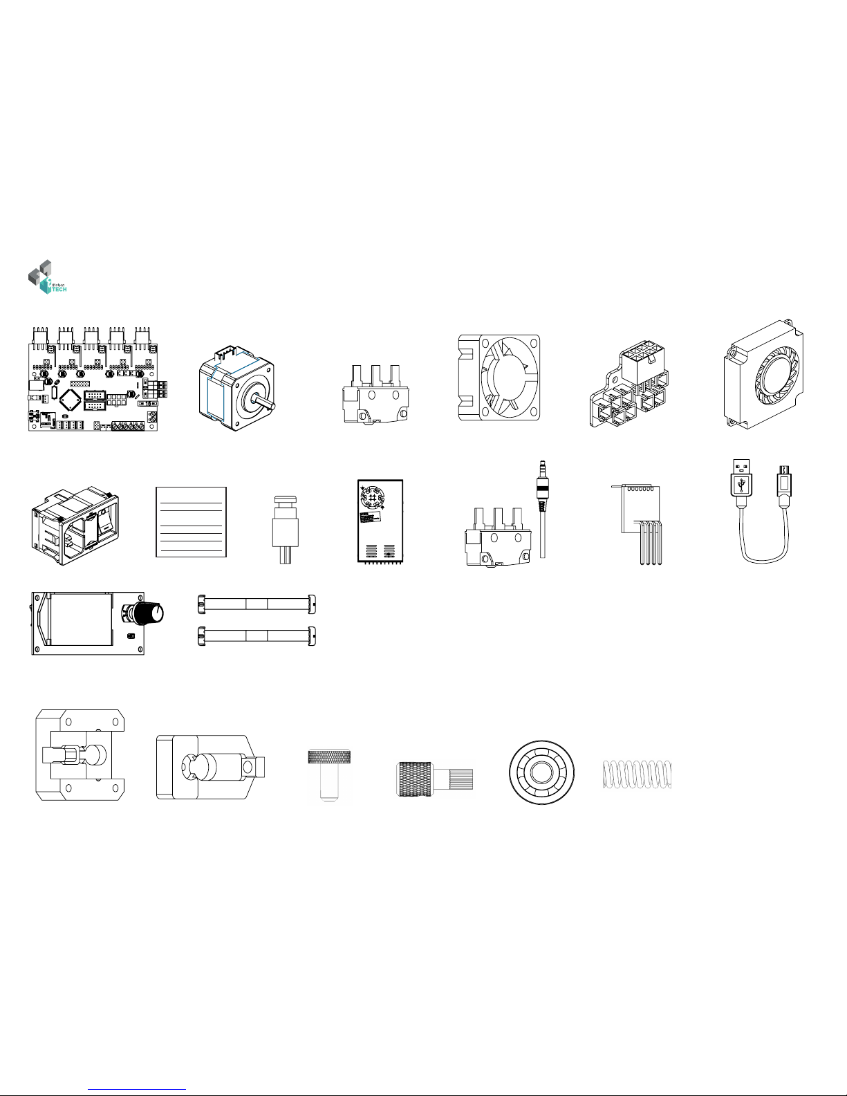
E. Electronic
F. Extruder kit
1 x eMotronic
1 x TF Card
5 x Nema 17 Motor 3 x Endstop
(colored connector)
1 x 3 cm fan
1 x Power supply
1 x EBoard
1 x IEC connector 1 x Reset button
1 x Body
extruder
1 x Mobile
extruder
1 x M5 x 12 mm
knurled screw
1 x Driving wheel 1 x 693zz
bearing
1 x Spring
1 x Calibration probe 1 x USB cable
1 x Blower fan
1 x Heating patch 1 x Motor driver
1 x LCD screen
and TF card reader
2 x Ribbon cable
INTRODUCTION / 10
Version 1.1.0
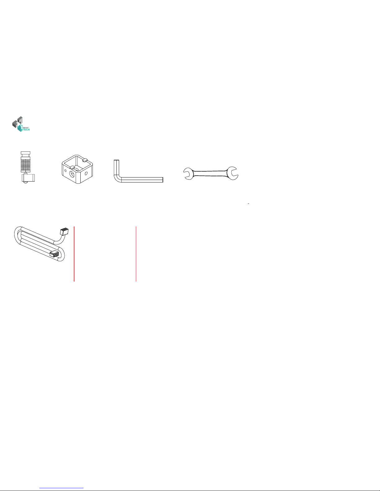
G. Hexagon kit (hotend)
1 x Hexagon hotend 1 x 3 Allen key 1 x 4.5 wrench1 x Silicon sleeve
H. Cables and extensions
I. Autres
• 1 x bag of grease
• 1 x bag of zip ties
1 x 20 mm motor’s cable
2 x 50 mm motor’s cable
1 x Thermistor
1 x Heater cartridge
1 x Blue endstop
4 x Power supply cable
1 x Reset button
2 x IEC On/O cable
1 x IEC VCC cable
1 x IEC GND cable
1 x IEC EARTH cable
1 x JACK endstop
1 x Extruder extension
1 x Z carriage extension
2 x endstop
1 x 220V power supply cable
1 x Mini USB cable

MECHANICAL ASSEMBLY / 11
Version 1.1.0 Version 1.1.0
MECHANICAL ASSEMBLY

MECHANICAL ASSEMBLY / 12
Version 1.1.0
ASSEMBLY OF THE LCD SCREEN
Target : mount the LCD screen on the lower part
Needed parts :
• Lower part
• LCD screen
• LCD button
• 4 x M3 x 12 mm screw
• 4 x Ø3 x H5 spacer
• 4 x M3 nut
M3 x 12 mm
Ø3 x H5 spacer
M3 nut
LCD screen
Lower part
Result
Result
LCD button
!
Do not tighten the
screws too much,
otherwise the LCD
screen may be
damaged

MECHANICAL ASSEMBLY / 13
Version 1.1.0 Version 1.1.0
ASSEMBLY OF THE ELECTRONIC BOARD
Target : mount the electronic board on the lower part
Needed parts :
• Lower part
• eMotronic board
• 4 x M3 x 8 mm screw
• 4 x Ø3 x H3 spacer
M3 x 8 mm screw
eMotronic board
Ø3 x H3 spacer
Result
MECHANICAL ASSEMBLY / 14
Version 1.1.0
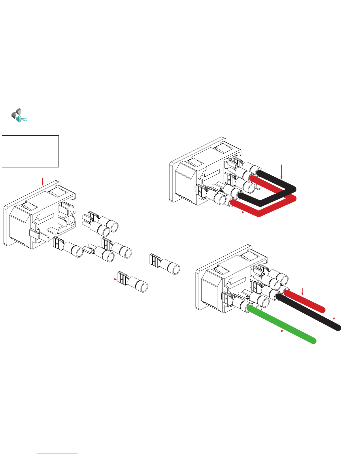
ASSEMBLY OF THE IEC CONNECTOR
Target : preparation of the two cables of the IEC connector
Needed parts :
• Lower part
• IEC connector
• 2 x Short strap cable
Short strap cable
IEC connector
Insulated pod
Green cable = GND
Red cable
=
phase
Black cable
=
neutral
Short strap cable
in black on the illustration for the
visibility but red in IRL
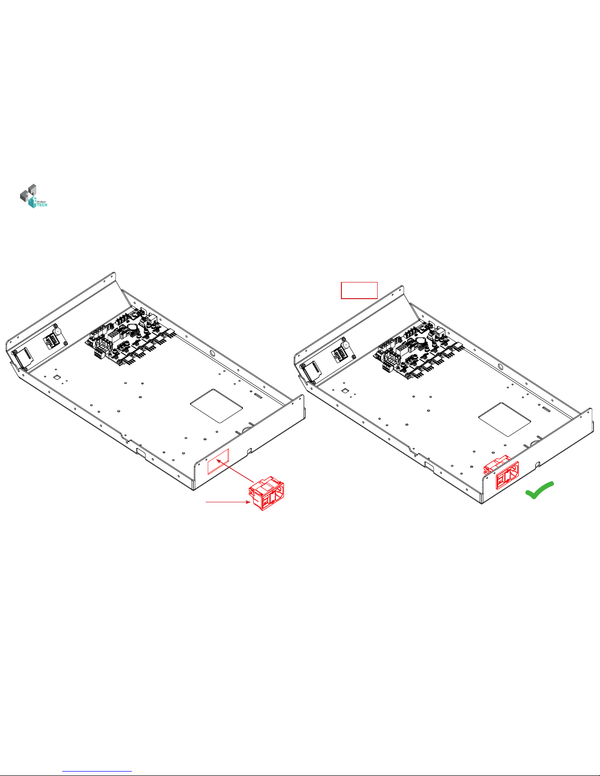
MECHANICAL ASSEMBLY / 15
Version 1.1.0 Version 1.1.0
IEC connector
«Clips»
Result
Target : mount the IEC connector on the lower part
Black cable
=
neutral
MECHANICAL ASSEMBLY / 16
Version 1.1.0
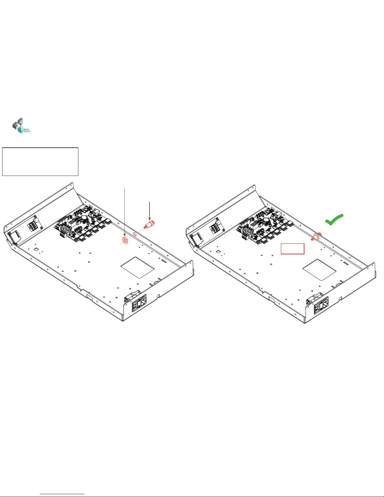
ASSEMBLY OF THE RESET BUTTON
Target : mount the reset button on the lower part
Needed parts :
• Lower part
• Reset button
Result
Reset button
Button nut

MECHANICAL ASSEMBLY / 17
Version 1.1.0 Version 1.1.0
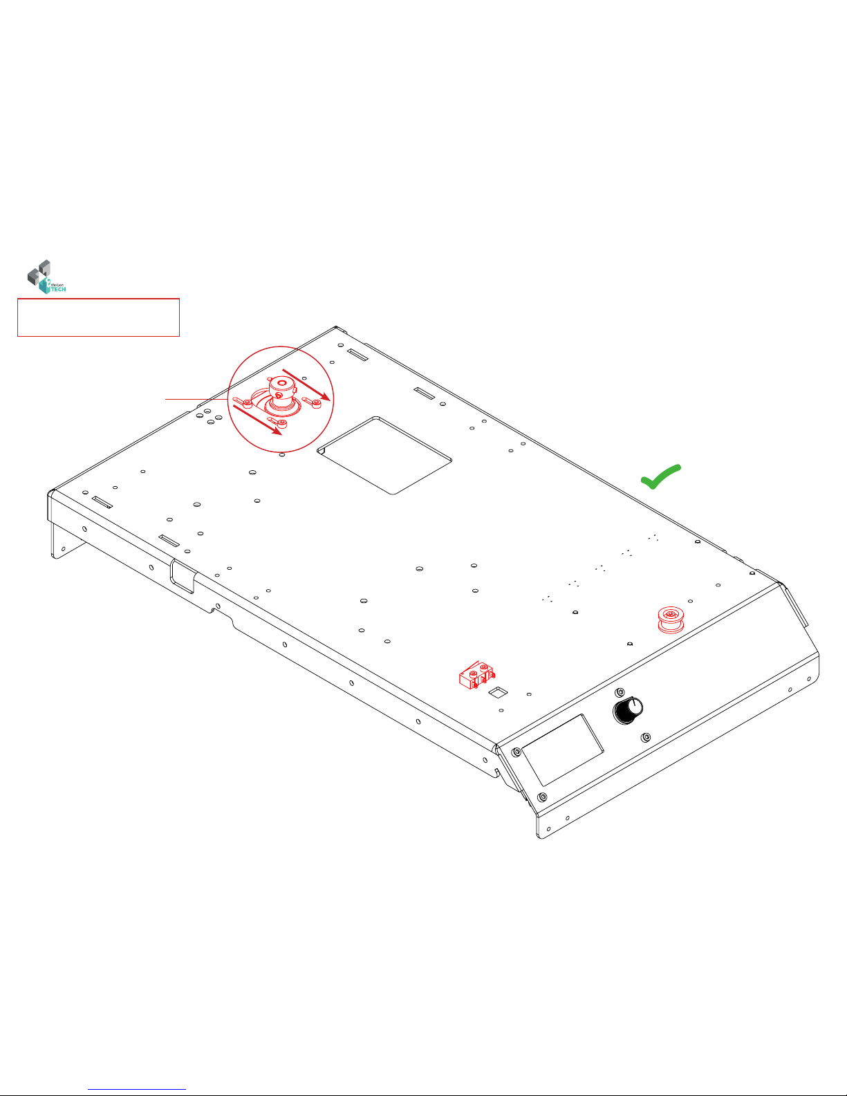
ASSEMBLY OF THE Y AXIS (part 1)
Target : mount the motor, pulleys and the Y axis endstop on the lower part
Needed parts :
• Lower part
• Nema 17 motor
• Blue endstop
• GT2 pulley
• Idler pulley
• Pulley bearing
• 4 x M3 x 8 mm screw
• 1 x M3 x 12 mm screw
• 2 x M2.5 x 8 mm screw
• 2 x Ø3 x H3 spacer
• 4 x Ø 3 mm washer
The grub screw must be in
contact with the at part of the
axis.
M3 x 8 mm screw (do not tighten the motor screws for the moment)
GT2 pulley
NEMA 17 motor
M2.5 x 8 mm screw
M3 x 12 mm screw
Idler pulley
Pulley’s bearing
Ø3 x H3 spacer
!
Connector’s
orientation
!
Lamella’s
orientation
Flat side
Screw
3 mm
Ø 3 mm washer
Blue endstop
MECHANICAL ASSEMBLY / 18
Version 1.1.0
RESULT
The motor must be
positioned towards the
front of the machine

MECHANICAL ASSEMBLY / 19
Version 1.1.0 Version 1.1.0
ASSEMBLY OF THE POWER SUPPLY
Target : mount the power supply on the lower part
Needed parts :
• Lower part
• Power supply
• 4 x M4 x 6 mm screw Result
M4 x 6 mm screw
!
Power supply
orientation
MECHANICAL ASSEMBLY / 20
Version 1.1.0
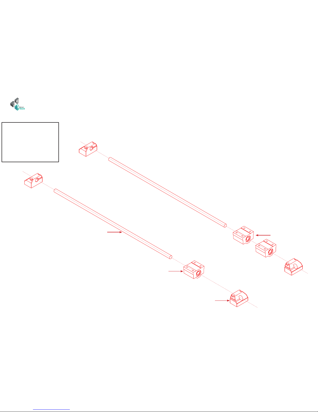
ASSEMBLY OF THE Y AXIS (part 2)
Target : mount rods, bearing blocks and holders on the lower part.
Needed parts :
• Lower part
• 4 x Y axis rod holder
• 2 x 8 x 360 mm rod
• 3 x Linear bearing block
• 8 x M3 X 20 mm screw
8 x 360 mm rod
1 linear bearing block
Y axis rod holder
2 linear bearing rod
Table of contents


