E-ronix ESC-200J Owner's manual

Installation and Operation
Joystick System Controller
■ ESC-200J / ESC-200JW

2
CONTENTS
Contents
General Information
Function Description ...……………………………..…………………………3
Scope of Delivery ………………………………..……………………………3
Safety Precautions ………..……………..……..…………………….………4
Connection and Configuration
System Overview ……………………………………………….……….…..5
Connecting the Keyboard …..………………………………………….……7
▪ Power Supply ……………………………………..……………………….8
▪ RS485 Interface …………………………………..……………………….8
Operation
Key Assignment …………………………………..……………………………9
General Operation ………….…………….……………………………….....11
Protocol/Baud Selection ...……….…………….………………………….....11
Joystick Control ………….…………….……………………………….....10
Exhibit
Troubleshooting ……………………………….….…………………………12
Technical Specifications ………………….……………….………………..13
Dimension ……………………………………..……………..………………14

3
GENERAL INFORMATION
General Information
Function Description
T
his external keypad controller is used for the controlling, monitoring
and programming of RS485 system products.
Due to its compact size, it can be integrated everywhere
harmoniously. With this keypad controller, you can control single
components as well as complexCCTV systems. Clients within the
RS485 BUS are selected via the numeric keypad. Contact with the
corresponding client is confirmed by an acoustic signal and
additionally in the keypad’s info display. Messages such as target
address, type of receiver and e.g. camera movements are also shown in
the display.
I
f you are using a matrix switcher, this is selected as central unit.
Connected pan/tilt heads or high speed dome cameras are
automatically enabled for control by the offset function integrated into
the matrix switcher. It is not necessary to additionally address them
directly.
T
his keypad controller comes with a robust joystick with integrated
zoom function (effected by turning the joystick). This makes it be
possible to control connected pan/tilt head camera stations
respectively high speed dome cameras reliablyand easily. Just one
hand is required for tracking an object with the connected camera unit.
A
potential separation with an optic-coupler (potential separator)
allows trouble-free data communication on the RS485 control line.
Scope of Delivery
▪ Remote control unit
▪ 3 m connection cable
▪ Power adapter 230/110 VAC to 12 VDC
▪Junction box
▪Operation manual

4
GENERAL INFORMATION
Safety Precautions
1. Read these instructions carefully before connecting the
components in order to avoid malfunctions and damages caused
by improper installation or use.
2. Installation may only be carried out by authorized personnel
according to the local safety regulations.
3. Only operate the device with the included power supply adapter
and the stated operating voltage.
4. Never use the camera for other purposes except that designated.
5. Repairs and adjustments at the device may only be carried out by
authorized personnel.
6. Remove the device from power supply if you do not use it for an
extended period of time.
7. Immediately disconnect the device from power supply if any liquid
or solid matter should get into the housing and have it checked by
your authorized dealer before re-using.
8. Follow the warning notes attached to the device.
9. Only use the device in dry, dust-free and non hazardous locations.
10. Only use the device indoors.
11. In order to avoid internal heat accumulation in the device:
- do not expose the device to direct sunlight.
- keep sufficient distance to direct heat sources.
5
CONNECTION AND CONFIGURATION
Connection and Configuration
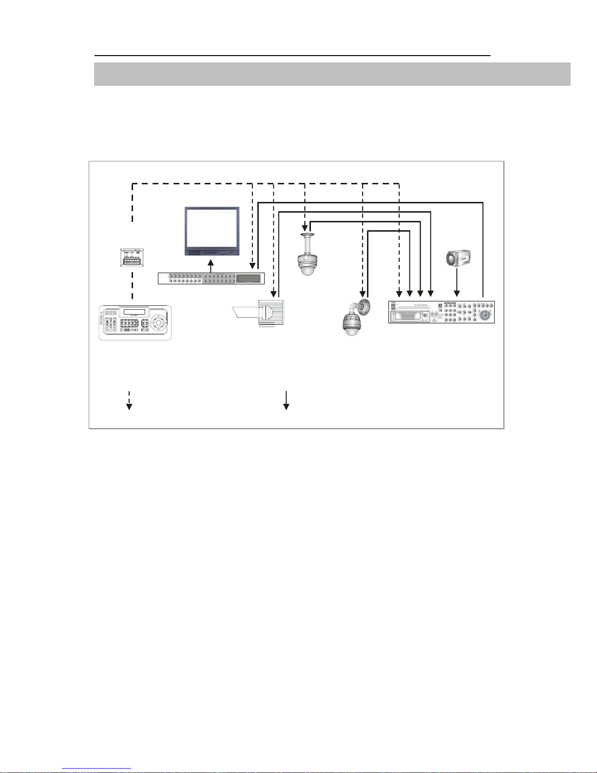
System Overview
A. Standard Connect
RS-485 SIGNAL FLOW VIDEO SIGNAL FLOW
The following devices can be controlled with this keypad controller:
- Telemetry receiver for pan/tilt head
- Telemetry receiver for pan/tilt head with pre-set positions
- High speed pan/tilt head
- High speed dome for indoor use
- High speed dome for outdoor use
- Video matrix switcher (operation via RS485/232C)
- Digital video recorder for High speed domes (operation via RS485)
- The Controller manages directness the High speed domes
Controller Pan/Tilt Head
Dome
(Indoor)
Dome
(Outdoor) DVR
Matrix Switcher
Junction
Box CCD
Monitor
DVR

6
CONNECTION AND CONFIGURATION
B. Control via DVR Connect
RS-485 SIGNAL FLOW VIDEO SIGNAL FLOW
The following devices can be controlled with this keypad controller:
- Telemetry receiver for pan/tilt head
- Telemetry receiver for pan/tilt head with pre-set positions
- High speed pan/tilt head
- High speed dome for indoor use
- High speed dome for outdoor use
- Video matrix switcher (operation via RS485/232C)
- Digital video recorder for High speed domes (operation via
RS485/232C)
- The Controller uses DVR and indirectness it manages the High speed
domes
Controller
Dome
(Indoor)
Dome
(Outdoor)
DVR
Matrix Switcher
Junction
Box CCD
Monitor
DVR

7
CONNECTION AND CONFIGURATION
Connecting the Keyboard
The clients are connected in a parallel way to the RS485 line
(conductors A and B). Up to 32 clients with a max. connection length
of 6 m can be connected to the main line.
The RS485 line can have a length of up to 1200 m. A transmission line
with 120 Ohm has to be connected to the start and to the end of it in
order to avoid signal reflections. The terminating resistor for the RS485
can be connected to each client with a jumper.
A
A
B
B
CL 1 CL 2 CL(n-l) CL n
CL = Client
120Ω120Ω
Start 1200m End

8
CONNECTION AND CONFIGURATION
PACKING DETAIL
Only operate the device with the power supply adapter (12VDC)
included in the scope of delivery. Connect the power supply adapter to
the keyboard’s junction plug into the connector box.
The correct power supply is signaled by the LCD display.
- RS485 Interface
- Power supply
Connect the RS485 interface with correct polarity (TRX+ and TRX-) to
the junction box.
1. CONTROLLER
2. JUNCTION BOX 3. MANUAL 4. AC ADAPTOR
& POWER CORD
5. RJ45 CABLE (3m, 50cm)
DVR

DVR
9
OPERATION
Operation
This keypad controller can control all of RS485 devices. The
corresponding key commands for controlling the individual devices are
described in this chapter.
Key Assignment
Number Description
1 LED Display. Power, Master Tx/Rx, Slave Tx/Rx.
2 Master/Slave RJ-45 Ports.
3-a CAM key. Camera or Dome selection key.
3-b DVR key. DVR selection key.
3-c MON key. Monitor(Matrix switcher) selection key.
4 Numeric buttons.
Left, Right, Up and/or Down functions with SHIFT on.
5 ESC/CLEAR key. Exit without Saving function in menu.
6 ENTER/SELECT key. Save and Exit in menu.
7 Special function keys.
8-a, 8-b
8-c, 8-d PRESET/TOUR/PATTERN/SCAN key.
See Operation part in this manual for details.
9 Function key. Hot key functions.
10 CONTROL key. Various functions with CTRL key pressed.
11 SHIFT key. Various functions while SHIFT is on.
12 SETUP key. Enters Controller Setup menu.
13 MEMU key. Enters Camera/Dome Setup menu.
14 FOCUS NEAR/FAR keys.
15 IRIS OPEN/CLOSE keys.
ENT/ESC function in some protocols
16 ZOOM TELE/WIDE keys.
17 JOYSTICK. Pan/Tilt/Zoom Operation.
①
④
⑤
②
3-a 3-b 3-c
8-a 8-b 8-c 8-d
⑥
⑦
⑨
⑩⑪⑫⑬
⑭
⑮
16
17
10
OPERATION
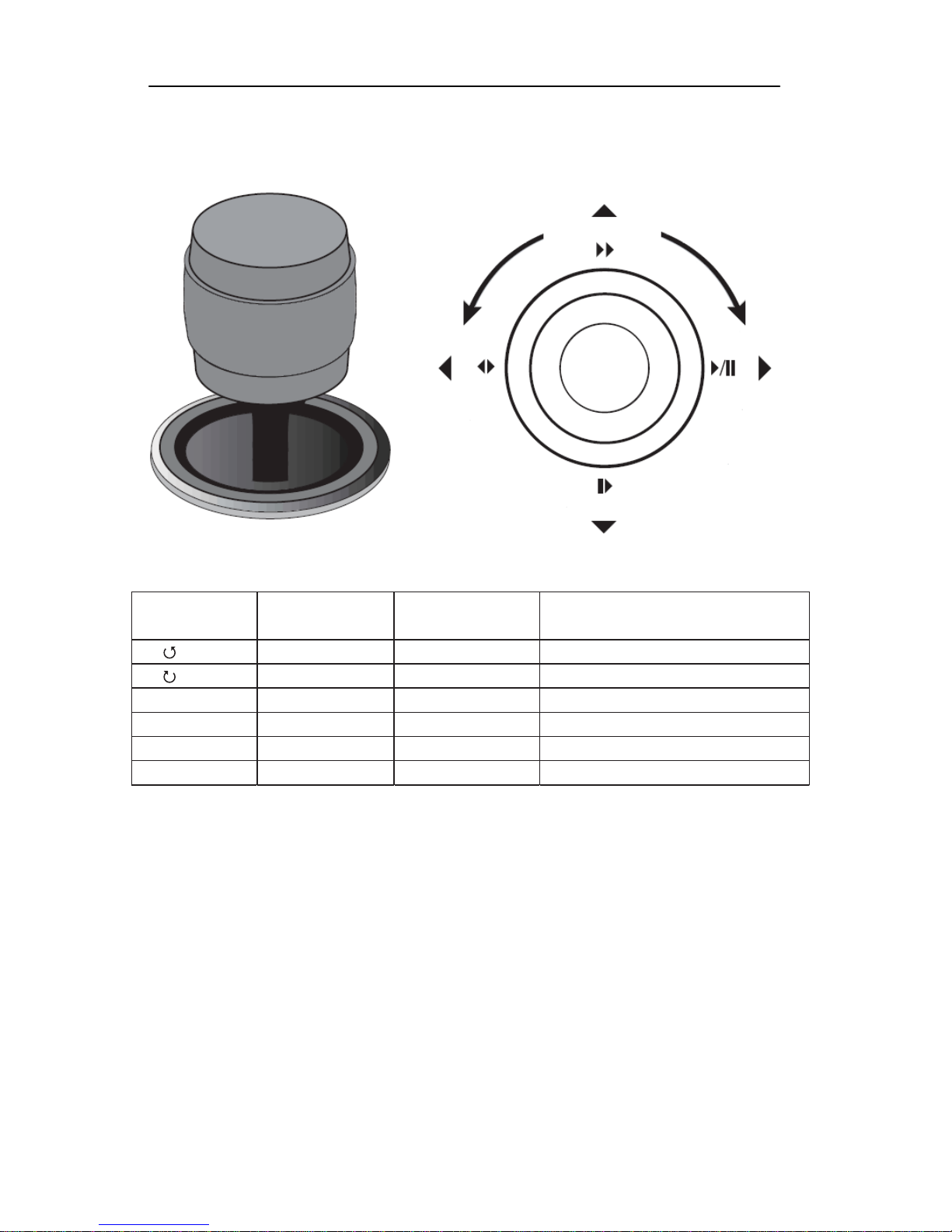
Joystick Control
Joystick
Control Operation State Description
①ZOOM WIDE PTZ PTZ Zoom TELE
②ZOOM TELE PTZ PTZ Zoom WIDE
③▲ ▲ Menu setup Upper direction
④▼ ▼ Menu setup Lower direction
⑤◀ ◀ Menu setup Left direction
⑥▶ ▶ Menu setup Right direction

11
OPERATION
General Operation
Protocol/Baud rate Selection
Function Procedure
LED LED shows the power on, shift lock or Tx/Rx status.
Enter Press ENT to select a number that has been entered. In Menu Mode, goes to previous
menu with saving.
Clear Press ESC to cancel a number that has been entered. In Menu Mode, goes to previous
menu without saving.
Control If you move the joystick with CTRL key pressed, the slowest speed of pan, tilt or zoom
is applied.
Shift Press SHIFT to allow the numeric keyboard to send left, right, up or down commands.
If you move the joystick with this key pressed, the fastest speed of pan, tilt or zoom is
applied.
Select Camera LCD display shows camera number in CAMERA mode.
Enter camera number and press CAM to select.
Select DVR Enter DVR number and press DVR to select.
Select Monitor Enter monitor number and press MON to select.
Pan/Tilt/Zoom Move the joystick until the camera reaches the desired position. To increase
the speed of movement, move the joystick further from center. Twist the joystick
clockwise to zoom in(tele), counterclockwise to zoom out(wide).
Enter a CAMERA address (1-999) and the press SETUP key.Use numeric keys or joystick to select a protocol
and/or baud rate.
TURBO speed: Move the joystick with SHIFT key pressed.
Slowest speed: Move the joystick with CTRL key pressed.
Lens Control
(focus/iris) Focus, iris - Press and hold the appropriate lens control key until the desired effect is
seen.
Presets Program
Position camera and then enter desired preset number (1-240) and hold down PRST for
two seconds.
Call
Enter preset number (1-240) and press PRST to put camera in preset position.
Clear
Enter desired preset number (1-240) and press PRST with CTRL key pressed.
Patterns Program
Enter a pattern number (1-8) and hold down PTRN for two seconds. The monitor will
indicate the programming function is active. Move the camera position as desired for the
pattern.
To save and exit the programming function, hold down PTRN for two seconds.
Call (Run)
Enter a pattern number and press PTRN. Move the joystick or call a preset to stop.

12
EXHIBIT
Exhibit
Trouble shooting
Please contact your authorized dealer with an exact failure description if
none of the below mentioned remedy measures fixes your problem.
ErrorDescription Cause
No function - Not plugged in
- Connects plug of the keyboard controller
not connected
- Incorrectly switched 120 Ohm
termination resistor
No communication
via RS485 interface - Incorrectly assigned device address of
the client
- Fault in the client’s power supply
- Missing or incorrect cable
- Incorrectly switched 120 Ohm
termination resistor
System crash - If twisted pair line is not shielded,
interference may occur
- Moving loads are plugged incorrectly
- Power supply of one (several) clients is
defective

13
EXHIBIT
Technical Specifications
Application RS485 transmitter for selection and control of a
maximum of 100 RS485 clients with an unlimited
number of control commands
Joystick Yes (pan/tilt move and zoom wide/ tele control)
Display 16 characters x 2 line LCD
Housing Connection cord Table desk housing
6 cores, 5m long, pre-assembled with Western plug
Operating voltage 12V DC
Consumption 1.4 W (7V DC)
Addressing Adjustable via jumper or software
Output RS485 interface / BUSTRONIC protocol
Operating temperature -10° C up to + 55° C
Air humidity < 90 %
IP rating / class IP40 / Class III
MTBF 80,000 hours
EMI / EMC / Safety FCC / CE
Dimensions (W x H x D) 342 x 165 x 96.8 mm
Housing color ABS / Black
Accessories (included) operating instructions, Western socket
Weight About 690g
14
DIMENSION
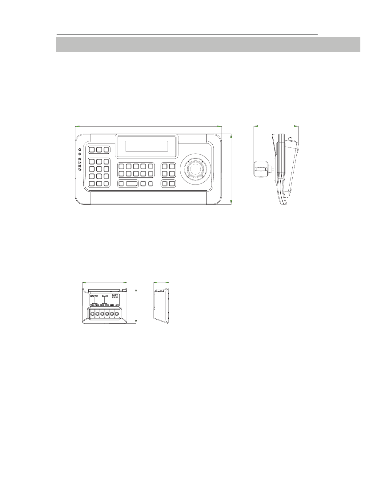
Dimension
A. System Controller
B. Junction Box
342.0
342.0
165.0
165.0
104.0
104.0
69.5
69.5
55.0
55.0
24.0
24.0
This manual suits for next models
1
Table of contents
Popular Security System manuals by other brands

Bosch Security
Bosch Security PoE midspans installation manual

Pro-tec
Pro-tec SYSTEM ONE PTS-2 user manual

Abus
Abus Alarmbox 2.0 quick start guide

Q-See
Q-See QC804-261-1 NVR Product information

Scantronic
Scantronic HOMELINK EXTRA Programming guide

Security Command
Security Command XR20 Executive Series user guide


