EnglishDeutsch
 logo
Brands
  1. Home
  2. •
  3. Brands
  4. •
  5. Innohome
  6. •
  7. Security System
  8. •
  9. Innohome SGS1030 User manual

Innohome SGS1030 User manual

Other Innohome Security System manuals

Innohome Stove Alarm SA100 User manual

Innohome

Innohome Stove Alarm SA100 User manual

Innohome Stove Alarm SA101 User manual

Innohome

Innohome Stove Alarm SA101 User manual

Innohome Smart Socket SSC100 User manual

Innohome

Innohome Smart Socket SSC100 User manual

Innohome Stove Alarm SA101 User manual

Innohome

Innohome Stove Alarm SA101 User manual

Innohome Stove Guard 300 User manual

Innohome

Innohome Stove Guard 300 User manual

Innohome SGK510 Stove Guard User manual

Innohome

Innohome SGK510 Stove Guard User manual

Innohome SA102RF User manual

Innohome

Innohome SA102RF User manual

Popular Security System manuals by other brands

Inner Range Concept 2000 user manual

Inner Range

Inner Range Concept 2000 user manual

Climax Mobile Lite R32 Installer's guide

Climax

Climax Mobile Lite R32 Installer's guide

FBII XL-31 Series installation instructions

FBII

FBII XL-31 Series installation instructions

Johnson Controls PENN Connected PC10 Install and Commissioning Guide

Johnson Controls

Johnson Controls PENN Connected PC10 Install and Commissioning Guide

Aeotec Siren Gen5 quick start guide

Aeotec

Aeotec Siren Gen5 quick start guide

IDEAL Accenta Engineering information

IDEAL

IDEAL Accenta Engineering information

Swann SW-P-MC2 Specifications

Swann

Swann SW-P-MC2 Specifications

Ecolink Siren+Chime user manual

Ecolink

Ecolink Siren+Chime user manual

Digital Monitoring Products XR150 user guide

Digital Monitoring Products

Digital Monitoring Products XR150 user guide

EDM Solution 6+6 Wireless-AE installation manual

EDM

EDM Solution 6+6 Wireless-AE installation manual

Siren LED GSM operating manual

Siren

Siren LED GSM operating manual

Detection Systems 7090i Installation and programming manual

Detection Systems

Detection Systems 7090i Installation and programming manual

Se-Kure Controls MicroMini SK-4841 instructions

Se-Kure Controls

Se-Kure Controls MicroMini SK-4841 instructions

Siemens FDM273 manual

Siemens

Siemens FDM273 manual

DSC PC 4010 Programming manual

DSC

DSC PC 4010 Programming manual

UniPOS 6202L quick start guide

UniPOS

UniPOS 6202L quick start guide

AJAX DoubleButton user manual

AJAX

AJAX DoubleButton user manual

Rondish Nexus User instructions

Rondish

Rondish Nexus User instructions

https://manuals.online logo
https://manuals.online logoBrands
  • About & Mission
  • Contact us
  • Privacy Policy
  • Terms and Conditions

Copyright 2026 Manuals.Online. All Rights Reserved.

For indoor use only.
Do not use in a
professional kitchen.
REFERENCE AND
INSTALLATION
MANUAL
INNOHOME
STOVE ALARM
SGS1030
770-00090-A1
Innohome Stove Alarm is a safety product for domestic kitchens. The Stove Alarm
is a state-of-the-art heat sensor that monitors the stove (or the range) from the top.
Ensure to read this manual prior to starting installation.
TECHNICAL SPECIFICATIONS 3
INSTALLATION 4–7
GETTING STARTED 8
ACTION IN AN EVENT OF AN ALARM 8
FREQUENTLY ASKED QUESTIONS 9
SETTINGS 10
FUNCTION TEST 11
NOTICES 12
CONTENTS
Thank you for choosing Innohome Stove Alarm!
Safety rules
Stove Alarm helps to prevent potentially dangerous situations, and it makes the use of
the stove safer.
Never leave the stove unattended. Always check compliance with local regulations.
• For indoor use only.
• Do not use in a professional kitchen.
• Do not hold the Stove Alarm close to the ear. It can
cause hearing damage when in alarm or test mode.
• Do not leave children alone with the product or any
of its parts or packaging. There is a risk of choking.
• Do not disassemble the product.
• Do not immerse the Stove Alarm in water.
• The Stove Alarm will not emit an alarm if the
temperature of the stove is too low to identify a
dangerous situation, or if the stove has an automatic
limitation of temperature increase.
• Do not short-circuit, charge, open or heat the
battery. There is a risk of explosion.
2
3
IR lens
(Lens extension for
high installations)
Button
Signal LED
should face towards user
TECHNICAL SPECIFICATIONS
Battery lid
The Stove Alarm is a battery-
operated device. Use only new
CR2302 button cell (watch type)
batteries. To avoid damage or mal-
function, do not use other types.
Pull out the battery lid. Place the
battery under the lid, and slide
the lid back in. Make sure that
“the plus side”comes upwards
(towards the battery lid). The
Stove Alarm makes a“beep”
when the battery is inserted
correctly. Replace the leaking
battery immediately.
SGS1030 Stove Alarm
• Nature of supply: Battery operated
(CR2302 Button Cell, 3V DC)
• Sensor Dislocation Alarm
• Adjustable sensitivity levels (learning)
• Audible alarm signal min. 65 dB(A),
max. 80 dB(A) @ 40’’ (100cm)
• Sensing distance (from the range top)
18’’–32’’ (45–80cm) OTR/range hood installation
• Flame retardant and high heat resistant plastics,
UL recognition 94 V-0
• Wireless 315 MHz/10mW RF
• Operating ambient temperature:
32 °F to 95 °F ( 0 °C to 35 °C)
• Intended transportation condition of control:
14 °F to 131 °F (-10 °C to 55 °C)
Applied standards
FCC Rule Part: 15.231:2017 (Periodic operation in the band
40.66-40.70 MHz and above 70 MHz)
IC Rule Part: RSS-210 Issue 9, 2017 and RSS-GEN Issue 5, 2018
U.S. Pat. Nos 10,051,993 and 10,347,112
Installation plate
with adhesive tape
Stove Alarm
OVER-THE-RANGE
MICROWAVE
Select the mounting location
Measure the installation height. The Stove Alarm should be centered
above the stove, preferably within Zone 1 (see the diagram below).
It can be attached to the grease lter. It is important to ensure the
minimum distance from the light underneath the hood is 4" (10cm)
(2" (5cm) is enough for LED lamp).
Zone 1 is recommended for best performance.
Mount the Stove Alarm
The Stove Alarm might beep at
this stage indicating that it is not
properly placed on the installa-
tion plate. As this happens, no
further action is required.
If there is a metal mesh grease
lter on the range hood, make
sure it is greaseless and dry. Press
at least for a minute from the
opposite side while attaching
adhesive.
Carefully remove the protective
lm from the installation plate.
Attach the Stove Alarm with the
LED facing the user.
Attach the installation plate
while the Stove Alarm is on it.
1 2
Zone 2
Zone 1 - Radius 6" (15cm)
Min 4" (10cm)
Min 2" (5cm)
for LED lamp
Zone 1 is immediately
above the middle of
the burners. Max 6"
(15cm) from the centre.
INSTALLATION
Zone 1
4
INSTALLATION UNDER
MICROWAVE
Allow the Stove Alarm to reach room temperature before use.
See the table below for the mounting location and follow instructions 1–4.
Starting the Stove Alarm
Insert the battery (see page 3)
and place the Stove Alarm on the
installation plate. Press the but-
ton shortly. (LED ashes green).
Check installation height
If the distance from stove to Stove Alarm is more than 24" (60cm), the
Stove Alarm's sensitivity level must be adjusted manually.
Please refer to the table underneath together with the information on
page 18, alternatively watch the lm on sensitivity conguration.
3 4
5
Watch the movie:
https://vimeo.com/321503955
Setting sensitivity
Watch the movie:
https://vimeo.com/321502592
Sensor installation
DISTANCE FROM COOKER
TO HEAT SENSOR
COOKER SIZE SENSITIVITY LEVEL CONFIGURATION
0"–24" (0–60cm)
25"–36" (61–90cm)
Sensitivity Acknowledgement “beep(s)”
Zone 1 Zone 2 Zone 1 Zone 2
31"–32" (76–80cm) OK OK OK OK 4 presses
29"–30" (71–75cm) OK OK OK 5 presses
27"–28" (65–70cm) OK OK OK 6 presses
25"–26" (61–64cm) OK OK OK 7 presses
24" (60cm) Factory setting OK OK OK 8 presses
22"–23" (55–59cm) OK OK 8 presses
18"–21" (45–54cm) OK 8 presses
OK = The installation complies with the European standard for stove guards
Please note: The sensitivity level of the Heat Sensor is conrmed by the
appropriate sound pattern sequence only and not the LED ashes.
INSTALLATION
6
RANGE HOOD
Select the mounting location
Measure the installation height. The Stove Alarm should be centered
above the stove, preferably within Zone 1 (see the diagram below).
It can be attached to the grease lter. It is important to ensure the
minimum distance from the light underneath the hood is 4" (10cm)
(2" (5cm) is enough for LED lamp).
Zone 1 is recommended for best performance.
Mount the Stove Alarm
The Stove Alarm might beep at
this stage indicating that it is not
properly placed on the installa-
tion plate. As this happens, no
further action is required.
If there is a metal mesh grease
lter on the range hood, make
sure it is greaseless and dry. Press
at least for a minute from the
opposite side while attaching
adhesive.
Carefully remove the protective
lm from the installation plate.
Attach the Stove Alarm with the
LED facing the user.
Attach the installation plate
while the Stove Alarm is on it.
1 2
15cm
Zone 2 Zone 1
Radius 6"
(15cm)
Min 4" (10cm)
Min 2" (5cm)
for LED lamp
Zone 1 is immediately
above the middle of the
cooker plates. Max 6"
(15cm) from the centre.
Zone 1
7
INSTALLATION UNDER
RANGE HOOD
Allow the Stove Alarm to reach room temperature before use.
See the table below for the mounting location and follow instructions 1–4.
3 4
Starting the Stove Alarm
Insert the battery (see page 3)
and place the Stove Alarm on the
installation plate. Press the but-
ton shortly. (LED ashes green).
Check installation height
If the distance from stove to Stove Alarm is more than 24" (60cm), the
Stove Alarm's sensitivity level must be adjusted manually.
Please refer to the table underneath together with the information on
page 18, alternatively watch the lm on sensitivity conguration.
Watch the movie:
https://vimeo.com/321503955
Setting sensitivity
Watch the movie:
https://vimeo.com/321502592
Sensor installation
DISTANCE FROM COOKER
TO HEAT SENSOR
COOKER SIZE SENSITIVITY LEVEL CONFIGURATION
0"–24" (0–60cm)
25"–36" (61–90cm)
Sensitivity Acknowledgement “beep(s)”
Zone 1 Zone 2 Zone 1 Zone 2
31"–32" (76–80cm) OK OK OK OK 4 presses
29"–30" (71–75cm) OK OK OK 5 presses
27"–28" (65–70cm) OK OK OK 6 presses
25"–26" (61–64cm) OK OK OK 7 presses
24" (60cm) Factory setting OK OK OK 8 presses
22"–23" (55–59cm) OK OK 8 presses
18"–21" (45–54cm) OK 8 presses
OK = The installation complies with the European standard for stove guards
Please note: The sensitivity level of the Heat Sensor is conrmed by the
appropriate sound pattern sequence only and not the LED ashes.
GETTING STARTED
The Stove Alarm may start
making short “beeps”every ve
seconds while it is being used
(“pre-alarm”).
Press the button to indicate that
it is not a dangerous situation.
The Stove Alarm has then learned
more about your cooking habits
and you can continue cooking.
STOVE ALARM SOUND
MEANING MEASURES
Short “beeps” with
5-second intervals.
...
Pre-alarm
The Stove Alarm sounds
an alert to danger.
If the alarm was triggered during normal cook-
ing: press the button once while the pre-alarm
sounds. The alarm is turned o and the sensitivity
adjusts slightly.
Many quick “beeps” followed
by a long, very loud sound.
...
!!!!
Alarm
The Stove Alarm sounds
loud alert indicating
dangerous cooking
temperature.
Turn the power o. The indication for the danger-
ous situation stops when the temperature is back
at a safe level. Until then, the red LED ashes
every 5 seconds.
ACTION IN THE EVENT
OF AN ALARM
8USER GUIDE
9
1. The Stove Alarm emits alarms during normal
cooking.
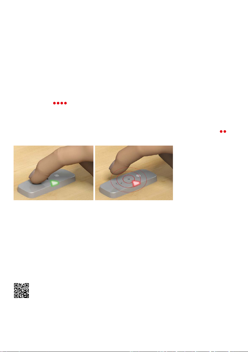
ANSWER 1: Pressing the Stove Alarm button during the
pre-alarm lowers the sensitivity slightly.
Other causes of alarms during normal cooking:
• A pot is removed from a hot burner
• A kettle/pot does not cover the burner
• Cooking without a lid
• A hot frying pan placed on the burner
ANSWER 2: If measures to prevent unnecessary alarms
have been performed a few times and the Stove
Alarm still emits alarms in the same situation, the
sensitivity should be adjusted less sensitive manually,
for example from level 4 to level 5. See page 18.
2. During the function test, the Stove Alarm does
not emit a sound when the button is pressed.
ANSWER: Make sure that the battery has power and
is inserted properly, "plus-side" up.
3. The Stove Alarm did not give an alarm in a
dangerous situation.
ANSWER 1: It is possible that the temperature was
not high enough to be identied as a dangerous
situation. The Stove Alarm takes dierent cooking
situations into account, including high-temperature
cooking, and should not give an alarm too easily.
Therefore, it only emits an alarm when a certain
temperature (or rate of temperature rise) is detected,
but still long before a real risk situation. However, it
is important to check the Stove Alarm’s function (see
the next sections).
ANSWER 2: Make sure that the Stove Alarm is correctly
installed. See page 5 and after.
ANSWER 3: It is possible to change the sensitivity
of the Stove Alarm, so it reacts earlier. Increase the
sensitivity by one or two steps. See page 18.
4. I cancelled the pre-alarm by mistake, even
though the alarm was triggered by a dangerous
situation. Has the Stove Alarm become too insen-
sitive now?
ANSWER: Deactivating the pre-alarm changes the
sensitivity, but only to a small extent. This pre-alarm
can therefore be deactivated several times without
aecting the sensitivity of the high temperature
alarm.
5. The Stove Alarm gives an alarm when I make
coee with an espresso pot.
Espresso pots are often much smaller than the burn-
er, and the heat from the burner makes the Stove
Alarm think there is a dangerous situation.
Use suitable size cooking vessels.
ANSWER: Deactivate the alarm by pressing the
Stove Alarm button. The sensitivity level of the Stove
Alarm will not change, as the espresso maker trig-
gered an alarm for maximum temperature and not
self-learning.
6. What do I do if the Stove Alarm must be re-
placed with a new one?
ANSWER: Contact the retailer for a new part.
7. Where can I nd the Stove Alarm model num-
ber?
ANSWER: On the underside of the Stove Alarm there
is a sticker with the model number.
FREQUENTLY ASKED
QUESTIONS
Change the sensitivity level
Due to dierences in kitchen environments, the sensitivity level of the
Stove Alarm may have to be set manually.
1. Remove the Stove Alarm from the installation plate
It makes 4 “beeps”( ).
2. Adjust the sensitivity level
See pages 4–7 for sensivitity levels to be applied.
Place the Stove Alarm on the table (as shown in the picture). Press and hold in the button until 2 “beeps”( )
are heard. Release the hold. The correct sensitivity can now be applied.
Note: When selecting the correct sensitivity level it is important the process is not rushed. Ensure the sensor
button is pressed rmly down each time, holding for a period of 1 second before releasing.
Ensure to pause for 1 second between each press.
3. Conrmation of setting
After 5–15 seconds, the Stove Alarm will conrm the sensitivity setting with the same number of “beeps”.
In case of error, start from step 2 again. Please note that the sensitivity level is conrmed by the appropriate
number of "beeps" only and not the LED ashes.
4. Activate the Stove Alarm
Return the Stove Alarm correctly onto the installation plate. Press the button once.
USER GUIDE
SETTINGS
“BEEP” .... “BEEP”
10
Watch the movie:
https://vimeo.com/321503955
Setting sensitivity