manuals.online logo
Brands
  1. Home
  2. •
  3. Brands
  4. •
  5. Black Box
  6. •
  7. Controllers
  8. •
  9. Black Box LES1204A-3G-R2 User manual

Black Box LES1204A-3G-R2 User manual

Remote Console Manager with GSM Modem QS Guide
Quick Start Guide
This Quick Start Guide helps you through installation, configuration,
and local operation. For more details, refer to the user manual.
LES1204A-3G-R2
Remote Console Manager (LES1204A-3G-R2) Quick Start Guide
2
Trademarks Used in this Manual
Black Box and the Double Diamond logo are registered trademarks of
BB Technologies, Inc.
Cisco is a registered trademark of Cisco Technology, Inc.
Linux is a registered trademark of Linus Torvalds.
Nagios is a registered trademark of Nagios Enterprises.
Any other trademarks mentioned in this manual are acknowledged to be the
property of the trademark owners.
Remote Console Manager (LES1204A-3G-R2) Quick Start Guide
3
Follow the steps listed below to get started:
Step 1: Check kit contents.
LES1204A-3G-R2 Remote Console Manager
This printed quick start guide
(2) UTP cables
(1) DB9F-RJ-45 adapter straight-pinned
(1) DB9F-RJ-45 adapter crossover-pinned
(1) RF antenna with bracket mount and 1-ft. (30-cm) cable
Universal input 12-VDC power pack
NOTE: To download the user manual, visit the Black Box Web site and enter
LES1204A-3G-R2 in the search bar.
Step 2: Connect the hardware.
NOTE: The LES1204A-3G-R2 Remote Console Manager has an internal 3G
GSM cellular modem. Your carrier will provide you with a SIM card to
activate your GSM cellular modem plan. The SIM card must be installed in
the Remote Console Manager before applying power.
Unscrew the SIM card access panel on the side of the Remote Console
Manager and insert the SIM card with contacts facing upward. The SIM
card will lock into place. You may use the tip of the RF antenna to fully
seat the SIM card. Replace the SIM card access panel.
Attach the RF antenna using the cable to the Remote Console Manager.
Connect your serial devices to the four SERIAL ports. The RJ-45 serial
connectors have Cisco® serial pinouts:
PIN
SIGNAL
DEFINITION
1
CTS
Clear To Send
2
DSR
Data Set Ready
3
RXD
Receive Data
4
GND
Signal Ground
5
GND
Signal Ground
6
TXD
Transmit Data
7
DTR
Data Terminal Ready
8
RTS
Request To Send
Figure 1. Cisco serial pinouts.
Connect the LAN port to your network.
Remote Console Manager (LES1204A-3G-R2) Quick Start Guide
4
Plug the power pack into the AC power receptacle and connect the DC
power cable to the Remote Console Manager’s
9-12 VDC power socket.
NOTE: On applying power, the “SIM” LED on top of the Remote Console
Manager will go on solid, indicating that the SIM has been inserted and
detected.
Step 3: Set up the Remote Console Manager.
The default Remote Console Manager IP address is 192.168.0.1 (subnet
mask 255.255.255.0). With a Web browser on any computer that is
connected through the LAN to the serial device server:
• Enter https://192.168.0.1 into the address bar.
NOTE: The LAN-connected computer must have an IP address in the same
network range (192.168.0.xxx) as the Remote Console Manager. If this is not
convenient, you can use the ARP Ping command to set the IP address (refer
to the user manual for details). The Remote Console Manager also has its
DHCP client enabled by default, so it will automatically accept any network
IP address assigned by any DHCP server on your network—and will then
respond at both 192.168.0.1 and its DHCP address.
Log in using the default system user name: root, and the default
password: default. A Welcome screen listing the basic configuration steps
is displayed.
Select “Change the default administration password on the Users page,”
enter and confirm a new password for root, and click “Apply.”
Remote Console Manager (LES1204A-3G-R2) Quick Start Guide
5
Figure 2. Serial & Network: User & Groups screen.
To assign your Remote Console Manager a static IP address or to
permanently enable DHCP, select “System: IP” then “Network Interface”
and check “DHCP” or “Static” for configuration method.
By default, only HTTPS and SSH access is enabled to the Remote
Console Manager itself. Use Service Access menu on System: Services
to change this, and to change access privileges for connected serial and
network devices.
Figure 3. System: Services screen.
Remote Console Manager (LES1204A-3G-R2) Quick Start Guide
6
Step 4: Configure serial and network devices.
Select “Serial & Network: Serial Port,” which will display the label, mode,
and protocol options currently set for the serial port. By default, all the
serial ports, except Port 1, are set to console server mode (see the user‘s
manual for other modes).
Figure 4. Serial & Network: Serial Port screen.
To configure a serial port, click “Edit.”
Configure the common settings (baud rate, parity, data bits, stop bits, and
flow control) to match those of the serial device being controlled.
Select the console server protocols (Telnet, SSH, TCP, and RFC2217)
that will be used for the data connection to the serial port.
NOTE: Port 1 is configured by default in Local Console (modem) mode. Use
the crossover-pinned DB9F-RJ-45 adapter and UTP cable to connect to a
terminal emulator application on your PC’s serial COM port. If you plan to
use out-of-band (OoB) dial-in access, connect this serial port to an external
modem as covered in detail in the user manual.
Click “Apply.”
To enable access through the Remote Console Manager to a locally
networked computer (referred to as a host), select “Serial & Network:
Network Hosts” and click “Add Host.”
Remote Console Manager (LES1204A-3G-R2) Quick Start Guide
7
Figure 5. Serial & Network: Network Hosts screen.
Enter the IP address/DNS name of the host.
Edit the permitted services used for accessing this host, for example,
HTTPS (TCP port 443), VNC (TCP port 5900), or add custom TCP or
UDP port numbers—only the services specified here are tunneled
through to the host. All other services are blocked.
Specify the level of information to be logged and monitored for each host
access.
Click “Apply.”
Step 5: Add new users.
NOTE: We recommend that you set up a new Administrator user (in the
admin group with full access privileges) and log in as this new user for all
ongoing administration functions (rather than continuing as root).
For each new user, select “Serial & Network: Users & Groups” and click
“Add User.”
Enter a username and enter and confirm a password.
Select one or multiple group memberships for the user. To grant limited
access to the management console, check the “users” group. To grant
full access to the management console, check the “admin” group. By
default, the user is granted no management console access.
Nominate the dial-in options for the user and the accessible hosts and
accessible ports the user is allowed to access.
Click “Apply.”
Remote Console Manager (LES1204A-3G-R2) Quick Start Guide
8
Figure 6. Serial & Network: Users & Groups screen.
NOTE: The Remote Console Manager comes with a default certificate for
initial configuration purposes only. You will need to direct your browser to
(temporarily) proceed and accept this untrusted certificate. It is
recommended as soon as possible thereafter you generate and install a new
trusted certificate. To produce the unique CSR and later upload the newly
issued certificate, select System: SSL Certificates.
Step 6: Establish connection to the cellular carrier.
Figure 7. System: Dial screen.
Remote Console Manager (LES1204A-3G-R2) Quick Start Guide
9
Select “Internal Cellular Modem”on the “System: Dial”menu and check
“Enable Dial-Out.”
Enter the carrier’s APN e.g. for AT&T (USA) simply enter “i2gold”, for
T-Mobile (USA) enter “epc.tmobile.com”, for InterNode (Aust) enter
“internode”and for Telstra (Aust) enter “telstra.internet.”
NOTE: Your GSM cellular carrier may have provided you with connection
details. However, you generally will only need to enter your provider’s APN
and leave the other fields blank. If provided a Pin Code you may need to use
it to unlock the SIM card.
NOTE: You may also need to use alternate DNS servers from those provided
by your carrier. To enable, check Enable Override DNS, then check the
Override returned DNS Servers box and enter the IP of the DNS servers into
the spaces provided.
Check “Apply”and a radio connection will be established with your
cellular carrier. Out-of-band access is enabled, so the cellular modem
connection is always ON.
Select “Status: Statistics” and verify the Connection Status in the
“Failover& Out-of-Band” page is shown as Connected. You can also
check your allocated IP address.
Measure the received signal strength RSSI from the “Cellular Statistics”
page.
Figure 8. Status: Statistics screen.
NOTE: An RSSI of -99 dbm to –90 dbm is Weak Coverage, -89 dbm to –70
dbm is Medium, and -69 dbm or greater is Strong
Remote Console Manager (LES1204A-3G-R2) Quick Start Guide
10
Step 7: Out of band access.
To directly access the Remote Console Manager, it needs to have a Public
IP address and it must not have SSH access firewalled. Almost all carriers
and cellular service providers offer corporate mobile data service/plans with
a Public (static or dynamic) IP address. These plans often have a service fee
attached.
If you have a static public IP address plan, you can directly access the
Remote Console Manager using the public IP Address provided by the
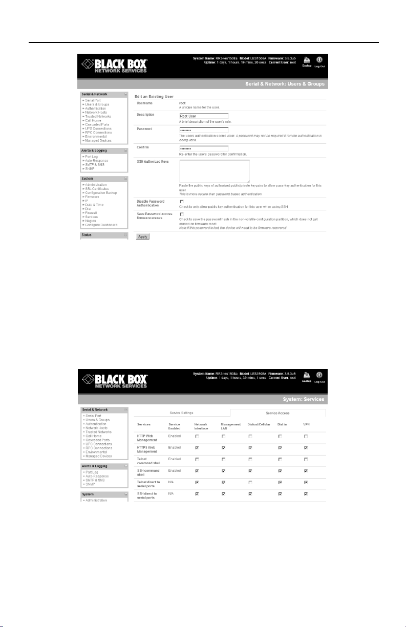
carrier. However, by default, only HTTPS and SSH access is enabled on
the OOB connection. So, you can browse to the Remote Console
Manager, but you cannot ping it.
If you have a dynamic Public IP address plan, then a DDNS service will
need to be configured (see the user’s manual for details). Once this is
done, you can then access the Remote Console Manager using the
allocated domain name.
NOTE: By default, most providers offer a consumer grade service that
provides dynamic Private IP address assignments to 3G devices. This
Private IP address is not visible across the Internet, but generally it is
adequate for home and general business use. If you have such a plan, the
Failover & Out-of-Band tab on the Status: Statistics page, will show your
carrier allocated a Private IP Address (in the range 10.0.x.x, 172.16.x.x or
192.168.x.x). For an inbound OOB connection with such a plan, you will
need to set up a VPN (see the user‘s manual for details).
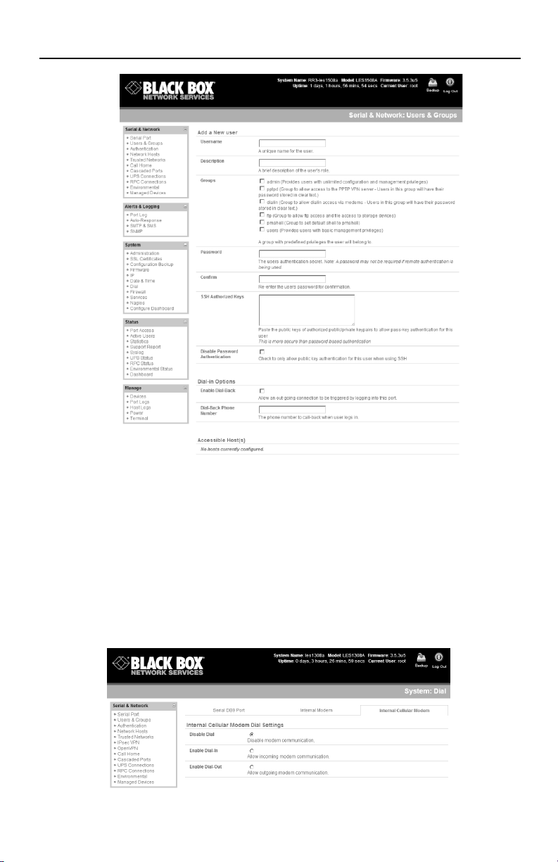
NOTE: In out-of-band access mode, the internal cellular modem will
continually stay connected. The alternative is to set up Failover mode. This
will tell the internal cellular connection to remain idle in a low power state. If
the primary and secondary probe addresses are not available, it will bring up
the cellular connection and connect back to the cellular carrier (see the
user’s manual for details).
Step 8: Advanced configurations.
The Remote Console Manager offers many more advanced functions
including:
The Alerts & Logging: Auto Response facility monitors serial ports, hosts,
user logins, UPSs (uninterruptible power supplies), and RPCs (remote
power controllers such as PDUs and IPMI devices). A broad selection of
trigger events (such as data patterns, temperature, or battery levels) can
Remote Console Manager (LES1204A-3G-R2) Quick Start Guide
11
be specified. When triggered, a warning e-mail, SMS, Nagios®, or SNMP
alert can be sent to a nominated destination or a user defined local
response sequence can be initiated (such as power cycling a device).
Extensive management of UPSs and RPCs using Open Source NUT and
Powerman tools. The “Manage: Power” facility enables both
administrators and regular users to monitor and control attached PDU
power strips, and servers with embedded IPMI BMCs.
Historical logs of all communications with serial and network-attached
devices, system activity, UPS and PDU power status, environmental
status, etc. The level of logging is set as ports and devices are
configured. Alerts & Logging: Port Log allows this history to be saved
locally or remotely. Logs can be viewed from the Status and Manage
menus.
Other advanced features, such as serial port cascading, remote
authentication, trusted networks, secure tunneling, Nagios distributed
monitoring, and the command line interface are covered in detail in the
user manual.
To download the user manual from the Web site:
1. Go to www.blackbox.com
2. Enter the product code (LES1204A-3G-R2) in the search box:
3. Click on the “Resources” tab on the product page, and select the
document you wish to download.
LES1204A-3G-R2 QSG, rev. 6

Other Black Box Controllers manuals

Black Box BOXILLA BXAMGR User manual

Black Box

Black Box BOXILLA BXAMGR User manual

Black Box EVEMS240-100-3R User manual

Black Box

Black Box EVEMS240-100-3R User manual

Black Box 3174/3274 I-Mux Series User manual

Black Box

Black Box 3174/3274 I-Mux Series User manual

Black Box QuikConnect ME0007A-HDSL User manual

Black Box

Black Box QuikConnect ME0007A-HDSL User manual

Black Box SW544A-M User manual

Black Box

Black Box SW544A-M User manual

Black Box iPATH ACR1000A-CTL-24 User manual

Black Box

Black Box iPATH ACR1000A-CTL-24 User manual

Black Box MCX-G2-CONTROL-24 User manual

Black Box

Black Box MCX-G2-CONTROL-24 User manual

Black Box VSW-MC-CTRL MediaCento IPX Controller User manual

Black Box

Black Box VSW-MC-CTRL MediaCento IPX Controller User manual

Black Box VSC-VPLEX4 User manual

Black Box

Black Box VSC-VPLEX4 User manual

Black Box servswitch DTX5000-CTL User manual

Black Box

Black Box servswitch DTX5000-CTL User manual

Black Box iPATH ACR1000A-CTL-24 User manual

Black Box

Black Box iPATH ACR1000A-CTL-24 User manual

Black Box MEDIACENTO VSW-MC-CTRL User manual

Black Box

Black Box MEDIACENTO VSW-MC-CTRL User manual

Popular Controllers manuals by other brands

Neles B1C K installtion, maintenance and operating instructions

Neles

Neles B1C K installtion, maintenance and operating instructions

SODECA EC CONTROL user manual

SODECA

SODECA EC CONTROL user manual

Vetus SENSORD Operation manual and installation instructions

Vetus

Vetus SENSORD Operation manual and installation instructions

Altronix Maximal3V installation guide

Altronix

Altronix Maximal3V installation guide

Licht-Technik Mix4-6 Functional description

Licht-Technik

Licht-Technik Mix4-6 Functional description

Daruifuno MCC200 user manual

Daruifuno

Daruifuno MCC200 user manual

sauter EQJW145 operating manual

sauter

sauter EQJW145 operating manual

TLV SC-F71 instruction manual

TLV

TLV SC-F71 instruction manual

CEM Systems Controller webEntry II specification

CEM Systems

CEM Systems Controller webEntry II specification

NDE Pool DDPHCL2 instruction manual

NDE Pool

NDE Pool DDPHCL2 instruction manual

Sielox AC-1500 Series installation manual

Sielox

Sielox AC-1500 Series installation manual

Telecrane F25-60 operating instructions

Telecrane

Telecrane F25-60 operating instructions

Emerson NELSON CM-2201 Installation and operating instructions

Emerson

Emerson NELSON CM-2201 Installation and operating instructions

Alinco EJ-50U instruction manual

Alinco

Alinco EJ-50U instruction manual

LOVATO ELECTRIC RGK600 installation manual

LOVATO ELECTRIC

LOVATO ELECTRIC RGK600 installation manual

SMC Networks ZL3 Series Original instructions

SMC Networks

SMC Networks ZL3 Series Original instructions

Allen-Bradley PLC-3 Series quick start

Allen-Bradley

Allen-Bradley PLC-3 Series quick start

Balboa Water Group Cal Spas CS5100DV Tech sheet

Balboa Water Group

Balboa Water Group Cal Spas CS5100DV Tech sheet

manuals.online logo
manuals.online logoBrands
  • About & Mission
  • Contact us
  • Privacy Policy
  • Terms and Conditions

Copyright 2025 Manuals.Online. All Rights Reserved.