e2v ELIIXA+ 8k/4k CL User manual

ELIIXA+ 8k/4k CL
Cmos Multi-Line Color Camera
User Manual

ELIIXA+®
8k/4k CL Color
2e2v semiconductors SAS 2014
Summary
1
CAMERA OVERVIEW .................................................................................4
1.1 Features ....................................................................................................................................................... 4
1.2 Key Specifications....................................................................................................................................... 4
1.3 Description .................................................................................................................................................. 5
1.4 Typical Applications.................................................................................................................................... 5
2
CAMERA PERFORMANCES............................................................................6
2.1 Camera Characterization ............................................................................................................................ 6
2.2 Image Sensor and color modes.................................................................................................................. 7
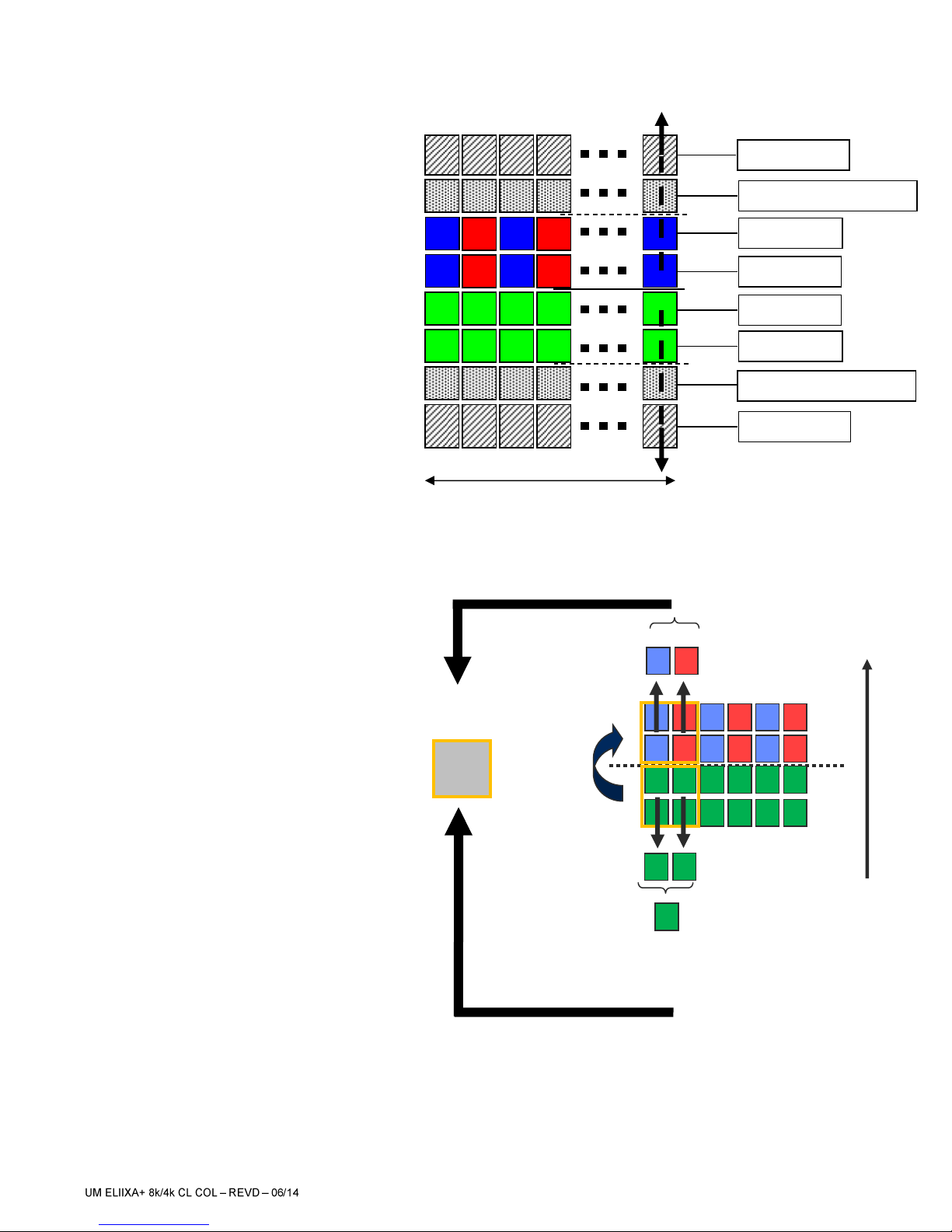
2.2.1 True Colour Enhanced Mode (TCE) .........................................................................................................................................7
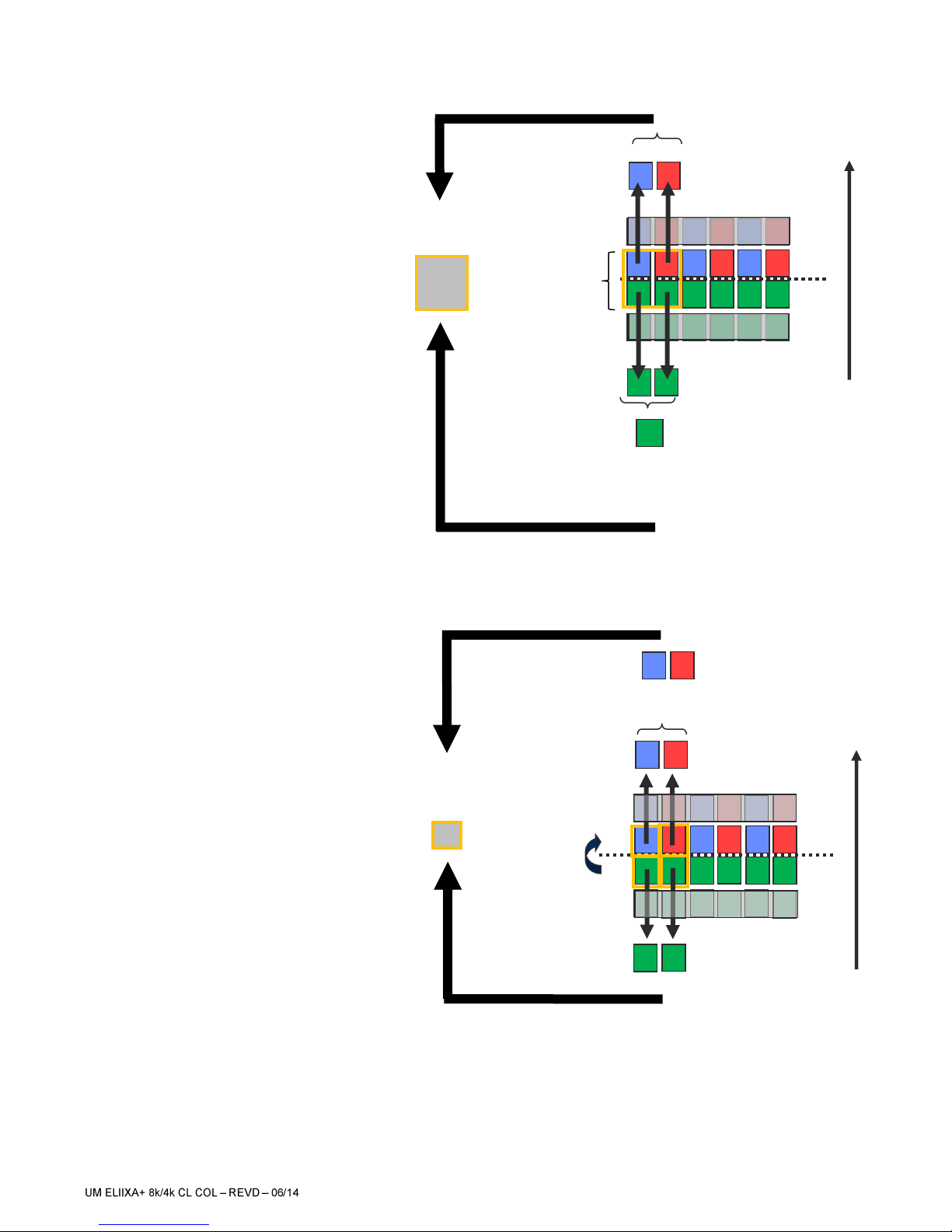
2.2.2 True Colour Single Mode (TCS) ...............................................................................................................................................8
2.2.3 Full Definition Single Mode (FDS)...........................................................................................................................................8
2.2.4 Full Definition Enhanced Mode (FDE).....................................................................................................................................9
2.3 Response & QE curves.............................................................................................................................. 10
2.3.1 Quantum Efficiency ............................................................................................................................................................... 10
2.3.2 Spectral Response................................................................................................................................................................. 10
3
CAMERA HARDWARE INTERFACE ................................................................... 11
3.1 Mechanical Drawings................................................................................................................................ 11
3.2 Input/output Connectors and LED ........................................................................................................... 12
3.2.1 Power Connector ................................................................................................................................................................... 13
3.2.2 Status LED Behaviour............................................................................................................................................................ 14
3.2.3 CameraLink Output Configuration........................................................................................................................................ 14
3.2.3.1
True Color (Single or Enhanced)
........................................................................................................................... 15
3.2.3.2
Full Definition (Single or Enhanced)
..................................................................................................................... 16
4
STANDARD CONFORMITY .......................................................................... 19
4.1 CE Conformity ............................................................................................................................................ 19
4.2 FCC Conformity .......................................................................................................................................... 19
4.3 RoHs Conformity........................................................................................................................................ 19
5
GETTING STARTED ................................................................................. 21
5.1 Out of the box............................................................................................................................................ 21
5.2 Setting up in the system........................................................................................................................... 21
6
CAMERA SOFTWARE INTERFACE .................................................................... 22
6.1 Control and Interface ................................................................................................................................ 22
6.2 Serial Protocol and Command Format..................................................................................................... 23
6.2.1 Syntax ................................................................................................................................................................................... 23
6.2.2 Command Processing .......................................................................................................................................................... 23
6.2.3 GenICam ready ..................................................................................................................................................................... 23
6.3 Camera Commands................................................................................................................................... 24
6.3.1 Information ........................................................................................................................................................................... 24
6.3.2 Image Format ........................................................................................................................................................................ 26
6.3.3 Acquisition Control............................................................................................................................................................... 30
6.3.4 Gain and Offset...................................................................................................................................................................... 31
6.3.4.1 White Balance ...................................................................................................................................................... 32
6.3.5 Flat Field Correction.............................................................................................................................................................. 34
6.3.5.1 Activation.............................................................................................................................................................. 36

ELIIXA+®
8k/4k CL Color
3e2v semiconductors SAS 2014
6.3.5.2 Automatic Calibration .......................................................................................................................................... 36
6.3.5.3 Manual Flat Field Correction................................................................................................................................ 37
6.3.5.4 FFC User Bank Management................................................................................................................................ 38
6.3.6 Statistics and Line Profile .................................................................................................................................................... 39
6.3.7 Privilege Level........................................................................................................................................................................ 41
6.3.8 Save & Restore Settings........................................................................................................................................................ 41
7
APPENDIX A: Test Patterns......................................................................... 42
7.1 Test Pattern 1: Vertical wave..................................................................................................................... 42
7.2 Test Pattern 2: Fixed Horizontal Ramps................................................................................................... 42
8
APPENDIX B: Timing Diagrams ..................................................................... 43
8.1 Synchronization Modes with Variable Exposure Time ........................................................................... 43
8.2 Synchronisation Modes with Maximum Exposure Time ........................................................................ 44
8.3 Timing Values ............................................................................................................................................ 44
9
APPENDIX C: CameraLink Data Cables.............................................................. 45
9.1 Choosing the Cable................................................................................................................................... 45
9.2 Choosing the Data Rate ............................................................................................................................ 46
10
APPENDIX D: Lens Mounts ...................................................................... 47
10.1 F-Mount...................................................................................................................................................... 47
10.2 T2 & M42x1 Mounts............................................................................................................................... 48
11
APPENDIX E: Troubleshooting...................................................................... 49
11.1 Camera....................................................................................................................................................... 49
11.2 CommCam Connection ............................................................................................................................. 49
12
APPENDIX F: Commands ........................................................................ 50
12.1 Device Control ........................................................................................................................................... 50
12.2 Image Format ......................................................................................................................................... 50
12.3 Synchro and Acquisition....................................................................................................................... 51
12.4 Gain & Offset.......................................................................................................................................... 51
12.5 Flat Field Correction .................................................................................................................................. 52
12.6 Save and Restore................................................................................................................................... 52
12.7 Camera Status ........................................................................................................................................... 53
12.8 Communication ..................................................................................................................................... 53
12.9 Line Profile Average............................................................................................................................... 53
13
APPENDIX G: Revision History ................................................................... 55

ELIIXA+®
8k/4k CL Color
4e2v semiconductors SAS 2014
1CAMERA OVERVIEW
1.1
Features
Cmos Colour Sensor :
o8192 RGB Pixels, 5 x 5µm (Full Definition)
o4096 RGB Pixels 10x10µm (True Colour)
Interface : CameraLink® (up to 10 Taps at 85MHz)
Line Rate :
oUp to 50000 l/s In 8k Full Definition Mode
oUp to 66000 l/s in 4k True Colour Mode
Bit Depth : 24bits (RGB 8bits)
Scan Direction
Flat Field Correction
Low Power Consumption : <9W
F-Mount compliance
1.2
Key Specifications
Characteristics
Typical Value
Unit
Sensor Characteristics at Maximum Pixel Rate
Resolution
8192 or 4096
RGB Pixels
pixel size (square)
5 or 10
µm
Max line rate
4096 RGB Pixels True Color Mode
66
kHz
8192 RGB Pixels Full Definition Modes
50
kHz
Radiometric Performance at Maximum Pixel Rate and minimum camera gain
Bit depth
3 x 8
Bits
Response (Peak) : True Color or Full Def Enhanced
Red
11.8
LSB 8bits/(nJ/cm²)
Green
11.2
LSB 8bits/(nJ/cm²)
Blue
7.8
LSB 8bits/(nJ/cm²)
Response non linearity
< 1
%
PRNU HF Max
3
%
Dynamic range
65
dB

ELIIXA+®
8k/4k CL Color
5e2v semiconductors SAS 2014
1.3
Description
e2v’s next generation of line scan cameras are setting new, high standards for line rate and image quality. Thanks to
e2v’s recently developed multi-line CMOS technology, the camera provides an unmatched 100,000 lines/s and
combines high response with an extremely low noise level; this delivers high signal to noise ratio even when short
integration times are required or when illumination is limited. The 5μm pixel size is arranged in four active lines and
dual line filter configuration allowing the camera to be operated in several modes: True colour mode with 10μm RGB
pixels to provide equivalent colour fidelity to 10μm pixel tri-linear solutions with advanced immunity to web variation
or Full definition mode with a 8192 RGB pixel resolution.
1.4
Typical Applications
Raw material surface inspection
Flat panel display inspection
PCB inspection
Solar cell inspection
Parcel and postal sorting
High resolution document scanning
Print and paper inspection
Functionality (Programmable via GenICam Control Interface)
Analog Gain
Up to 12 (x4)
dB
Offset
-4096 to +4096
LSB
Trigger Mode
Timed (Free run) and triggered (Ext Trig, Ext ITC) modes
SensorModes
True Color Enhanced : 4096 RGB Pixels of 10x10µm
True Color Single : 4096 RGB Pixels of 10x10µm
Full Definition Enhanced : 8192 RGB Pixels 5x5µm
Full Definition Single : 8192 RGB Pixels 5x5µm
Mechanical and Electrical Interface
Size (w x h x l)
126 x 60 x 35
mm
Weight
360
g
Lens Mounts
F,T2,M42
-
Sensor alignment ( see chapter 4 )
±100
µm
Sensor flatness
±35
µm
Power supply
12 - 24
V
Power dissipation –Typ. while grabbing
< 9
W
General Features
Operating temperature
0 to 55 (front face) or 70 (Internal)
°C
Storage temperature
-40 to 70
°C
Regulatory
CE, FCC and RoHS compliant

ELIIXA+®
8k/4k CL Color
6e2v semiconductors SAS 2014
2CAMERA PERFORMANCES
2.1
Camera Characterization
Unit
True Color (8k)
Full Definition Single
Full Definition Enhanced
Typ.
Max
Typ.
Max
Typ.
Max
Dark Noise RMS
LSB
0.12
1.2
0.11
1.2
0.12
1.2
Dynamic Range
-
2125:1
-
2125:1
-
2125:1
-
RMS Noise (3/4 Sat)
LSB
2.2
-
2.15
4
2.2
4
Full Well Capacity
e-
(per color)
13650
-
13650
-
13650
-
SNR (3/4 Sat)
dB
40
-
40
-
40
-
Peak Response
(460/530/660nm)
LSB 8bits/
(nJ/cm2)
8/10/12
-
4/5/6
-
8/10/12
-
Non Linearity
%
0,3
-
0,3
-
0,3
-
Without Flat Field Correction :
FPN rms
LSB
0.21
1
0.23
1
0.22
1
FPN pk-pk
LSB
1
2
1
2
1
2
PRNU hf (3/4 Sat)
%
0.13
0,35
0.123
0,35
0.14
0,35
PRNU pk-pk (3/4 Sat)
%
1.1
3
1
3
1.25
3
Test conditions :
All values are given at Nominal Gain (0dB) : Preamp Gain x1, Amp Gain 0dB
Figures in LSB are for a 8bits format
Measured at exposure time = 400µs and line period = 400µs in Ext Trig Mode (Max Exposure Time)
Maximum data rate

ELIIXA+®
8k/4k CL Color
7e2v semiconductors SAS 2014
2.2
Image Sensor and color modes
The Eliixa+ Colour 8k sensor is composed of
two pairs of sensitive lines.
The Colour version has been completed with
RGB colour Filter and disposed as detailed
beside.
Each pair of lines use the same Analog to
Digital Column converter (ADC Column). An
appropriate (embedded) Time delay in the
exposure between each line this allows to
combine two successive exposures in order to
double the sensitivity of a single line.
This Time Delay Exposure is used only in the
Full Definition Enhanced mode (See Below).
2.2.1 True Colour Enhanced Mode (TCE)
10µm pixels (R,G,B)
Twice less pixels than B/W
Requires x3/2 the data flow of B&W
High Sensitivity True Color mode:
Equivalent to 6 x Pixels of 5µm (with
their respective colour filters).
“Full Exposure control” not needed in
TC as the TDI is not active (only
binning). The Exposure time can be
control as for a single line mode.
8192 Pixels
ADC Column
ADC Column
Intermediate Blind Pixel
Pixel Line A
Pixel Line B
Pixel Line C
Pixel Line D
Intermediate Blind Pixel
Web
Direction
Delay : 1 line
of 10µm
Double Green :
Vertical Binning
Double Red :
Vertical Binning
Double Blue :
Vertical Binning
Pixel 10µm
{RGB}
Double Green :
Vertical Binning
Green Pixels
averaging

ELIIXA+®
8k/4k CL Color
8e2v semiconductors SAS 2014
2.2.2 True Colour Single Mode (TCS)
10µm pixels (R,G,B)
Twice less pixels than B/W
Requires x3/2 the data flow of B&W
Sensitivity Half of the TCE mode:
Equivalent to 6 x Pixels of 5µm (with
their respective colour filters).
“Full Exposure control” not needed in
TC as the TDI is not active (only
binning). The Exposure time can be
control as for a single line mode.
Not sensitive to the Scanning direction
and the variation of the aspect ratio of
the image.
2.2.3 Full Definition Single Mode (FDS)
5µm pixels (R,G,B)
Same definition than B&W
Requires x3 the data flow of the B&W
Sensitivity is half of the TC mode
available : Equivalent to 3 x Pixels of
5µm (with their respective colour
filters).
“Full Exposure control” not needed in
this mode as the Time Delay Exposure
is not active. The Exposure time can be
control as for a single line mode.
Single Red
Single Blue
Pixel 10µm
{RGB}
One Pixel 10x10µm
grabbed
In the same time
Simple Green
Double Green
Web
Direction
Delay : 1 line
of 5µm
Single Green
Single Red
Single Blue
Blue or Red
Interpolated(*)
Pixel 5µm
{RGB}
Single Green
Web
Direction

ELIIXA+®
8k/4k CL Color
9e2v semiconductors SAS 2014
2.2.4 Full Definition Enhanced Mode (FDE)
5µm pixels (R,G,B)
Same definition than B&W
Requires x3 the data flow of the B&W
Sensitivity is the same as the TC mode
available : Equivalent to 6 x Pixels of
5µm (with their respective colour
filters).
“Full Exposure control” is activated in
this mode as the Time Delay Exposure
is active.
Delay : 1 line
of 5µm
Double Green
TDE
Double Green
TDE
Double Red
TDE
Double Blue
TDE
Blue or Red
Interpolated(*)
Pixel 5µm
{RGB}
Web
Direction

ELIIXA+®
8k/4k CL Color
10 e2v semiconductors SAS 2014
2.3
Response & QE curves
2.3.1 Quantum Efficiency
2.3.2 Spectral Response
This Response is for a single 5x5µm pixel of each color (True Color Single or Full Definition Single modes).

ELIIXA+®
8k/4k CL Color
11 e2v semiconductors SAS 2014
3CAMERA HARDWARE INTERFACE
3.1
Mechanical Drawings
The Step file is available on
the web :
www.e2v.com/cameras
X
Y
Z

ELIIXA+®
8k/4k CL Color
12 e2v semiconductors SAS 2014
3.2
Input/output Connectors and LED
Sensor alignment
Z = -10.3 mm
±100µm
X = 9.5 mm
±100 µm
Y = 62.5mm
±100 µm
Flatness
50 µm
Rotation (X,Y plan)
±0,15°
Tilt (versus lens mounting plane)
50µm
USB Connector
For Firmware
upgrade
Power Connector :
12-24V DC
Multi-Colored
LED for Status
and diagnostic
CameraLink
Connector CL1
CameraLink
Connector CL2

ELIIXA+®
8k/4k CL Color
13 e2v semiconductors SAS 2014
3.2.1 Power Connector
Camera connector type: Hirose HR10A-7R-6PB (male)
Cable connector type: Hirose HR10A-7P-6S (female)
Camera side description
Signal
Pin
Signal
Pin
PWR
1
GND
4
PWR
2
GND
5
PWR
3
GND
6
Power supply from 12 to 24v
Power 7,5W max with an typical inrush current peak of
1A
during power up
Typical current/Power during the grab (possible variation : +/- 5%)
Power Time : Max 40s (Green Light)
Inrush Current Peak Current Establishment time and level
24V
12V
Camera supply
(Line Period Minimum)
Supply 12V
Supply 24V
I(mA)
P(W)
I(mA)
P(W)
Full 8Taps
605
7.26
303
7.272
Deca 10Taps
613
7.356
308
7.392
Base 3Taps RGB
589
7.068
298
7.152
Medium 2x 3Taps RGB
598
7.176
302
7.248

ELIIXA+®
8k/4k CL Color
14 e2v semiconductors SAS 2014
3.2.2 Status LED Behaviour
After less than 2 seconds of power establishment, the LED first lights up in ORANGE. Then after a Maximum of 40 seconds,
the LED must turn in a following colour :
Colour and state
Meaning
Green
and continuous
OK
Green
and blinking slowly
Waiting for Ext Trig (Trig1 and/or Trig2)
Red
and continuous
Camera out of order : Internal firmware error
3.2.3 CameraLink Output Configuration
Adjacent Channels
Base : 3 Channels RGB 8bits
3 x 85MHz
Medium : 2 x 3 Channels RGB 8bits
2x 3 x 85MHz
Full : 8 Channels 8bits
8 x 85MHz
Deca : 10 Channels 8bits
10 x 85MHz
Sensor Mode
True Color
4096 pixels Red 8bits
4096 pixels Average Green 8bits
4096 pixels Blue 8bits
Full Definition Single
4096 Pixels Greenred, 8bits
4096 Pixels Greenblue, 8bits
4096 Pixels Red, 8bits
4096 Pixels Blue, 8bits
Full Definition Enhanced
4096 Pixels Greenred, 8bits
4096 Pixels Greenblue, 8bits
4096 Pixels Red, 8bits
4096 Pixels Blue, 8bits
Output Configuration
Base 3 x 8bits
Dual Base 2x 3x8bits
Full 8 x 8bits
Raw mode : Number of pixels to
Output is optimized. Red and Blue
Are not interpolated.
Deca 10 x 8bits
Raw mode : Same as for Full 8 taps.
12288 Pixels
total
16384 Pixels
total
4096 Pixels RGB
total
8192 Pixels RGB
Pixels to be outputted
outputtedoutput

ELIIXA+®
8k/4k CL Color
15 e2v semiconductors SAS 2014
3.2.3.1
True Color (Single or Enhanced)
In Base Output Mode
Tap1
RED
RED
RED
RED
RED
RED
RED
RED
RED
RED
RED
RED
RED
RED
1
3
5
7
9
11
13
15
8181
8183
8185
8187
8189
8191
Tap2
GREEN
GREEN
GREEN
GREEN
GREEN
GREEN
GREEN
GREEN
GREEN
GREEN
GREEN
GREEN
GREEN
GREEN
1
2
3
4
5
6
7
8
4091
4092
4093
4094
4095
4096
Tap3
BLUE
BLUE
BLUE
BLUE
BLUE
BLUE
BLUE
BLUE
BLUE
BLUE
BLUE
BLUE
BLUE
BLUE
2
4
6
8
10
12
14
16
8182
8184
8186
8188
8190
8192
In Medium or Dual Base Output Mode
Connector 1
Tap1
RED
RED
RED
RED
RED
RED
RED
RED
RED
RED
RED
RED
RED
RED
1
2
3
4
5
6
7
8
2043
2044
2045
2046
2047
2048
Tap2
GREEN
GREEN
GREEN
GREEN
GREEN
GREEN
GREEN
GREEN
GREEN
GREEN
GREEN
GREEN
GREEN
GREEN
1
2
3
4
5
6
7
8
2043
2044
2045
2046
2047
2048
Tap3
BLUE
BLUE
BLUE
BLUE
BLUE
BLUE
BLUE
BLUE
BLUE
BLUE
BLUE
BLUE
BLUE
BLUE
1
2
3
4
5
6
7
8
2043
2044
2045
2046
2047
2048
Connector 2
Tap4
RED
RED
RED
RED
RED
RED
RED
RED
RED
RED
RED
RED
RED
RED
2049
2050
2051
2052
2053
2054
2055
2056
4091
4092
4093
4094
4095
4096
Tap5
GREEN
GREEN
GREEN
GREEN
GREEN
GREEN
GREEN
GREEN
GREEN
GREEN
GREEN
GREEN
GREEN
GREEN
2049
2050
2051
2052
2053
2054
2055
2056
4091
4092
4093
4094
4095
4096
Tap6
BLUE
BLUE
BLUE
BLUE
BLUE
BLUE
BLUE
BLUE
BLUE
BLUE
BLUE
BLUE
BLUE
BLUE
2049
2050
2051
2052
2053
2054
2055
2056
4091
4092
4093
4094
4095
4096
In Full 8 Taps Output Mode
Connector 1
Tap1
RED
BLUE
GREEN
RED
BLUE
GREEN
RED
BLUE
RED
BLUE
GREEN
RED
BLUE
GREEN
1
3
6
9
11
14
17
19
4081
4083
4086
4089
4091
4094
Tap2
GREEN
RED
BLUE
GREEN
RED
BLUE
GREEN
RED
GREEN
RED
BLUE
GREEN
RED
BLUE
1
4
6
9
12
14
17
20
4081
4084
4086
4089
4092
4094
Tap3
BLUE
GREEN
RED
BLUE
GREEN
RED
BLUE
GREEN
BLUE
GREEN
RED
BLUE
GREEN
RED
1
4
7
9
12
15
17
20
4081
4084
4087
4089
4092
4095
Connector 2
Tap4
RED
BLUE
GREEN
RED
BLUE
GREEN
RED
BLUE
RED
BLUE
GREEN
RED
BLUE
GREEN
2
4
7
10
12
15
18
20
4082
4084
4087
4090
4092
4095
Tap5
GREEN
RED
BLUE
GREEN
RED
BLUE
GREEN
RED
GREEN
RED
BLUE
GREEN
RED
BLUE
2
5
7
10
13
15
18
21
4082
4085
4087
4090
4093
4095
Tap6
BLUE
GREEN
RED
BLUE
GREEN
RED
BLUE
GREEN
BLUE
GREEN
RED
BLUE
GREEN
RED
2
5
8
10
13
16
18
21
4082
4085
4088
4090
4093
4096
Tap7
RED
BLUE
GREEN
RED
BLUE
GREEN
RED
BLUE
RED
BLUE
GREEN
RED
BLUE
GREEN
3
5
8
11
13
16
19
21
4083
4085
4088
4091
4093
4096
Tap8
GREEN
RED
BLUE
GREEN
RED
BLUE
GREEN
RED
GREEN
RED
BLUE
GREEN
RED
BLUE
3
6
8
11
14
16
19
22
4083
4086
4088
4091
4094
4096

ELIIXA+®
8k/4k CL Color
16 e2v semiconductors SAS 2014
In Deca 10 Taps Output Mode
Connector 1
Tap1
RED
GREEN
BLUE
RED
GREEN
BLUE
RED
GREEN
BLUE
RED
GREEN
BLUE
RED
GREEN
1
4
7
11
14
17
21
24
4077
4081
4084
4087
4091
4094
Tap2
GREEN
BLUE
RED
GREEN
BLUE
RED
GREEN
BLUE
RED
GREEN
BLUE
RED
GREEN
BLUE
1
4
8
11
14
18
21
24
4078
4081
4084
4088
4091
4094
Tap3
BLUE
RED
GREEN
BLUE
RED
GREEN
BLUE
RED
GREEN
BLUE
RED
BLUE
BLUE
RED
1
5
8
11
15
18
21
25
4078
4081
4085
4088
4091
4095
Connector 2
Tap4
RED
GREEN
BLUE
RED
GREEN
BLUE
RED
GREEN
BLUE
RED
GREEN
BLUE
RED
GREEN
2
5
8
12
15
18
22
25
4078
4082
4085
4088
4092
4095
Tap5
GREEN
BLUE
RED
GREEN
BLUE
RED
GREEN
BLUE
RED
GREEN
BLUE
RED
GREEN
BLUE
2
5
9
12
15
19
22
25
4079
4082
4085
4089
4092
4095
Tap6
BLUE
RED
GREEN
BLUE
RED
GREEN
BLUE
RED
GREEN
BLUE
RED
GREEN
BLUE
RED
2
6
9
12
16
19
22
26
4079
4082
4086
4089
4092
4096
Tap7
RED
GREEN
BLUE
RED
GREEN
BLUE
RED
GREEN
BLUE
RED
GREEN
BLUE
RED
GREEN
3
6
9
13
16
19
23
26
4079
4083
4086
4089
4093
4096
Tap8
GREEN
BLUE
RED
GREEN
BLUE
RED
GREEN
BLUE
RED
GREEN
BLUE
RED
GREEN
BLUE
3
6
10
13
16
20
23
26
4080
4083
4086
4090
4093
4096
Tap9
BLUE
RED
GREEN
BLUE
RED
GREEN
BLUE
RED
GREEN
BLUE
RED
GREEN
BLUE
3
7
10
13
17
20
23
27
4080
4083
4087
4090
4093
Tap10
RED
GREEN
BLUE
RED
GREEN
BLUE
RED
GREEN
BLUE
RED
GREEN
BLUE
RED
4
7
10
14
17
20
24
27
4080
4084
4087
4090
4094
3.2.3.2
Full Definition (Single or Enhanced)
In Base Output Mode
Tap1
RED
RED
RED
RED
RED
RED
RED
RED
RED
RED
RED
RED
RED
RED
1
2
3
4
5
6
7
8
8187
8188
8189
8190
8191
8192
Tap2
GREEN
GREEN
GREEN
GREEN
GREEN
GREEN
GREEN
GREEN
GREEN
GREEN
GREEN
GREEN
GREEN
GREEN
1
2
3
4
5
6
7
8
8187
8188
8189
8190
8191
8192
Tap3
BLUE
BLUE
BLUE
BLUE
BLUE
BLUE
BLUE
BLUE
BLUE
BLUE
BLUE
BLUE
BLUE
BLUE
1
2
3
4
5
6
7
8
8187
8188
8189
8190
8191
8192

ELIIXA+®
8k/4k CL Color
17 e2v semiconductors SAS 2014
In Medium or Dual Base Output Mode
Connector 1
Connector 2
Tap4
RED
RED
RED
RED
RED
RED
RED
RED
RED
RED
RED
RED
RED
RED
4097
4098
4099
4100
4101
4102
4103
4104
8187
8188
8189
8190
8191
8192
Tap5
GREEN
GREEN
GREEN
GREEN
GREEN
GREEN
GREEN
GREEN
GREEN
GREEN
GREEN
GREEN
GREEN
GREEN
4097
4098
4099
4100
4101
4102
4103
4104
8187
8188
8189
8190
8191
8192
Tap6
BLUE
BLUE
BLUE
BLUE
BLUE
BLUE
BLUE
BLUE
BLUE
BLUE
BLUE
BLUE
BLUE
BLUE
4097
4098
4099
4100
4101
4102
4103
4104
8187
8188
8189
8190
8191
8192
In Full 8 Taps Output Mode
Connector 1
Tap1
BLUE
RED
BLUE
RED
BLUE
RED
BLUE
RED
BLUE
RED
BLUE
RED
BLUE
RED
1
2
3
4
5
6
7
8
2043
2044
2045
2046
2047
2048
Tap2
GREEN
GREEN
GREEN
GREEN
GREEN
GREEN
GREEN
GREEN
GREEN
GREEN
GREEN
GREEN
GREEN
GREEN
1
2
3
4
5
6
7
8
2043
2044
2045
2046
2047
2048
Tap3
BLUE
RED
BLUE
RED
BLUE
RED
BLUE
RED
BLUE
RED
BLUE
RED
BLUE
RED
2049
2050
2051
2052
2053
2054
2055
2056
4091
4092
4093
4094
4095
4096
Connector 2
Tap4
GREEN
GREEN
GREEN
GREEN
GREEN
GREEN
GREEN
GREEN
GREEN
GREEN
GREEN
GREEN
GREEN
GREEN
2049
2050
2051
2052
2053
2054
2055
2056
4091
4092
4093
4094
4095
4096
Tap5
BLUE
RED
BLUE
RED
BLUE
RED
BLUE
RED
BLUE
RED
BLUE
RED
BLUE
RED
4097
4098
4099
4100
4101
4102
4103
4104
6139
6140
6141
6142
6143
6144
Tap6
GREEN
GREEN
GREEN
GREEN
GREEN
GREEN
GREEN
GREEN
GREEN
GREEN
GREEN
GREEN
GREEN
GREEN
4097
4098
4099
4100
4101
4102
4103
4104
6139
6140
6141
6142
6143
6144
Tap7
BLUE
RED
BLUE
RED
BLUE
RED
BLUE
RED
BLUE
RED
BLUE
RED
BLUE
RED
6145
6146
6147
6148
6149
6150
6151
6152
8187
8188
8189
8190
8191
8192
Tap8
GREEN
GREEN
GREEN
GREEN
GREEN
GREEN
GREEN
GREEN
GREEN
GREEN
GREEN
GREEN
GREEN
GREEN
6145
6146
6147
6148
6149
6150
6151
6152
8187
8188
8189
8190
8191
8192
Tap1
RED
RED
RED
RED
RED
RED
RED
RED
RED
RED
RED
RED
RED
RED
1
2
3
4
5
6
7
8
4091
4092
4093
4094
4095
4096
Tap2
GREEN
GREEN
GREEN
GREEN
GREEN
GREEN
GREEN
GREEN
GREEN
GREEN
GREEN
GREEN
GREEN
GREEN
1
2
3
4
5
6
7
8
4091
4092
4093
4094
4095
4096
Tap3
BLUE
BLUE
BLUE
BLUE
BLUE
BLUE
BLUE
BLUE
BLUE
BLUE
BLUE
BLUE
BLUE
BLUE
1
2
3
4
5
6
7
8
4091
4092
4093
4094
4095
4096

ELIIXA+®
8k/4k CL Color
18 e2v semiconductors SAS 2014
In Deca 10 Taps Output Mode
Connector 1
Tap1
BLUE
RED
BLUE
RED
BLUE
RED
BLUE
RED
BLUE
RED
BLUE
RED
BLUE
RED
1
2
3
4
5
6
7
8
1633
1634
1635
1636
1637
1638
Tap2
GREEN
GREEN
GREEN
GREEN
GREEN
GREEN
GREEN
GREEN
GREEN
GREEN
GREEN
GREEN
GREEN
GREEN
1
2
3
4
5
6
7
8
1633
1634
1635
1636
1637
1638
Tap3
BLUE
RED
BLUE
RED
BLUE
RED
BLUE
RED
BLUE
RED
BLUE
RED
BLUE
RED
1639
1640
1641
1642
1643
1644
1645
1646
3271
3272
3273
3274
3275
3276
Connector 2
Tap4
GREEN
GREEN
GREEN
GREEN
GREEN
GREEN
GREEN
GREEN
GREEN
GREEN
GREEN
GREEN
GREEN
GREEN
1639
1640
1641
1642
1643
1644
1645
1646
3271
3272
3273
3274
3275
3276
Tap5
BLUE
RED
BLUE
RED
BLUE
RED
BLUE
RED
BLUE
RED
BLUE
RED
BLUE
RED
3277
3278
3279
3280
3281
3282
3283
3284
4909
4910
4911
4912
4913
4914
Tap6
GREEN
GREEN
GREEN
GREEN
GREEN
GREEN
GREEN
GREEN
GREEN
GREEN
GREEN
GREEN
GREEN
GREEN
3277
3278
3279
3280
3281
3282
3283
3284
4909
4910
4911
4912
4913
4914
Tap7
BLUE
RED
BLUE
RED
BLUE
RED
BLUE
RED
BLUE
RED
BLUE
RED
BLUE
RED
4915
4916
4917
4918
4919
4920
4921
4922
6547
6548
6549
6550
6551
6552
Tap8
GREEN
GREEN
GREEN
GREEN
GREEN
GREEN
GREEN
GREEN
GREEN
GREEN
GREEN
GREEN
GREEN
GREEN
4915
4916
4917
4918
4919
4920
4921
4922
6547
6548
6549
6550
6551
6552
Tap9
BLUE
RED
BLUE
RED
BLUE
RED
BLUE
RED
BLUE
RED
BLUE
RED
BLUE
RED
6553
6554
6555
6556
6557
6558
6559
6560
8185
8186
8187
8188
8189
8190
Tap10
GREEN
GREEN
GREEN
GREEN
GREEN
GREEN
GREEN
GREEN
GREEN
GREEN
GREEN
GREEN
GREEN
GREEN
6553
6554
6555
6556
6557
6558
6559
6560
8185
8186
8187
8188
8189
8190

ELIIXA+®
8k/4k CL Color
19 e2v semiconductors SAS 2014
4STANDARD CONFORMITY
The ELIIXA+ cameras have been tested using the following equipment:
A shielded power supply cable
A Camera Link data transfer cable ref. MVC-1-1-5-2M from CEI (Component Express, Inc.)
e2v recommendsusing the same configurationto ensure the compliance with the following standards.
4.1
CE Conformity
The ELIIXA+ cameras comply with the requirements of the EMC (European) directive
2004/108/CE (EN50081-2, EN 61000-6-2).
4.2
FCC Conformity
The ELIIXA+ cameras further comply with Part 15 of the FCC rules, which states that: Operation is subject to the
following two conditions:
This device may not cause harmful interference, and
This device must accept any interferencereceived, including interferencethat may cause undesired operation
This equipment has been tested and found to comply with the limits for Class A digital device, pursuant to part 15 of
the FCC rules. These limits are designed to provide reasonable protection against harmful interference when the
equipment is operated in a commercial environment.This equipment generates, uses and can radiate radio
frequency energy and, if not installed and used in accordance with the
instruction manual, may cause harmful interferenceto radio communications.Operation of this equipment in a
residential area is likely to cause harmful interferencein which case the user will be required to correct the interference
at his own expense.
Warning: Changes or modificationsto this unit not expressly approved by the party responsiblefor compliance
could void the user's authority to operate this equipment.
4.3
RoHs Conformity
ELIIXA+ cameras comply with the requirements of the RoHS directive 2011/65/EU.

ELIIXA+®
8k/4k CL Color
20 e2v semiconductors SAS 2014
Table of contents
Other e2v Color Camera manuals