EAE EE-6604V2 .BWF Guide

Model No. EE-6604V2 .BWF
Long platform scissor lift, Low Profile
Electrical Leveling
Lifting Capacity 4000KG
Installation, Operation
andPartsManual
Distributed by
Please read this entire manual carefully and completely before installation or operation of the lift.
DATE: 04/05/2017

Installation, Operation and Parts Manual
EE-6604 V2.BWF
- 2
IMPORTANTNOTES
Beforestartup,connectingandoperatingEAEproducts,itisabsolutelyessentialthattheoperatinginstructions/owner’smanualand,in
particularthesafetyinstructionsarestudiedcarefully.BydoingsoyoucaneliminateanyuncertaintiesinhandlingEAEproductsandthus
associatedsafetyrisksupfront;somethingwhichisintheinterestofyouownsafetyandwillultimatelyhelpavoiddamagetothedevice,
WhenanEAEproductishandedovertoanotherperson,notonlytheoperatinginstructionsbutalsothesafetyinstructionsand
informationonitsdesignatedusemustbehandedovertotheperson.
Byusingtheproductyouagreethefollowingconditions:
Copyright
TheenclosedinstructionsarethepropertyofEAEoritssupplier,andareprotectedagainstduplicationandreproductionbycopyright
laws,internationalagreements,andotherdomesticlegislation.Thereproductionordisclosureofinstructionsoranextractthereofis
prohibitedandoffendersareliabletoprosecution;EAEreservestherightorinitiatescriminalproceedingsandassertsclaimsfordamages
intheeventofinfringements.
Warranty
Theuseofnon‐approvedhardwarewillresultinamodificationofourproductsandthustotheexclusionofanyliabilityorwarranty,even
ifsuchhardwarehasbeenremovedagainintheinterim.
Itisnotpermissibletomakeanychangestoourproductsandthesearenotonlytobeusedtogetherwithgenuineaccessoriesand
genuinereplacementparts.Otherwiseanywarrantyclaimswillbeinvalid.
Liability
TheliabilityofEAEislimittotheamountthatthecustomerhasactuallypaidforthisproduct.Thisexclusionofliabilitydoesnotapplyto
damagescausedthroughwillfulmisconductorgrossnegligenceonthepartofEAE.

Installation, Operation and Parts Manual
EE-6604 V2.BWF
- 3
IMPORTANTNOTES.................................................................................................................................................2
SAFETYNOTES.........................................................................................................................................................4
1.1Operationofliftingplatforms.......................................................................................................................................4
1.2Checkingoftheliftingplatforms...................................................................................................................................4
1.3Importantsafetynotices...............................................................................................................................................5
1.4Warninglabels..............................................................................................................................................................6
1.5Potentialsafetyrisks.....................................................................................................................................................7
1.6Noiselevel.....................................................................................................................................................................7
PACKING,STORAGEANDTRANSPORTATION...........................................................................................................8
2.1Theliftwasdismantledinto3partsfortransportation................................................................................................8
2.2Storage..........................................................................................................................................................................8
2.3Liftingandhandling......................................................................................................................................................8
PRODUCTDESCRIPTIONS.........................................................................................................................................9
3.1Generaldescriptions.....................................................................................................................................................9
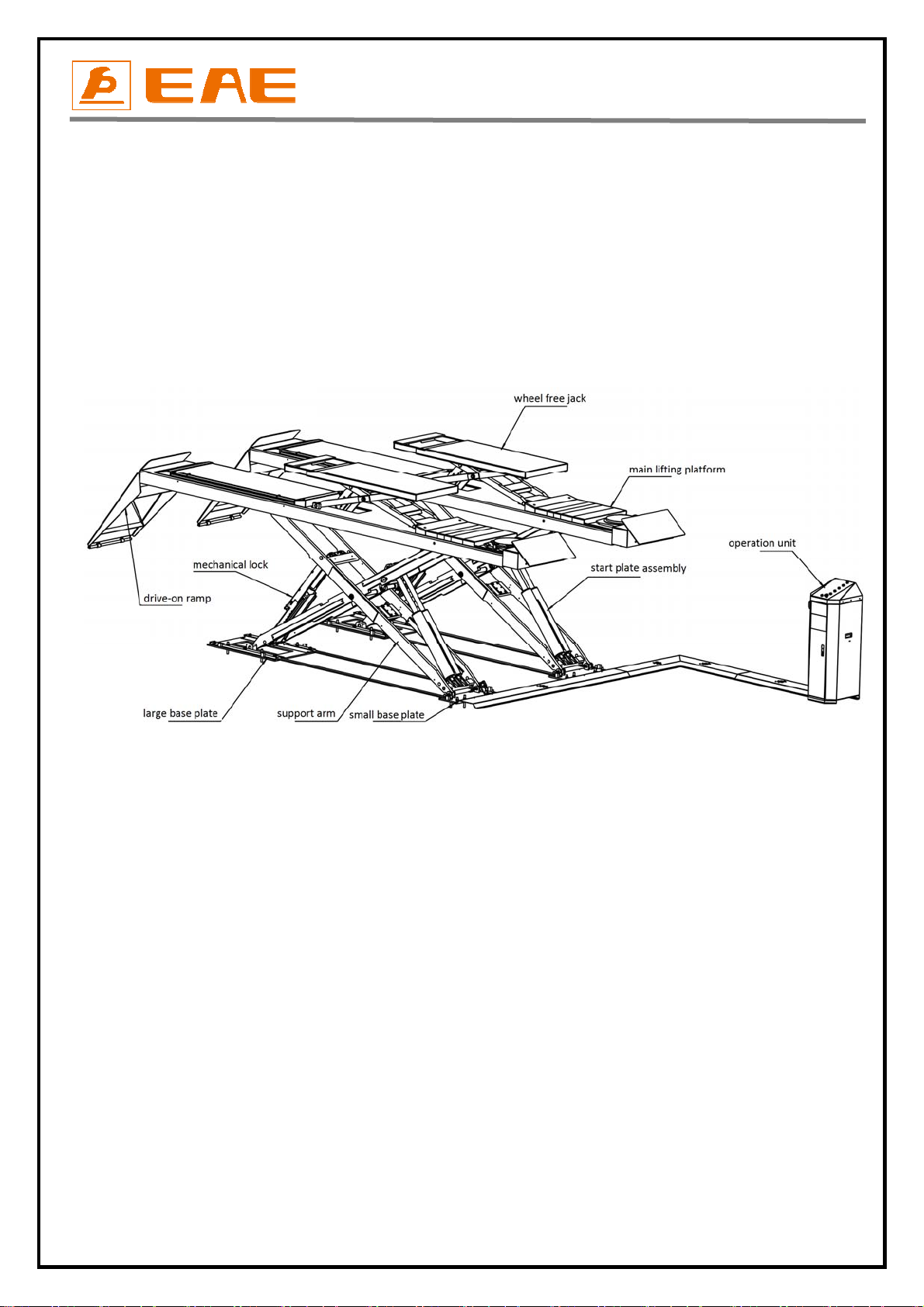
3.2Constructionofthelift..................................................................................................................................................9
3.3Dimensions..................................................................................................................................................................10
3.4Safetydevicedescriptions...........................................................................................................................................11
3.5Technicaldata.............................................................................................................................................................12
INSTALLATIONINSTRUCTIONS...............................................................................................................................12
4.1Preparationsbeforeinstallation.................................................................................................................................12
4.2Installationattentions.................................................................................................................................................13
4.3GeneralInstallationSteps...........................................................................................................................................14
4.4Itemstobecheckedafterinstallation........................................................................................................................16
OPERATIONINSTRUCTIONS...................................................................................................................................17
5.1Precautions.................................................................................................................................................................17
5.2Descriptionsofcontrolpanel......................................................................................................................................17
5.3Flowchartforoperation.............................................................................................................................................18
5.4Operationinstructions................................................................................................................................................18
TROUBLESHOOTING.............................................................................................................................................20
MAINTENANCE......................................................................................................................................................21
Annex1,FloorPlan...........................................................................................................................................................22
Annex2,Electricalschemesandpartslist........................................................................................................................24
Annex3,Hydraulicschemesandpartslist.......................................................................................................................28
Annex4,Pneumaticschemeandpartslist.......................................................................................................................32
Annex5,Mechanicallyexplodeddrawingsandpartslist.................................................................................................33

Installation, Operation and Parts Manual
EE-6604 V2.BWF
- 4
SAFETYNOTES
1.1Operationofliftingplatforms
Thisliftisspeciallydesignedforliftingmotorvehicles.Usersarenotallowedtouseitforanyotherpurposes.Theapplicablenational
regulations,lawsanddirectivesmustbeobserved.
Onlyusersaged18orabovewhohavebeeninstructedonhowtooperatetheliftingplatformandhaveproventheirabilitytodosotothe
owneraretobeentrustedwithunsupervisedoperationofliftingplatforms.Thetaskofoperatingtheliftingplatformsmustbegrantedin
writing.
Beforeloadingavehicleontotheliftingplatform,usersshouldstudytheoriginaloperationinstructionsandfamiliarizethemselveswith
theoperatingproceduresinseveraltrialruns.
1.2Checkingoftheliftingplatforms
Checksaretobebasedonthefollowingdirectivesandregulations:
Basicprinciplesfortestingliftingplatforms
Thebasicsafetyrequirementsstipulatedinthedirective2006/42/EC
HarmonizedEuropeanstandards
Theapplicableaccidentpreventionregulations
Thechecksaretobeorganizedbytheuseroftheliftingplatform.Theuserisresponsibleforappointinganexpertorqualifiedpersonto
performchecking.
Theuserbearsspecialresponsibilityifemployeesofthecompanyareappointedasexpertsorqualifiedpersons.
1.2.1Scopeofchecking
Regularcheckingessentiallyinvolvesperformingavisualinspectionandafunctionaltest.Thisincludescheckingtheconditionofthe
componentsandequipment,checkingthatthesafetysystemsarecompleteandfunctioningproperlyandthattheinspectionlogbookis
completelyfilledin.Thescopeofexceptionalcheckingdependsonthenatureandextentofanystructuralmodificationorrepairwork.
1.2.2Regularchecking
Afterinitialcommissioning,liftingplatformsaretobecheckedbyaqualifiedpersonatintervalsofnotlongerthanoneyear.
Aqualifiedpersonissomebodywiththetrainingandexperiencerequiredtopossesssufficientknowledgeofliftingplatformsandwhois
sufficientlyfamiliarwiththepertinentnationalregulations,accidentpreventionregulationsandgenerallyacknowledgedrulesof
engineeringtobeabletoassessthesafeoperatingconditionofliftingplatforms.
1.2.3Exceptionalchecking
Liftingplatformswithaliftheightofmorethan2metersandliftingplatformsintendedforusewithpeoplestandingundertheload
bearingelementsoftheloadaretobecheckedbyanexpertpriororreusefollowingstructuralmodificationsandmajorrepairstoload
bearingcomponents.
Anexpertissomebodywiththetrainingandexperiencerequiredtopossessspecialistknowledgeofliftingplatformsandwhois
sufficientlyfamiliarwiththepertinentnationalworksafetyregulations,accidentpreventionregulationsandgenerallyacknowledged
rulesofengineeringtobeabletocheckandgiveanexpertoptiononliftingplatforms.

Installation, Operation and Parts Manual
EE-6604 V2.BWF
- 5
1.3Importantsafetynotices
1.3.1Recommedforindooruseonly,DOnotexposethelifttorain,snoworexcessivemoisture.
1.3.2Onlyusethisliftonasurfacethatisstable,levelanddryandnotslippery,andcapableofsusutainingtheload.Donotinstallthe
liftonanyasphaltsurface.
1.3.3Readandunderstandallsafetywarningsbeforeoperatingthelift.
1.3.4Donotleavethecontrolswhiletheliftisstillinmotion.
1.3.5Keephandsandfeetawayfromanymovingparts.Keepfeetclearoftheliftwhenlowering.
1.3.6Onlytheseproperlytrainedpersonnelcanoperatethelift.
1.3.7Donotwearunfitclothessuchaslargeclotheswithflounces,tires,etc,whichcouldbecaughtbymovingpartsofthelift.
1.3.8Topreventevitableincidents,surroundingareasoftheliftmustbetidyandwithnothingunconcerned.
1.3.9Theliftissimplydesignedtolifttheentirebodyofvehicles,withitsmaximumweightwithintheliftingcapacity.
1.3.10Alwaysinsurethesafetylocksareengagedbeforeanyattempttoworknearorunderthevehicle.Neverremovesafetyrelated
componentsfromthelift.Donotuseifsafetyrelatedcomponentsaredamagedormissing.
1.3.11Donotrockthevehiclewhileontheliftorremoveanyheavycomponentfromvehiclethatmaycauseexcessiveweightshift.
1.3.12Checkatanytimethepartsofthelifttoensuretheagilityofmovingpartsandtheperformanceofsynchronization.Ensureregular
maintenanceandifanythingabnormaloccurs,stopusingtheliftimmediatelyandcontactourdealersforhelp.
1.3.13Lowerthelifttoitslowestpositionanddoremembertocutoffthepowersourcewhenservicefinishes.
1.3.14Donotmodifyanypartsoftheliftwithoutmanufacturer’sadvice.
1.3.15Iftheliftisgoingtobeleftunusedforalongtime,usersarerequiredto:
a.Disconnectthepower;
b.Emptytheoiltank;
c.Lubricatethemovingpartswithgrease.
WARNING:thewarnings,cautionsandinstructionsdiscussedinthisinstructionmanualcannotcoverallpossibleconditionsand
situationsthatmayoccur.Itmustbeunderstoodbytheoperatorthatcommonsenseandcautionarefactorswhichcannotbebuilt
intothisproduct,butmustbesuppliedbytheoperator.
Attention:Forenvironmentprotection,pleasedisposethedisusedoilinaproperway.

Installation, Operation and Parts Manual
EE-6604 V2.BWF
- 6
1.4Warninglabels
Allsafetywarninglabelsareclearlydepictedonthelifttoensurethattheoperatorisawareofandavoidthedangers
ofusingtheliftinanincorrectmanner.Thelabelsmustbekeptcleanandtheyhavetobereplacedifdetachedor
damaged.Pleasereadcarefullythemeaningofeachlabelandmemoriesthemforfutureoperation

Installation, Operation and Parts Manual
EE-6604 V2.BWF
- 7
1.5Potentialsafetyrisks
1.5.1Mainsvoltage
Insulationdamageandotherfaultsmayresultinaccessiblecomponentsbeinglive
Safetymeasures:
Onlyeverusethepowercordprovidedoratestedpowercord.
Replacewireswithdamagedinsulation.
Donotopentheoperatingunit.
1.5.2Riskofinjury,dangerofcrushing
Intheeventofexcessivevehicleweight,incorrectmountingofthevehicleoronremovingheavyobject,
thereisariskofthevehiclefallingofftheliftingplatformortippingup.
Safetymeasures:
Theliftingplatformisonlyevertobeemployedfortheintendedpurpose.
CarefullystudyandheedalltheinformationgiveninSection1.4.
Observethewarningnoticesforoperation.
1.6Noiselevel
Noiseemittedduringoperatingtheliftshouldbelessthan70dB.Foryourhealthconsideration,itissuggestedtoplaceanoisedetectorin
yourworkingarea.

Installation, Operation and Parts Manual
EE-6604 V2.BWF
- 8
PACKING,STORAGEANDTRANSPORTATION
Packing,lifting,handling,transportingoperationsmustbeperformedonlybyexperiencedpersonnelwith
appropriateknowledgeoftheliftandafterreadingthismanual.
2.1Theliftwasdismantledinto3partsfortransportation
NamePackedbyDimensionWeightQuantity
ControlcabinetWoodencase510*480*130084KG1
PowersideplatformCartonwithwoodenbase5100*700*3601550KG1
ThesecondaryplatformCartonwithwoodenbase5100*700*3601550KG1
RampBubblefilm1300*680*250106KG1
2.2Storage
Thepacksmustbekeptinacoveredandprotectedareainatemperaturerange0f‐10℃to+40℃.Theymustnotbeexposedtodirect
sunlight,rainorwater.
Stackingthepacks
Weadviseagainststackingbecausethepacksarenotdesignedforthistypeofstorage.Thenarrowbase,heavyweightandlargesizeof
thepacksmakestackingdifficultandpotentiallydangerous.
Ifstackingisunavoidable,useallappropriateprecautions:
‐neverstacktomorethan2metersinheight.
‐nevermakestacksofsinglepacks.Alwaysstackpairsofpacksinacrosspatternsothatthebaseisbiggerandtheresultingstackismore
stable.Oncethestackiscomplete,restrainitusingstraps,ropesorothersuitablemethods.
Amaximumoftwopackscanbestackedonlorries,incontainers,andinrailwaywagons,onconditionthatthepacksarestrapped
togetherandrestrainedtostopthemfalling.
2.3Liftingandhandling
Thepackscanbeliftedandtransportedonlybyusinglifttrucks.Thecenterofgravityandlashingpointsaremarkedonthe
packaging.Neverattempttohoistortransporttheunitusingliftingslings.
Openingthepacks
Whentheliftisdeliveredmakesurethatithasnotbeendamagedduringtransportationandthatallthepartsspecifiedonthepacking
listarepresent.
Packsmustbeopenedadoptingalltheprecautionsrequiredtoavoidinjurytopersons(keepatasafedistancewhencuttingthestraps)
ordamagetopartsofthemachine(becarefulthatnopartsaredroppedwhileyouareopeningthepacking)
Takespecialcarewiththehydraulicpowerunit,thecontrolpanelandtheplatformcylinder.

Installation, Operation and Parts Manual
EE-6604 V2.BWF
- 9
PRODUCTDESCRIPTIONS
3.1Generaldescriptions
Thismodelissurfacemountedandismainlycomposedbyliftingplatforms,baseplates,oilcylindersandasetofoperationunit.Thegear
pumpworkswhenpowersupplyisconnectedandmeanwhileoilinthepumppushesupwardsthepistonsofoilcylinders.Thus,scissor
bracketsoftheliftriseaccordingly.Themechanicallockwillautomaticallyengagedincaseoffailureofhydraulicsystem.
Besides,designslike24Vworkingvoltageofcontrolboxandlimitswitch,low‐heightalarmingbuzzer,anti‐surgevalves,etchavefully
consideredyourpersonalsecurity.
3.2Constructionofthelift

Installation, Operation and Parts Manual
EE-6604 V2.BWF
- 10
3.3Dimensions

Installation, Operation and Parts Manual
EE-6604 V2.BWF
- 11
3.4Safetydevicedescriptions
NO.SafetydeviceFunction
1Anti‐surgevalve
Slowdownthefallingspeedofliftingplatformincasethereis
leakageofhydraulicoilhoses.
2Mechanicallockforliftingplatform
Protecttheliftingplatformfromfallingdownincaseoil
cylinderslossforcescausedbybreakdownofhydraulicsystem.
324Voperationvoltage Safetyvoltageforoperators.
5Maxheightlimitswitchforwheeljack
Stoprisingatamaximumheightof450mmabovelifting
platform.
6Tip‐upprotectionforwheeljackift
Protectauxiliaryliftfromtipping‐up,incaseloadonitisnot
evenlydistributed.
7Tip‐upprotectionforliftingplatforms
Protectliftingplatformfromtipping‐up,incaseloadonitisnot
evenlydistributed.
8Maxheightlimitswitchforliftingplatform Stoprisingatamaximumheightof1900mmaboveground.

Installation, Operation and Parts Manual
EE-6604 V2.BWF
- 12
3.5Technicaldata
Ratedcapacity4000KG
Fullraisedheight 1900mm
Fullloweredheight 180mm
Fullraisedtime(withratedload)≤55s
Fullloweredtime(withratedload)≤55s
Hydraulicworkingpressure(Mpa)20MPa
Pneumaticworkingpressure(Bar)6‐8kg/cm²
Ratedcapacityofthesecondarylift 4000KG
Fullraisedheightofthesecondarylift 450mm
Oiltankvolume 18L
INSTALLATIONINSTRUCTIONS
4.1Preparationsbeforeinstallation
4.1.1Spacerequirements.
Referto3.3forthedimensionsofthelift.Theremustalsobeaclearanceofatleast1meterbetweentheliftingplatformandfixed
elements(e.g.wall)inallliftingpositions.Theremustbesufficientspaceattheendsoftheliftingplatformfordrivingvehiclesonandoff.
Tostopvehiclescollidingwiththeceiling,itisadvisabletofitanoverheadlightbarrierinlowceilingbuildings.
4.1.2Foundationsandconnections
Theusermusthavethefollowingworkperformedbeforeerectingthelift.
Constructionofthefoundationfollowingconsultationwiththemanufacturer’scustomerserviceoranauthorizedserviceagent.
Routingofthewiringtotheinstallationlocation.Theusermustprovidefuseprotectionfortheconnection.
Routingofthecompressedairconnectiontotheinstallationlocation.Theusermustinstallaserviceunitupstreamofthe
connection.
Referalsotothecorrespondinginformationinthecommissioninginstructions.
Requirementsforpowersupplycableoftheinstallationsite:atleast2.5mm2wirecorefor3Phpowerand4.0mm2wirecorefor1Ph
power.
4.1.3Foundationspreparations
PleaserefertoAnnex1forfloordimensions.

Installation, Operation and Parts Manual
EE-6604 V2.BWF
- 13
4.1.4Toolsandequipmentsneededforinstallation
ToolName Specification Qty
ElectricaldrillWithD16andD18drillbit.1
OpenspannerD17‐19mm2
AdjustablespannerbiggerthanD30mm1
Crosssocketscrewdriver PH21
Quickspannerhandleadapter/Ratchet 1
Socketspanner D24mm1
Levellingdevice 1
Hammer 10pounds 1
Trucklift Capacitymorethan2500KG1
Liftingstring Capacity,1000KG 2
LiftingstringCapacity,2000KG1
Torquespanner MD4001
4.1.5Checkingparts
Unfoldthepackageandcheckifanypartsmissedasperthefollowinglist.Donothesitatetocontactusincaseanypartsmissed,butif
youdonotcontactusandinsistinstallinguponthelackofsomeparts,weaswellasourdealerswillnotbearanyresponsibilityforthis
andwillchargeforanypartssubsequentlydemandedbythebuyer.
S/NNameSpecificationQty
1Liftingplatform 66042
2ExpansionboltM16*12016
3Controlcabinet/1
4Drive‐onramp6604V2‐A92
5ProtectivecoverA(L=2200)6604V2‐A131
6ProtectivecoverB(L=1000)6604V2‐A141
7ProtectivecoverC(L=1000)6604V2‐A151
8ProtectivecoverD(L=1000)6604V2‐A161
9Crosssocketcapheadtappingscrew ST4.8*3520
10PlasticexpansiontubeM10*4020
11Crosssocketcapheadscrew M6*124
12Hexnut M64
13Flatwasher M64
4.2Installationattentions
4.2.1Jointsofoilhoseandwiringmustbefirmlyconnectedinordertoavoidleakageofoilhoseandloosenessofelectricalwires.
4.2.2Allboltsshouldbefirmlyscrewedup.

Installation, Operation and Parts Manual
EE-6604 V2.BWF
- 14
4.2.3Donotplaceanyvehicleontheliftinthecaseoftrialrunning.
4.3GeneralInstallationSteps
Step1:Chooseinstallationsite.
Useaforklifttoplacethetwoliftingplatformsintoinstallationsiteasrequired.
SeeAnnex1forspacerequirementsontheinstallationsite.
Step2:Connecthydraulicoilhoses.
Connecttheoilhosestothepowerunitasperthediagramforoilhoseconnection. Annex3.
Attention:Connectasperthemarksonthehosesanddonotcontaminatethehydrauliccomponentsduringtheconnection.
Step3:Connectpneumatichoses.
ConnectthepneumaticreleasesystembythediagramofairhoseconnectioninAnnex4.
Attention:Connectasperthemarksonthehosesanddonotcontaminatethepneumaticcomponentsduringtheconnection.
Step4:Connectelectricalwires.
Refertotheelectricalconnectionscheme.Connectthepowersupplyandthequickconnectersforlimitswitch.
(Forthreephasepowersupply,iftheliftdoesn'traiseandthemotormayturninthewrongdirection,insuchevent,interchangewiresU,V
inthecontrolcabinet).
Step5:Fillwithhydraulicoil.
ONLYCLEANANDFRESHOILONLY.Liftmustbefullyloweredbeforechangingoraddinghydraulicoil.
Normallyitneeds22litersofhydraulicoil.
Initially,fillthetankfullwithabout18Lofhydraulicoil.Runtheliftforseveralcyclesandaddanother4Lintothetank.Thelevelofoil
shallreachthetippetsvolumemarkofthetank.Runtheliftforseveralcyclesandaddmoreoiluntiltheliftingplatformcanreachits
maximumheight.
Note:Asrunningspeedoftheliftismainlydecidedbytheviscosityofthehydraulicoil,wesuggestusingNO.46hydraulicoilwhen
averagetemperatureofthelocationisabove18degreeCelsiusandusingNO.32hydraulicoilwhentemperatureisbelow18degree
Celsius.Changetheoil6monthsafterinitialuseandchangeonceperyearthereafter.
Step6:Levelling
Checktheconnectionofthehydraulicandelectricalsystembeforelevellingoperation
Reviewoperationinstructionsandgetfamiliarwithliftcontrolsbyrunningtheliftthroughafewcyclesbeforelevellingopearion.
Attention:Leveltheplatformsbeforeconnectingmaxheightlimitswitchbecauseifnot,platformsmaynotrisetothehighestposition.
Theoperatorneedstoknowclearwhichlevellingvalvecontrolswhichplatform.Thiscouldbejudgedbythewaythattheoilhosewas
connectedorbytrialraisingorlowering.
Checktheconnectionofthehydraulicandelectricalsystembeforelevellingoperation
Reviewoperationinstructionsandgetfamiliarwithliftcontrolsbyrunningtheliftthroughafewcyclesbeforelevelingopearion.
Levellingthemainlift.
1)TurnonthemainpowerswitchandturntheselectionswitchSA2tothemainliftandSA1to“Levelling”status.Turnthetwohandlesof
levellingvalvetothefollowingstatus.

Installation, Operation and Parts Manual
EE-6604 V2.BWF
- 15
2)PushtheUPbuttontoraisetheplatformstothemaxheightandthenlowertotheminimumheight.Repeatthisfor3cycles.Pay
attendiontopushtheUPbuttonveryslightlyandslowlywhentheplatformsalmostreachtothemaxheight.Afterthat,engagethe
mechanicalsafetylocksandpushDOWNIandDOWNIItocompletelylowertheplatforms.Thisstepmayneedsprettylongtimeasthere
remainedairintheoilcylindersandnoloadontheplafroms.
3)Repeatthecyclesofstep2fortwoorthreetimes.Turnoffthetwolevellingvalveswhenplatformsarefullylowered.Turnthetwo
handlestothefollowingstatus.
4)TurnSA1tonormalworkingstatusandpushUPbuttontocheckthesynchronization.(Normally,thetwoplatformsarenot
synchronizedtillthisstep).
5)Ifnotbeingsynchronizedandoneplatformrisesfasterthantheother,openthelevellingvalvethatcontrolstheslowerplatformand
turnSA1tolevellingstatus,pushtheUPbuttonslightlyuntilbothplatformsareatthesameheight.Closethelevellingvalve.
6)TurnSA1tonormalworkingstatusandcheckthesynchronization.
7)IFstillnotbeingsynchronized,repeatstep4tostep6untilbothplatformsaresynchronized.
Levellingthesecondarylift
1)TurnSA2oncontrolpaneltoJACKandturnSA1tolevelingstatus.
2)PushUPbuttonuntilbothplatformofthejackgoutmosttoptobleedairinthecylinders.
3)PushDOWNI,untiljackslowertothelowestposition.
PUSHUPBUTTONTOCHECK.THEJACKSSHOULDBESYNCHRONIZEDBYTHISSTEP.
Repeattheabovelevellingstepsuntilsynchronizationreached.

Installation, Operation and Parts Manual
EE-6604 V2.BWF
- 16
Step7:Fixbaseframeswithexpansionbolts.
1.Drillanchorholesforexpansionboltsonthegroundwithanelectricaldrill.Makesuretodrillvertically.
2.Removethoroughlythedebrisanddustinholesandascertainthatthepostsstayrightuponthecirclepreviouslymarkedbychalk.
3.Hammerinandsecureexpansionbolts.
Step8:Fixoilhoseprotectioncovers.
4.4Itemstobecheckedafterinstallation.
S/NCheckitemsYESNO
1Screwtorqueofexpansionbolts:60‐80N•m;
2Risingspeed≥20mm/s;
3Noisewithratedload≤75db;
4Groundingresistance:notbiggerthan4Ω;
5Heightdifferenceofthetwoplatform≤5mm;
6Mechanicallocksarerobustandsynchronizedwhenrunningwithratedload;
7Ifthecontrolbuttonworksas“holdtorun”?
8Iflimitswitchesworkwell?
9Ifgroundingwireisconnected?
10Iftheliftrisesandlowerssmoothly?
11Ifthereisnoabnormalnoticeduringrunningwithratedload?
12Ifthereisnooilleakagewhenrunningwithratedload?
13Ifthereisnoairleakagewhenrunningwithratedload?
14Ifexpansionbolts,nutsorcirclipsarewellsecured?
15Ifmaxliftingheightis1900mm?
16IfSafetyadvices,nameplateandlogosareclear?

Installation, Operation and Parts Manual
EE-6604 V2.BWF
- 17
OPERATIONINSTRUCTIONS
5.1Precautions
5.1.1Checkallthejointsofoilhose.Onlywhenthereisnoleakage,theliftcanstartwork.
5.1.2Thelift,ifitssafetydevicemalfunctions,shallnotbeused.
5.1.3Itshallnotliftorloweranautomobileifitscenterofgravityisnotpositionedmidwayoftherunways.Failuretodosomaycause
damagetopropertyandpersonel.
5.1.4Operatorsandpersonnelconcernedshouldstandinasafetyareaduringliftingandloweringprocess.
5.1.5Whentheplatformareraisedtothedesiredheight,switchoffthepowertopreventanywrongoperationdonebyunconcerned
people.
5.1.6.Makesurethesafetylockoftheliftisengagedbeforestartworkingunderthevehicleandnopeopleunderthevehicleduringlifting
andloweringprocess.
5.2Descriptionsofcontrolpanel
POS.Name Function
FAAlarmbuzzer Safetywarning
SB1 UPbutton Controltherisingmovement
SB3 DOWNbutton Controltheinitialloweringmovement
SB4DOWNbutton Controlthefinalloweringmovement
SB2LOCKbutton Engagethemechanicalsafetylocks
SB Emergencystop Stoppowerinemergencycases
HL Powerindicator Showifpowerison
QS Mainswitch Poweron/off
SA1Selectionswitch Controlworkingorlevellingcondition
SA2Selectionswitch Mainliftorsecondarylift

Installation, Operation and Parts Manual
EE-6604 V2.BWF
- 18
Turnonthepowerswitch
PushUPbutton
Motordrivesthegearpumpwork
Theliftrised
Cylinderpistondrivestherunwaymoveup
Theplatformsrisetorelease
safetylocks
Thelift lowered
PushDOWNIIwhenplatforms
stoploweringatadistanceof
600mmaboveground
Turnonthepowerswitch
Push DOWNIbutton
5.3Flowchartforoperation
5.4Operationinstructions
Toavoidpersonalinjuryand/orpropertydamage,permitonlytrainedpersoneltooperatethelift.Afterreviewingthese
instructions,getfamiliarwithliftcontrolsbyrunningtheliftthroughafewcyclesbeforeloadingvehicleonlift.Alwaysliftthe
vehicleusingbothplatforms.Neverraisejustoneend,onecorneroronesideofvehicle.
Thenormalusersarenotallowedtoopenthedoorofcontrolcabinet.Selectionswitchinthecontrol
cabinetneedstobeturnedto‘working’beforeusingthelifttoraisevehicles.
Usingthemainlift.Liftingcapacity:4000KG
Raisethelift
Makesurevehicleisneitherfrontnorrearheavyandcenterofbalanceshouldbecenteredoverthelift.
1.Driveandparkthevehiclemidwaybetweentwoplatforms.Makesurethevehicleiscorrectlypositionedandsecuredagainstrolling.
2.Pushthe“UP”buttononthecontrolpaneltoliftthevehicleabithigherfromthegroundandcheckagainifthevehicleisinasafe
position.
3.Havingraisedthevehicletotheheightneeded,pushthe“SafetyLock”buttontoensurethemechanicalsafetylockisengaged.Push
the“EmergencyStop”andcheckagainthestabilitybeforeperformingmaintenanceorrepairwork.
Lowerthelift
Whenloweringtheliftpaycarefullattentionthatallpersonnelandobjectsarekeptclear.
1.Switchon.
2.Push”DOWNI”buttontolowerthelift.Firstly,theliftwillautomaticallyrisetodisengagethemechanicallocks.Thentheliftlowers.It
willstoploweringwhenclearancebetweentheplatformsandthegroundreachesto600mm.
3.Push“DOWNII”buttontocontinueloweringtheplatforms.Alarmingbuzzwillbeheard.
Raising
Lowering

Installation, Operation and Parts Manual
EE-6604 V2.BWF
- 19
Usingthesecondarylift.Liftingcapacity:4000KG
Raisethesecondarylift
1.Turntheselectionswitchonthecontrolpanelto“secondarylift”.
2.Placerubberpadsunderthepick‐uppointsofvehicle.Whenitisnecessarytousetheplatformextensions,push“UP”buttontoraise
platformsofthejackabitovertheplatformsofmainliftandpullouttheextensions.
3.Push“UP”buttonandcheckagainiftherubberpadsaredirectlyunderthepick‐uppointsofthevehicle,whentheyareverycloseto
thechassis.
4.Keeponpushing”UP”buttonuntilliftingplatformelevatestotheheightexpected.
Lowerthesecondarylift
Attention:incasetheplatformextensionsofthejackareused,theoperatorneedstopushtheminthewhenwheelsoftheserviced
vehiclefallonsteadilytheplatformsofthemainlift.
1.Turntheselectionswitchonthecontrolpanelto“secondarylift”..
2.Push“DOWNI”buttonforloweringmovement.
3.Takeawayrubberpads.

Installation, Operation and Parts Manual
EE-6604 V2.BWF
- 20
TROUBLESHOOTING
ATTENTION:Ifthetroublecouldnotbefixedbyyourself,pleasedonothesitatetocontactusforhelp.Wewillofferourserviceatthe
earliesttimewecan.Bytheway,yourtroubleswillbejudgedandsolvedmuchfasterifyoucouldprovideusmoredetailsorpicturesof
thetrouble.
TROUBLESCAUSESOLUTION
Motordoesnotrunandwillnot
raise
Thewireconnectionisloose.Checkandmakeagoodconnection.
ThemotorisburntReplaceit.
Thelimitswitchisdamagedorthewire
connectionisloose.
Connectitoradjustorreplacethelimit
switch.
Motorrunsbutwillnotraise
Themotorrunreversely.Checkthewireconnection.
Overflowvalveislooseorjammed.Cleanoradjustit.
Thegearpumpisdamaged.Replaceit.
Oillevelistoolow.Addoil.
Theoilhosebecamelooseordroppedoff.Tightenit.
Thecushionvalvebecamelooseorjammed.Cleanoradjustsit.
Platformsgodownslowlyafter
beingraised
Theoilhoseleaks.Checkorreplaceit.
Theoilcylinderisnottightened.Replacetheseal.
Thesinglevalveleaks.Cleanorreplaceit.
Theoverflowvalveleaks.Cleanorreplaceit.
Electricalunloadingvalveleaks.Cleanorreplaceit.
Raisingtooslow
Theoilfilterisjammed.Cleanorreplaceit.
Oillevelistoolow.Addoil.
Theoverflowvalveisnotadjustedtotheright
position.
Adjustit.
Thehydraulicoilistoohot(above45°).Changetheoil.
Thesealofthecylinderisabraded.Replacetheseal.
Loweringtooslow
Thethrottlevalvejammed.Cleanorreplace.
Thehydraulicoilisdirty.Changetheoil.
Theanti‐surgevalvejammed.Cleanit.
Theoilhosejammed.Replaceit.
Table of contents
Other EAE Scissor Lift manuals