EAE EE-6603BWF Guide

Installation, Operation
and Parts Manual
Model No. EE-6603BWF
Long platform scissor lift,
In-ground Installation
Manual Levelling
Lifting Capacity 4200KG/ 5000KG
Please read this entire manual carefully and completely before installation or operation of the lift.
2017.07.27- 540104106

Installation, Operation and Parts Manual
EE-6603BWF
2
IMPORTANT NOTES
Before start up, connecting and operating EAE products, it is absolutely essential that the operating instructions/owner’s manual and, in
particular the safety instructions are studied carefully. By doing so you can eliminate any uncertainties in handling EAE products and thus
associated safety risks up front; something which is in the interest of you own safety and will ultimately help avoid damage to the device,
When an EAE product is handed over to another person, not only the operating instructions but also the safety instructions and
information on its designated use must be handed over to the person.
By using the product you agree the following conditions:
Copy right
The enclosed instructions are the property of EAE or its supplier, and are protected against duplication and reproduction by copyright
laws, international agreements, and other domestic legislation. The reproduction or disclosure of instructions or an extract thereof is
prohibited and offenders are liable to prosecution; EAE reserves the right or initiates criminal proceedings and asserts claims for damages
in the event of infringements.
Warranty
The use of non-approved hardware will result in a modification of our products and thus to the exclusion of any liability or warranty, even
if such hardware has been removed again in the interim.
It is not permissible to make any changes to our products and these are not only to be used together with genuine accessories and
genuine replacement parts. Otherwise any warranty claims will be invalid.
Liability
The liability of EAE is limit to the amount that the customer has actually paid for this product. This exclusion of liability does not apply to
damages caused through willful misconduct or gross negligence on the part of EAE.

Installation, Operation and Parts Manual
EE-6603BWF
3
IMPORTANT NOTES .............................................................................................................................................. 2
SAFETY NOTES...................................................................................................................................................... 4
1.1 Operation of lifting platforms.......................................................................................................................................4
1.2 Checking of the lifting platforms...................................................................................................................................4
1.3 Important safety notices...............................................................................................................................................5
1.4 Warning labels..............................................................................................................................................................6
1.5 Potential safety risks.....................................................................................................................................................7
1.6 Noise level.....................................................................................................................................................................7
PACKING, STORAGE AND TRANSPORTATION ......................................................................................................... 8
2.1 The lift was dismantled into 3 parts for transportation................................................................................................8
2.2 Storage..........................................................................................................................................................................8
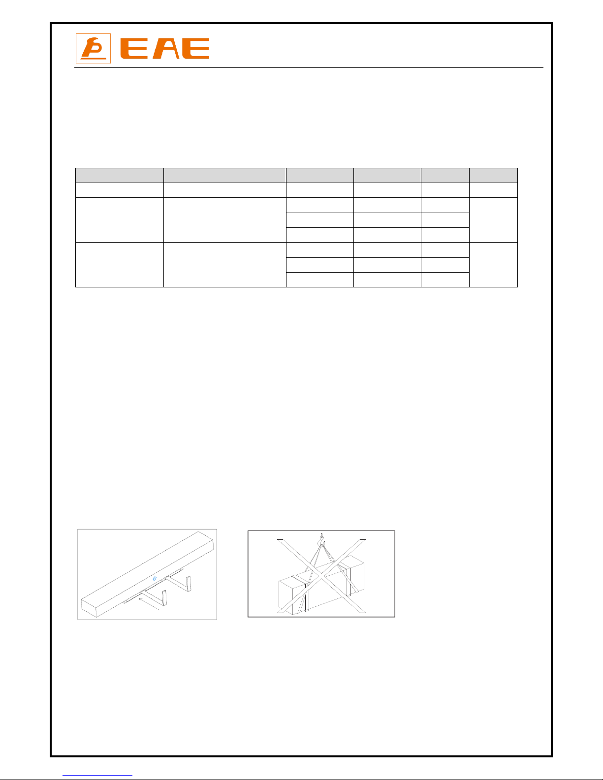
2.3 Lifting and handling ......................................................................................................................................................8
PRODUCT DESCRIPTIONS ...................................................................................................................................... 9
3.1 General descriptions .....................................................................................................................................................9
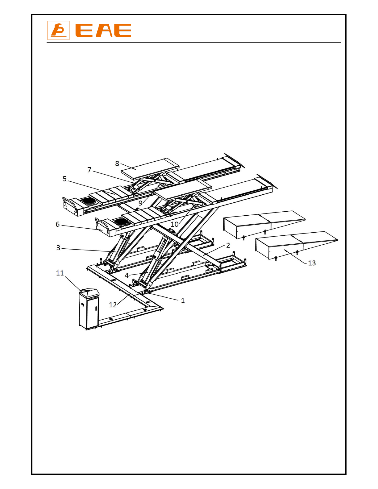
3.2 Construction of the lift ..................................................................................................................................................9
3.3 Dimensions..................................................................................................................................................................10
3.4 Technical data.............................................................................................................................................................11
INSTALLATION INSTRUCTIONS ............................................................................................................................ 11
4.1 Preparations before installation .................................................................................................................................11
4.2 Installation attentions.................................................................................................................................................12
4.3 General Installation Steps...........................................................................................................................................13
4.4 Items to be checked after installation. .......................................................................................................................14
OPERATION INSTRUCTIONS ................................................................................................................................ 15
5.1 Precautions .................................................................................................................................................................15
5.2 Control panel descriptions ..........................................................................................................................................15
5.3 Working flow chart .....................................................................................................................................................16
5.4 Operation instructions ................................................................................................................................................16
TROUBLE SHOOTING .......................................................................................................................................... 18
MAINTENANCE................................................................................................................................................... 19
Annex 1, Floor Plan for recessed installation....................................................................................................................21
Annex 2, Electrical diagrams and parts list.......................................................................................................................25
Annex 3, Hydraulic diagrams and parts list ......................................................................................................................30
Annex 4, Pneumatic connections and parts list ................................................................................................................35
Annex 5, Mechanically exploded drawings and parts list.................................................................................................36

Installation, Operation and Parts Manual
EE-6603BWF
4
SAFETY NOTES
1.1 Operation of lifting platforms
This lift is specially designed for lifting motor vehicles. Users are not allowed to use it for any other purposes. The applicable national
regulations, laws and directives must be observed.
Only users aged 18 or above who have been instructed on how to operate the lifting platform and have proven their ability to do so to the
owner are to be entrusted with unsupervised operation of lifting platforms. The task of operating the lifting platforms must be granted in
writing.
Before loading a vehicle onto the lifting platform, users should study the original operation instructions and familiarize themselves with
the operating procedures in several trial runs.
Lift vehicle within the rated load. Don’t attempt to raise vehicles with excessive weight.
1.2 Checking of the lifting platforms
Checks are to be based on the following directives and regulations:
Basic principles for testing lifting platforms
The basic health and safety requirements stipulated in the directive 2006/42/EC
Harmonized European standards
The applicable accident prevention regulations
The checks are to be organized by the user of the lifting platform. The user is responsible for appointing an expert or qualified person to
perform checking. It must be ensure that the person chosen satisfies the requirements.
The user bears special responsibility if employees of the company are appointed as experts or qualified persons.
1.2.1 Scope of checking
Regular checking essentially involves performing a visual inspection and a functional test. This includes checking the condition of the
components and equipment, checking that the safety systems are complete and functioning properly and that the inspection log book is
completely filled in. The scope of exceptional checking depends on the nature and extent of any structural modification or repair work.
1.2.2 Regular checking
After initial commissioning, lifting platforms are to be checked by a qualified person at intervals of not longer than one year.
A qualified person is somebody with the training and experience required to possess sufficient knowledge of lifting platforms and who is
sufficiently familiar with the pertinent national regulations, accident prevention regulations and generally acknowledged rules of
engineering to be able to assess the safe operating condition of lifting platforms.
1.2.3 Exceptional checking
Lifting platforms with a lift height of more than 2 meters and lifting platforms intended for use with people standing under the load
bearing elements of the load are to be checked by an expert prior or reuse following structural modifications and major repairs to load
bearing components.
An expert is somebody with the training and experience required to possess specialist knowledge of lifting platforms and who is

Installation, Operation and Parts Manual
EE-6603BWF
5
sufficiently familiar with the pertinent national work safety regulations, accident prevention regulations and generally acknowledged
rules of engineering to be able to check and give an expert option on lifting platforms.
1.3 Important safety notices
1.3.1 Recommend for indoor use only. DO not expose the lift to rain, snow or excessive moisture.
1.3.2 Only use this lift on a surface that is stable and capable of sustaining the load. Do not install the lift on any asphalt surface.
1.3.3 Read and understand all safety warnings before operating the lift.
1.3.4 Do not leave the controls while the lift is still in motion.
1.3.5 Keep hands and feet away from any moving parts. Keep feet clear of the lift when lowering.
1.3.6 Only these properly trained personnel can operate the lift.
1.3.7 Do not wear unfit clothes such as large clothes with flounces, tires, etc., which could be caught by moving parts of the lift.
1.3.8 To prevent evitable incidents, surrounding areas of the lift must be tidy and with nothing unconcerned.
1.3.9 The lift is simply designed to lift the entire body of vehicles, with its maximum weight within the lifting capacity.
1.3.10 Always insure the safety locks are engaged before any attempt to work near or under the vehicle. Never remove safety related
components from the lift. Do not use if safety related components are damaged or missing.
1.3.11 Do not rock the vehicle while on the lift or remove any heavy component from vehicle that may cause excessive weight shift.
1.3.12 Check at any time the parts of the lift to ensure the agility of moving parts and the performance of synchronization. Ensure regular
maintenance and if anything abnormal occurs, stop using the lift immediately and contact our dealers for help.
1.3.13 Lower the lift to its lowest position and do remember to cut off the power source when service finishes.
1.3.14 Do not modify any parts of the lift without manufacturer’s advice.
1.3.15 If the lift is going to be left unused for a long time, users are required to:
a. Disconnect the power;
b. Empty the oil tank;
c. Lubricate the moving parts with hydraulic oil.
WARNING:The warnings, cautions and instructions discussed in this instruction manual cannot cover all possible conditions and
situations that may occur. It must be understood by the operator that common sense and caution are factors which cannot be built
into this product, but must be supplied by the operator.
Attention: For environment protection, please dispose the disused oil properly.

Installation, Operation and Parts Manual
EE-6603BWF
6
1.4 Warning labels
All safety warning labels are clearly depicted on the lift to ensure that the operator is aware of and avoid the dangers of using the lift in
an incorrect manner. The labels must be kept clean and they have to be replaced if detached or damaged. Please read carefully the
meaning of each label and memories them for future operation

Installation, Operation and Parts Manual
EE-6603BWF
7
1.5 Potential safety risks
1.5.1 Mains voltage
Insulation damage and other faults may result in accessible components being live.
Safety measures:
Only ever use the power cord provided or a tested power cord.
Replace wires with damaged insulation.
Do not open the operating unit.
1.5.2 Risk of injury, danger of crushing
In the event of excessive vehicle weight, incorrect mounting of the vehicle or on removing heavy object,
there is a risk of the vehicle falling off the lifting platform or tipping up.
Safety measures:
The lifting platform is only ever to be employed for the intended purpose.
Carefully study and heed all the information given in Section 1.4.
Observe the warning notices for operation.
1.6 Noise level
Noise emitted during operating the lift should be less than 70dB. For your health consideration, it is suggested to place a noise detector in
your working area.

Installation, Operation and Parts Manual
EE-6603BWF
8
PACKING, STORAGE AND TRANSPORTATION
Packing, lifting, handling, transporting operations must be performed only by experienced personnel with
appropriate knowledge of the lift and after reading this manual.
2.1 The lift was dismantled into 3 parts for transportation
Name
Packed by
Specification
Dimension
Weight
Quantity
Control cabinet
Wooden case
6603BWF
51*48*130cm
84KG
1
Power side platform
Carton with wooden base
*.42L.42T
463*65*46cm
1050KG
1
*.48L.42T
520*65*46cm
1120KG
*.51L.50T
550*65*46cm
1180KG
The opposite platform
Carton with wooden base
*.42L.42T
463*65*46cm
1050KG
1
*.48L.42T
520*65*46cm
1120KG
*.51L.50T
550*65*46cm
1180KG
2.2 Storage
The packs must be kept in a covered and protected area in a temperature range 0f -10℃to +40℃. They must not be exposed to direct
sunlight, rain or water.
Stacking the packs
We advise against stacking because the packs are not designed for this type of storage. The narrow base, heavy weight and large size of
the packs make stacking difficult and potentially dangerous.
If stacking is unavoidable, use all appropriate precautions:
-never stack to more than 2 meters in height.
-never make stacks of single packs. Always stack pairs of packs in a cross pattern so that the base is bigger and the resulting stack is more
stable. Once the stack is complete, restrain it using straps, ropes or other suitable methods.
A maximum of two packs can be stacked on lorries, in containers, and in railway wagons, on condition that the packs are strapped
together and restrained to stop them falling.
2.3 Lifting and handling
The packs can be lifted and transported only by using lift trucks. The center of gravity and lashing points are marked on the packaging.
Never attempt to hoist or transport the unit using lifting slings.
Opening the packs
When the lift is delivered make sure that it has not been damaged during transportation and that all the parts specified on the packing
list are present.
Packs must be opened adopting all the precautions required to avoid injury to persons (keep at a safe distance when cutting the straps)
or damage to parts of the machine (be careful that no parts are dropped while you are opening the packing)
Take special care with the hydraulic power unit, the control panel and the platform cylinder.

Installation, Operation and Parts Manual
EE-6603BWF
9
PRODUCT DESCRIPTIONS
3.1 General descriptions
This model is recessed mounted and is mainly composed by two lifting platforms and a set of power unit. The gear pump works making oil
in the pump will push upwards the pistons of oil cylinders. Thus, scissor brackets of the lift rise accordingly. In case of hydraulic failure, the
mechanical safety locking unit ensures no sudden fall of lifting platforms.
Besides, designs like 24V working voltage of control box and limit switch, low-height alarming buzzer, anti-surge valves, etc. have fully
considered your personal security.
3.2 Construction of the lift
1. Base frame assembly
2. Support arm of the main lift
3. Main oil cylinder and mechanical lock
4. Secondary oil cylinder and mechanical lock
5. Main lifting platform
6. Secondary lifting platform
7. Support arm of the wheel lift
8. Platform of the wheel lift
9. Main cylinder and lock of the wheel free lift
10. Secondary cylinder and lock of the wheel free lift
11. Control cabinet
12. Oil hose covers (for surface mount)
13. Drive-on ramp (for surface mount)

Installation, Operation and Parts Manual
EE-6603BWF
10
3.3 Dimensions
Specification
PW
RL
OL
L1
L2
*.42L
610
4200
4442
1320
970
*.48L
610
4800
5042
1520
1370
*.51L
610
5100
5342
1520
1570

Installation, Operation and Parts Manual
EE-6603BWF
11
3.4 Technical data
Specification
*.42L.42T
*.48L.42T/*.48L.50T
*.51L .50T
Rated capacity of the main lift
4200KG
4200KG/5000KG
5000KG
Applicable wheel track of the main lift
1100~1800mm
1100~1800mm
1100~1800mm
Applicable wheel base of the main lift
≤4000mm
≤4600mm
≤4900mm
Full raised height of the main lift
2060mm
Initial height of the main lift
360mm
Full raised time (with rated load)
≤50s
Full lowered time (with rated load)
≤50s
Rated capacity of the wheel free lift
3500KG
Applicable wheel track of the wheel free lift
1100~1800mm
Applicable wheel base of the wheel free lift
2100~2800mm
Full raised height of the wheel free lift
450
Hydraulic working pressure ( MPa )
24
24 / 29
29
Pneumatic working pressure (Bar)
6-8
Oil tank volume
18L
INSTALLATION INSTRUCTIONS
4.1 Preparations before installation
4.1.1 Space requirements.
Refer to 3.3 for the dimensions of the lift. There must also be a clearance of at least 1 meter between the lifting platform and fixed
elements (e.g. wall) in all lifting positions. There must be sufficient space at the ends of the lifting platform for driving vehicles on and off.
To stop vehicles colliding with the ceiling, it is advisable to fit an overhead light barrier in low ceiling buildings.
4.1.2 Foundations and connections
The user must have the following work performed before erecting the lift.
Construction of the foundation following consultation with the manufacturer’s customer service or an authorized service agent.
Routing of the wiring to the installation location. The user must provide fuse protection for the connection. Electrical system
connection must be done by licensed technicians. Requirements for power supply cable of the installation site: at least 2.5mm2
wire core for 3Ph power and 4.0mm2 wire core for 1Ph power.
Refer also to the corresponding information on the name plate and in the operation instructions. Before doing electrical
connection, make sure the lift is electrically adapt to the local power supply.
4.1.3 Foundations preparations
Please refer to Annex 1 for recessed floor dimensions.

Installation, Operation and Parts Manual
EE-6603BWF
12
4.1.4 Tools and equipment for installation
Tool name
Specification
Qty
Electrical drill
With D16 and D18 drill bit.
1
Open spanner
D17-19mm
2
Adjustable spanner
bigger than D30mm
1
Cross socket screw driver
PH2
1
Quick spanner handle adapter/ Ratchet
1
Socket spanner
D24mm
1
Levelling device
1
Hammer
10 pounds
1
Truck lift
Capacity more than 2500KG
1
Lifting strap
Capacity, 1000KG
2
Lifting strap
Capacity, 2000KG
1
4.1.5 Checking parts
Unfold the package and check if any parts missed as per the following list. Do not hesitate to contact us in case any parts missed, but if
you do not contact us and insist installing upon the lack of some parts, we as well as our dealers will not bear any responsibility for this
and will charge for any parts subsequently demanded by the buyer.
No.
Name
Specification
Qty
1
Power side lifting platform assembly
6603B-01
1
2
Secondary lifting platform assembly
6603B-02
1
3
Control cabinet
6603B
1
4
Rubber pad
38*120*160mm
4
5
Expansion bolt
M16*120
16
6
Air hose
D=8
2m
7
Air hose connector
PP-20 5*8
1
8
User's Manual
1
9
Key
1
10
Oil tank label
1
4.2 Installation attentions
4.2.1 Joints of oil hose and wiring must be firmly connected in order to avoid leakage of oil hose and looseness of electrical wires.
4.2.2 All bolts should be firmly screwed up.
4.2.3 Do not place any vehicle on the lift in the case of trial running.

Installation, Operation and Parts Manual
EE-6603BWF
13
4.3 General installation steps
Step 1: Dismantle the package and place lifting platforms into recessed pits with a forklift and lifting straps.
Raise the platform by using a forklift and 2 lifting straps until the mechanical lock is engaged. Dismantle the bolts that fix the platform and
its wooden package and then hoist the platform onto the expected installation site.
Attention 1: Avoid scratching the painting surface and hoses.
Attention 2: Before hoisting, make sure the hoses and wires are well protected against damage.
Attention 3: It is necessary to hold the platform during the hoisting process. Irrelevant person is not allowed in installation area.
Step 2: Connect hydraulic system.
Connect the oil hoses to the power unit as per the diagram for oil hose connection in Annex 3.
Attention: Connect as per the marks on the hoses and do not contaminate the hydraulic components during the connection.
Step 3: Connect the pneumatic release system
Connect the pneumatic release system by the diagram of air hose connection in Annex 4.
Attention: Do not contaminate the pneumatic components during the connection.
Step 4: Connect electrical wires.
Refer to Annex 2 when fix the electrical system.
Connect the wire connectors for raising and lowering limit switches
Connect the power supply cable to external electricity supply.
(For three phase power supply, if the lift doesn't raise and the motor may turn in the wrong direction, in such event, interchange wires U, V
in the control cabinet).
Step 5: Fill with hydraulic oil.
ONLY CLEAN AND FRESH OIL ONLY .Lift must be fully lowered before changing or adding hydraulic oil.
Pour 16 liters of hydraulic oil into the oil tank. The level of oil shall reach the tippets volume mark of the tank.
Run the lift for several cycles and add more oil until the lifting platform can reach its maximum height.
Note:As the viscosity of hydraulic oil may have influence on the running speed of the lift, it is suggested using NO.46 hydraulic oil when
average temperature of the location is above 18 degree Celsius and using NO.32 hydraulic oil when temperature is below 18 degree
Celsius. Change the oil 6 months after initial use and change once per year thereafter.
Step 6: Levelling
Check the connection of the hydraulic and electrical system before levelling operation
Review operation instructions and get familiar with lift controls by running the lift through a few cycles before leve lling
operation.
Attention: Level the platforms before connecting max height limit switch because if not, platforms may not rise to the highest position.
The operator needs to know clear which levelling valve controls which platform. This could be judged by the way that the oil hose was
connected or by trial raising or lowering.
Level the main lift.
1) Connect the power supply and turn on the main power switch.
2) Turn the selection switch on the control panel to the “lift” and the selection switch in the control cabinet to “levelling”mode and push
the “UP” button for 30 seconds. Normally at least one of the two runways start rising.
3) Turn on the levelling valve for the main lift at the hydraulic block and then push “UP” or “DOWN” button to adjust the height of one
lifting platform until it reaches the same height as the other one.
4) Turn off the valve.

Installation, Operation and Parts Manual
EE-6603BWF
14
5) Repeat the above levelling steps if synchronization is not achieved.
Level the wheel free lift
1) Turn the selection switch on the control panel to the” wheel free lift” and the selection switch in the control cabinet to
“levelling”mode.
2) Turn on levelling valve for the” wheel free lift” at the hydraulic block in the control unit.
3) Push the "UP” button until both lifting platforms of the jack go utmost top to bleed air in cylinders.
4) Turn off the ball valve.
5) Push DOWN I button till the platform of “wheel free lift” have fully lowered.
PUSH UP BUTTON TO CHECK. THE wheel free lift SHOULD BE SYNCHRONIZED BY THIS STEP.
IF STILL NOT,
Turn on the valve again and push the UP button until both platforms are at same level.
Close the ball valve. Push the UP button to check the synchronization.
4.4 Items to be checked after installation.
S/N
Check items
YES
NO
1
Screw torque of expansion bolts : 60-80N•m;
√
2
Rising speed ≥20mm/s;
√
3
Noise with rated load ≤75db;
√
4
Grounding resistance: not bigger than 4Ω;
√
5
Height difference of the two platform ≤5mm;
√
6
Mechanical locks are robust and synchronized when running with rated load ;
√
7
If the control button works as “hold to run”?
√
8
If limit switches work well?
√
9
If grounding wire is connected?
√
10
If the lift rises and lowers smoothly?
√
11
If there is no abnormal noise during running with rated load?
√
12
If there is no oil leakage when running with rated load?
√
13
If there is no air leakage when running with rated load?
√
14
If expansion bolts, nuts or circlips are well secured?
√
15
If max lifting height is 1700mm (above ground)?
√
16
If safety advices, name plate and logos are clear?
√

Installation, Operation and Parts Manual
EE-6603BWF
15
OPERATION INSTRUCTIONS
5.1 Precautions
5.1.1 Check all the joints of oil hose. Only when there is no leakage, the lift can start work.
5.1.2 The lift, if its safety device malfunctions, shall not be used.
5.1.3 The machine shall not lift or lower an automobile if its center of gravity is not positioned midway of the rising platforms. Otherwise,
the manufacturer as well as the dealers will not bear any responsibility for any consequence resulted thereby.
5.1.4 Operators and other personnel concerned should stand in a safety area during lifting and lowering process.
5.1.5 When platforms rise to the expected height, turn off the power to prevent any wrong operation done by unconcerned people. If
necessary, lock the switch with a padlock.
5.1.6 Make sure the safety lock of the lift is engaged before start working under the vehicle and no people under the vehicle during lifting
and lowering process.
5.2 Control panel descriptions
Pos.
Name
Function
FA
Alarm buzzer
Safety descent warning
SB1
UP button
Control the rising movement
SB2
DOWN I button
Control the initial lowering movement
SB3
DOWN II button
Control the final lowering movement
SB4
Safety lock button
Engage the safety locks
SB
Emergency stop
Stop power in emergency cases
HL
Power indicator
Show if power is on
SA1
Selection switch
Select working or levelling mode
SA2
Selection switch
Select main lift or wheel free lift
QS
Main switch
Power on /off

Installation, Operation and Parts Manual
EE-6603BWF
16
5.3 Working flow chart
5.4 Operation instructions
The lift must be only used in a static position for lifting and lowering vehicles.
Only use this lift on a surface that is stable and capable of sustaining the load. Do not install the lift on any asphalt sur face.
To avoid personal injury and/or property damage, permit only trained personnel to operate the lift. After reviewing these
instructions, get familiar with lift controls by running the lift through a few cycles before loading vehicle on lift ing platform.
Always lift the vehicle using all four adapters. Never raise just one end, one corner or one side of vehicle.
Using the main lift
Raise the lift
Make sure vehicle is neither front nor rear heavy and center of balance should be centered over the lift.
1. Make sure that you have read and understood the operation manual before operation.
2. Drive and park the vehicle midway between two platforms.
3. Turn the selection switch on the control panel to “Main lift” and push the “UP” button to raise the lifting platform a little bit off the
ground and check the stability of the lifted vehicle.
4. Having raised the vehicle to the expected height, push the “Safety Lock” button to ensure the mechanical safety lock is engaged. Check
again the stability before performing maintenance or repair work.
Lower the lift
When lowering the lift pay careful attention that all personnel and objects are kept clear.
1. Turn on the power switch.
2. Push “DOWN I” button to lower the lift. It will stop lowering at proper height off the ground.
3. Push “DOWN II” button to continue lowering the platforms which accompanies with safety alarming buzz.

Installation, Operation and Parts Manual
EE-6603BWF
17
Using the wheel free lift. Lifting capacity: 3500KG
Raise the wheel free lift
1. Turn the Selection switch on the control panel to “wheel free lift”.
2. Place rubber pads under the pick-up positions of vehicle. When it is necessary to use the platform extensions, push “UP” button to
raise platforms of the jack a bit over the platforms of main lift and pull out the extensions.
3. Push “UP” button and check again if the rubber pads are directly under the pick-up points of the vehicle when they are very close to
the vehicle’s chassis.
4. Keep on pushing “UP” button until reaches to the height expected. Full rise of the wheel free lift is 450mm over the platform of main
lift.
5. Push the “Safety Lock” button to engage mechanical lock before service work.
Lower wheel free lift
Attention: in case the platform extensions of the jack are used, the operator needs to push them in the when wheels of the serviced
vehicle fall on steadily the platforms of the main lift.
1. Turn the selection switch on the control panel to “wheel free lift”.
2. In the case height of the main lift is more than 500mm over the floor, push “DOWN I” button to lower the wheel free lift.
Push “DOWN II” button while the height is less than 500mm which accompanies with safety alarming buzz too.
3. Remove rubber pads and other tools to provide an unobstructed exit for moving vehicle from the lift area.

Installation, Operation and Parts Manual
EE-6603BWF
18
TROUBLE SHOOTING
ATTENTION: If the trouble could not be fixed by yourself, please do not hesitate to contact us for help .We will offer our service at the
earliest time we can. By the way, your troubles will be judged and solved much faster if you could provide us more details or pictures of
the trouble.
TROUBLES
CAUSES
SOLUTIONS
Motor does not run and
will not raise.
Loose wire connection
Check and make a good connection.
Burnt motor.
Replace it.
Damaged limit switch or its wire connection is loose.
Adjust or replace the limit switch.
Motor runs but will not
raise.
The motor run reversely.
Check the wire connection.
Overflow valve is not well screwed up or jammed.
Clean or make adjustment
Damaged gear pump.
Replace it.
Too low oil level.
Add oil.
The hose connection is loose.
Tighten it.
The cushion valve is not well screwed up or jammed.
Clean or make adjustment
Platforms go down
slowly after being
raised.
The oil hose leaks.
Check or replace it.
Untightened oil cylinder.
Replace the seal.
The single way valve leaks.
Clean or replace it.
Solenoid valve fails to work well.
Clean or replace it.
Unloading valve leaks.
Check and adjust the tightness.
Raising too slow.
Jammed oil filter
Clean or replace it.
Too low oil level.
Add oil.
The overflow valve is not adjusted to the right position.
Make adjustment.
Too hot hydraulic oil ( above 45°).
Change the oil.
Abraded seal of the cylinder
Replace the seal.
Lowering too slow.
Jammed throttle valve
Add grease.
Dirty hydraulic oil
Clean or replace.
Jammed anti-surge valve
Change the oil.
Jammed oil hose
Clean it.

Installation, Operation and Parts Manual
EE-6603BWF
19
MAINTENANCE
Easy and low cost routine maintenance can ensure the lift work normally and safely.
Follow the below routine maintenance schedule with reference to the actual working condition and frequency of your lift.
Lubricate with No.1 lithium base grease.
S/N
Components
Methods
Period
1
Control buttons
Check if control buttons work as "hold- to -run " and
check if they work as the function indicated.
Every day
2
Max height limit switch
Push the UP button, inspect and ensure the lifting
platform stops rising at maximum lifting height.
Every day
3
Pneumatic filter
Listen and inspect the filter to ensure no leakage. Inspect
and ensure the water level is below its max limit mark and
the oil level is above the minimum limit mark.
Every day
4
Hydraulic block and valves
Inspect if the valves leak or not. Clean or change the valve
if any leakage.
Every day
5
Oil hoses and connectors
Inspect to ensure no leakage before using the lift.
Every day
6
Pneumatic hoses and connectors
Inspect to ensure no leakage before using the lift.
Every day
7
Mechanical safety catch
Check if both mechanical catches can engage and
disengage effectively and synchronously by pushing
control buttons.
Every day

Installation, Operation and Parts Manual
EE-6603BWF
20
S/N
Components
Methods
Period
8
Lifting platform
Check the synchronization of both lifting platforms.
Ensure both platforms ascend and descend
synchronously.
Every day
9
Terminals in the control unit
Open the control unit, inspect the wire terminals and
screw firmly if any terminals become loose.
Every 3 months
10
Joint shafts
Add grease into the oil cups.
Every 3 months
11
Anchored expansion bolts
Check with torque spanner.
For M18 bolt, the torque is no less than 80N.m.
For M16, the torque is no less than 60N.m
Every 3 months
12
Circlips of oil cylinder shaft
Inspect if any circlip goes off its groove. Make sure they
are positioned in the grooves.
Every 3 months
13
Rolling wheels and their running
tracks
Push the UP and DOWN button to check if the wheel is
over-worn or cannot roll. Add grease to ensure smooth
running. Change over-worn wheels.
Every 3 months
14
Self-locking nut
Check with torque spanner. The torque should be no less
than 330N.m.
Every 3 months
15
Whole Lift
Running the lift for several cycles with and without rated
load. The lift can run steadily and smoothly with no
abnormal noise.
Every 3 months
16
Hydraulic oil
Change the oil 6 months after initial use and once per
year thereafter. Inspect the hydraulic oil and change the
oil if the oil becomes black or there is dirt in the oil tank.
Every year
If users stick to the above maintenance requirements, the lift will always keep a good working condition
and its service life could be extended.
Table of contents
Other EAE Scissor Lift manuals
Popular Scissor Lift manuals by other brands

Custom Equipment
Custom Equipment Hy-Brid Lifts PUSH-AROUND Maintenance and troubleshooting manual

Bishamon
Bishamon BX30B Operation and service manual

DINGLI
DINGLI JCPT2223RT operators manual with maintenance information

Sinoboom
Sinoboom GTJZ0612E Maintenance manual

GMG
GMG 1930-ED Operator's manual

Sealey
Sealey MC5905.V2 instructions