Eagle Eye Power Solutions GD-3000 User manual

Eagle Eye GD-3000
User Manual
Updated 10/09/13
4031 W Kiehnau Ave
Milwaukee, WI 53209
TEL:1-414-962-3377
TOLL FREE: 1-877-805-3377
FAX:1-414-962-3660
www.eepowersolutions.com
V1.0

Eagle Eye GD-3000 User Manual
Table of Contents
1.1 Intended Use .......................................................................................................................3
1.2 List of Warnings and Cautions within these User Instructions .......................................3
2. USE INSTRUCTIONS AND LIMITATIONS ............................................4
2.1 Use For ................................................................................................................................4
2.2 Do Not Use For....................................................................................................................5
2.3 General Description............................................................................................................5
2.4 Specifications......................................................................................................................6
3. INSTALLATION AND OPERATING INSTRUCTIONS ...........................6
3.1 General Information............................................................................................................7
3.2 Location...............................................................................................................................7
3.3 Installation...........................................................................................................................7
3.4 Power Up ...........................................................................................................................11
3.5 Operation...........................................................................................................................12
3.6 Default Configuration – Factory Settings........................................................................12
3.7 Onboard Diagnostics........................................................................................................15
3.8 Sensor Poisons.................................................................................................................16
4. MAINTENANCE ...................................................................................16
4.1 Cleaning.............................................................................................................................16
4.2 Testing...............................................................................................................................16
4.2.1 Operation Test ............................................................................................................17
4.2.2 Manual Operation Test...............................................................................................17
4.2.3 Combustible Gas Test................................................................................................18
4.2.4 Quick Gas Test ...........................................................................................................21
4.3 Field Calibration Procedure..............................................................................................22
4.3.1 Zero the Sensor ..........................................................................................................22
4.3.2 Calibration...................................................................................................................22
5. EAGLE EYE FIXED GAS DETECTION PRODUCTS LIMITED
WARRANTY.............................................................................................23
6. CONTACT EAGLE EYE POWER SOLUTIONS...................................24
2

Eagle Eye GD-3000 User Manual
1. GENERAL SAFETY INFORMATION
1.1 Intended Use
The Eagle Eye GD-3000 Combustible Gas Detector, Controller, and Transducer is a low
voltage device with selectable 4-20mA output, buzzer and digital display options. It is an
electronic detection system used to measure the concentration of combustible gas and
provide feedback and automatic exhaust fan control to help reduce combustible gas
concentrations in parking garages, maintenance facilities or other light commercial
applications. The Eagle Eye GD-3000 Combustible Gas Detector is a low level meter
capable of displaying from 0-50% LEL (Lower Explosive Limit) of combustible gas. The
Eagle Eye GD-3000 Combustible Gas Detector is factory calibrated and tested for
proper operation, but can also be calibrated in the field.
1.2 List of Warnings and Cautions within these User Instructions
WARNING
• Each person using this equipment must read and understand the information in these
User Instructions before use. Use of this equipment by untrained or unqualified persons,
or use that is not in accordance with these User Instructions, may adversely affect
product performance and result in sickness or death.
• Use only for monitoring the gas which the sensor and instrument are designed to
monitor. Failure to do so may result in exposures to gases not detectable and cause
sickness or death.
•GD-3000 may not function effectively below 0°F or above 125°F (-18°C or above
52°C). Using the detector outside of this temperature range may adversely affect
product performance and result in sickness or death.
• This detector helps monitor for the presence and concentration level of certain
specified airborne gases. Misuse may produce an inaccurate reading, which means that
higher levels of the gas being monitored may be present and could result in
overexposure and cause sickness or death.
• Each time the unit is turned on it performs a self-test, which activates visual alarms. If
the self-test fails, or if all the alarms do not activate, do not use. Failure to do so may
adversely affect product performance and result in sickness or death.
• Do not cover or obstruct visual alarm. Doing so may adversely affect product
performance and result in sickness or death.
3

Eagle Eye GD-3000 User Manual
• Do not disassemble unit or attempt to repair or modify any component of this
instrument. This instrument contains no user serviceable parts, and substitution of
components may impair product performance and result in sickness or death.
• Using a certified gas with a concentration other than the one listed for this instrument
and sensor when conducting a calibration or calibration verification test (bump test) will
produce inaccurate readings. This means that higher levels of the gas being monitored
may be present and could result in overexposure and cause sickness or death.
• The following steps must be performed when conducting a calibration or calibration
verification test (bump test) to ensure proper performance of the monitor. Failure to do
so may adversely affect product performance and result in sickness or death.
• When performing a calibration or calibration verification test (bump test) only use
certified calibration gas at the required concentration level. Do not calibrate with expired
calibration gas.
• If the instrument cannot be calibrated, do not use until the reason can be determined
and corrected.
• Do not cover or obstruct display or visual alarm cover.
• Ensure sensor inlet is unobstructed and is free of debris.
2. USE INSTRUCTIONS AND LIMITATIONS
WARNING
Each person using this equipment must read and understand the information in these
User Instructions before use. Use of this equipment by untrained or unqualified persons,
or use that is not in accordance with these User Instructions, may adversely affect
product performance and result in sickness or death.
2.1 Use For
The Eagle Eye GD-3000 Combustible Gas Detector helps combustible gas detection
and automatic exhaust fan control for automotive maintenance facilities, enclosed
parking garages, warehouses with forklifts, etc. The Eagle Eye GD-3000 can be used
with 12VDC or 24VDC N.O. (fire/security) panels.
WARNING
Use only for monitoring the gas which the sensor and instrument are designed to
monitor. Failure to do so may result in exposures to gases not detectable and cause
sickness or death.
4

Eagle Eye GD-3000 User Manual
2.2 Do Not Use For
The Eagle Eye GD-3000 Combustible Gas Detector is NOT intended for use in
hazardous locations or industrial applications such as refineries, chemical plants, etc.
DO NOT mount the Eagle Eye GD-3000 Combustible Gas Detector where the normal
ambient temperature is below 0°F or exceeds 125°F (-18°C or above 52°C). The GD-
3000 Combustible Gas Detector mounts on a type 4S electrical box supplied by the
contractor.
WARNING
The Eagle Eye GD-3000 Combustible Gas Detector may not function effectively below
0°F or above 125°F (-18°C or above 52°C). Using the detector outside of this
temperature range may adversely affect product performance and result in sickness
or death.
2.3 General Description
The Eagle Eye GD-3000 Combustible Gas Detector is a low voltage, dual relay
combustible gas (EX) detector and automatic ventilation controller. The GD-3000
Combustible Gas Detector uses a microcomputer controlled, electronic system to
measure the concentration of combustible gas, actuate relays and provide a 4-20mA (0-
50% LEL) output. The GD-3000 Combustible Gas Detector is low maintenance with a
long life (5+ years) pellistor sensor and optional gas test and calibration kits. The GD-
3000 Combustible Gas Detector is a low level meter capable of displaying from 0-50%
LEL of combustible gas.
Features
• ETL Listed to UL 61010-1
• The Eagle Eye GD-3000 Combustible Gas Detector can be bump-tested with the FTK
with 10% LEL Methane, 10% LEL Propane or 10% LEL Hydrogen gas, regulator and
calibration hood.
• The GD-3000 Combustible Gas Detector can be field calibrated using 10% LEL
Methane, 10% LEL Propane or 10% LEL Hydrogen gas, regulator and calibration hood.
• The GD-3000 Combustible Gas Detector is a low level meter capable of displaying
from 0-50% LEL EX
• Selectable fan and alarm relay activation
• 5A SPDT fan relay controls starters of exhaust fans
• 0.5A N.O. or N.C. alarm relay connects to warning devices or control panels
• 4-20mA current loop
5

Eagle Eye GD-3000 User Manual
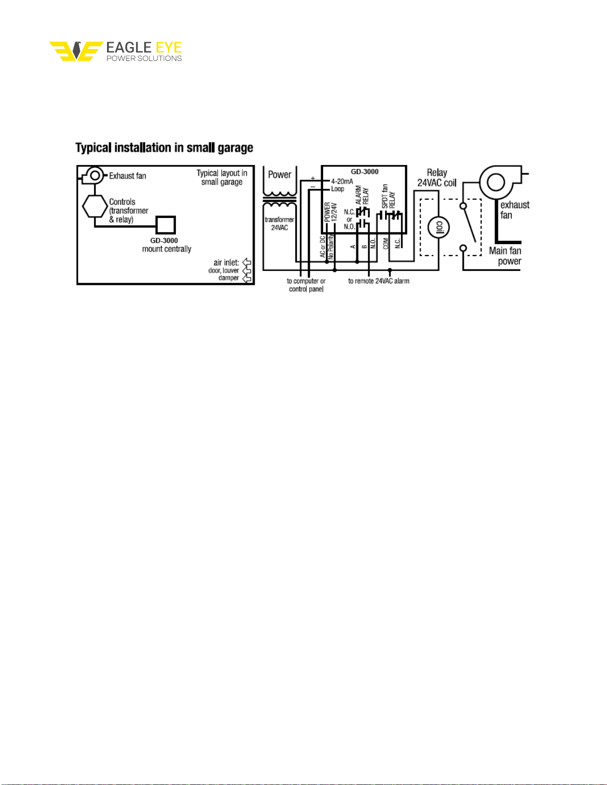
• The GD-3000 Combustible Gas Detector mounts on a standard 4x4 electrical box and
becomes cover for the box
• Supervised system: any internal detector problem will cause the fan & alarm relay to
activate
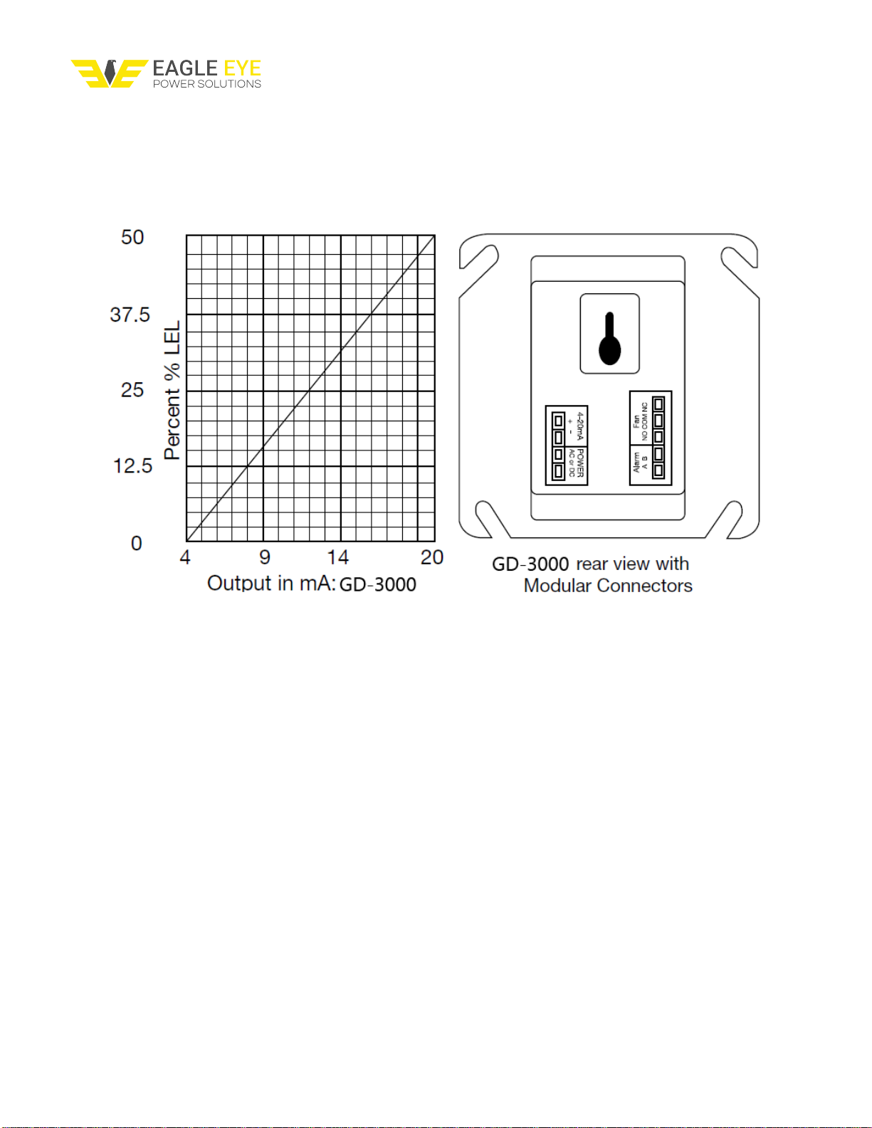
• Optional calibration kit is available. One screw allows access for calibration
2.4 Specifications
• Power: 3W (max) from 12 to 24VAC (Volts Alternating Current) or 12 to 48VDC (Volts
Direct Current)
• Current @ 24VDC: 75mA in alarm (two relays), 50mA (fan relay only)
• Shipping Weight: 1 pound (0.45 kg)
• Size: 4 1/2 x 4 x 2 1/8 in. (11.4 x 10.2 x 5.4 cm)
• Color: dark gray
• Connections: plugs/terminals
• Mounting box: (not included) 4x4 electric
• Fan relay: 5A, 240VAC, pilot duty, SPDT
• Fan relay actuation: selectable at 1, 2, 3, 4, 5, 6, 7, 8, 9, 10 (default), 11, 12, 13, 14,
15, 16, 17, 18, 19, 20% LEL
• Fan Delay Settings of 0, 1, 3 (default), 5 and 10 minutes
• Fan Minimum Run Time settings are OFF (default), 3, 5, 10 or 15 minutes
• Alarm relay: 0.5A 200V, 10VA
• Alarm relay actuation: selectable N.O. default or N.C.
• Alarm relay settings: OFF, 5, 10, 15, 20 (default), 25% LEL
• Current loop, 4-20mA for 0-50% LEL
• Operating environ: 0°F to 125°F (-18°C to 52°C). 10 to 90% RH
3. INSTALLATION AND OPERATING INSTRUCTIONS
The following instructions are intended to serve as a guideline for the use of the Eagle
Eye GD-3000 Combustible Gas Detector, Controller and Transducer. It is not to be
considered all-inclusive, nor is it intended to replace the policy and procedures for each
facility.
WARNING
This detector monitors for the presence and concentration level of certain specified
airborne gases. Misuse may produce an inaccurate reading, which means that higher
6

Eagle Eye GD-3000 User Manual
levels of the gas being monitored may be present and could result in overexposure and
cause sickness or death.
If you have any doubts about the applicability of the equipment to your job situation,
consult an Industrial Hygienist.
3.1 General Information
The Eagle Eye GD-3000 Combustible Gas Detector helps combustible gas detection
and automatic exhaust fan control for automotive maintenance facilities, enclosed
parking garages, warehouses with forklifts, etc. The GD-3000 can be used with 12VDC
or 24VDC N.O. (fire/security) panels.
3.2 Location
The Eagle Eye GD-3000 Combustible Gas Detector is usually located in areas where
there is potential for gas leaks; where there are gas appliances, areas through which
gas pipes pass, where batteries are being stored or charged, etc. DO NOT mount the
GD-3000 Combustible Gas Detector in a corner. DO NOT mount the GD-3000
Combustible Gas Detector where the normal ambient temperature is below below 0°F
or exceeds 125°F (-18°C or above 52°C). If the target gas is lighter than air; natural gas
(Methane) or Hydrogen (H2), mount the GD-3000 Combustible Gas Detector high on a
wall about one foot down from the ceiling. If the target gas is heavier than air; propane
(LP), mount the GD-3000 Combustible Gas Detector on a wall or column one foot
above the floor. Use the same spacing as for smoke detectors-30 foot centers, 900
square feet per detector.
Note: alcohols, ammonia, cleaning solvents, paint thinner; gasoline vapors and aerosol
propellants (aerosol cans such as hair spray usually contain a combustible gas) may
cause alarms.
3.3 Installation
1. The Eagle Eye GD-3000 Combustible Gas Detector mounts on a type 4S electrical
box supplied by the contractor.
2. Connect the Eagle Eye GD-3000 Combustible Gas Detector to Class 2 power supply
only. It is suggested to use a separate transformer for powering the unit or units
because of possible interferences from other devices on the same power supply.
7

Eagle Eye GD-3000 User Manual
3. Connect the Eagle Eye GD-3000 Combustible Gas Detector to the control cables with
terminal plugs. When making connections, make sure the power is off.
4. There are two terminals for Power: 12 to 24VAC or 12 to 48VDC, with no polarity
preference.
5. There are two terminals for the dry alarm relay contacts, again with no polarity
preference. The alarm relay can switch up to 0.5A, 200V, or 10VA. The alarm relay is
activated if gas reaches or exceeds the alarm settings.
6. The alarm relay can be configured to normally open (default) (N.O.) or normally
closed (N.C.) and will activate if the gas concentration exceeds alarm set point (5, 10,
15, 20 (default), 25% LEL). It will deactivate once the gas concentration drops below the
alarm set point. Note that the “disable” setting will cause the alarm relay not to engage
at all.
7. The dry contact, SPDT fan relay has three terminals. The common (COM.), normally
open (N.O.) and the normally closed (N.C.) contact. The fan relay can switch up to 5.0A
up to 240VAC. (see OPERATION section of these User Instructions for details on relay
settings).
8. The fan relay can be wired to normally open (N.O.) or normally closed (N.C.) and will
engage if the fan setting (1, 2, 3, 4, 5, 6, 7, 8, 9, 10 (default), 11, 12, 13, 14, 15, 16, 17,
18, 19, 20% LEL) is exceeded for the fan relay delay time (0, 1, 3 (default), 5, 10
minutes). The fan relay will disengage once both of these conditions have been met: 1.
Combustible gas concentration has dropped below fan setting and 2. Fan relay run time
(0 (default), 3, 5, 10, 15 minutes) has been exceeded. Note that the “disable” fan setting
will cause the fan relay to not engage. The fan relay will engage in troublefault condition
and will disengage once troublefault condition is cleared.
8

Eagle Eye GD-3000 User Manual
9. The Current Loop is 4mA in clean air and 4-20mA for 0-50% LEL.
Typical Multiple GD-3000 Combustible Gas Detector Installation
INSTALLATION NOTES
1. One sensor per 900 square feet (approximately).
2. If the gas used is natural gas (methane) or Hydrogen (H2) mount the Eagle Eye
GD-3000 Combustible Gas Detector high on a wall about one foot down
from the ceiling. If the gas used is propane (LP), mount the GD-3000
Combustible Gas Detector on a wall or column one foot above the floor.
3. See applicable building code for fan size vs air changes per periods of time.
4. Make sure there are air inlets to provide adequate air flow throughout the building.
5. Eagle Eye GD-3000 Combustible Gas Detector fan relays are dry contact & can
switch up to 240V.
6. Several fan relays (starters) may be used. Match the relays to the fan size.
9

Eagle Eye GD-3000 User Manual
Typical Connection to Alarm Control Panel
1. Eagle Eye GD-3000 Combustible Gas Detector can be used with 12VDC or 24VDC
N.O.(fire) panels.
2. Alarm panel provides battery backed up power to Eagle Eye GD-3000 Combustible
Gas Detector.
3. Eagle Eye GD-3000 Combustible Gas Detector dry contact fan relay can use panel
power or fan power. Check ratings on panel & fan.
4. Match fan relay contacts to fan size, and coil voltage to power source.
5. Alarm Control Panels are available with many features & can control other devices
such as smoke detectors, fire detectors & burglar alarms.
10

Eagle Eye GD-3000 User Manual
3.4 Power Up
WARNING
Each time the unit is turned on it performs a self-test, which activates visual alarms. If
the self-test fails, or if all the alarms do not activate, do not use. Failure to do so may
adversely affect product performance and result in sickness or death.
The Eagle Eye GD-3000 Combustible Gas Detector cycles through an internal self-test
cycle for the first minute that it is powered. The unit will execute the test cycle any time
power is dropped and reapplied (i.e. power failure). During the self-test cycle the unit
will display the firmware version number, then count down from 60 to 0 and finally go
into normal operation. The fan and alarm relay will be activated for the power-up cycle
unless the “Power Up Test” (PUt) option is OFF. The indicator light (LED) will flash
green during the self-test cycle. At the end of the 1 minute cycle, the unit will take its
first sample of the air and the light will turn solid green.
WARNING
Do not cover or obstruct visual alarm LED. Doing so may adversely affect product
performance and result in sickness or death.
11

Eagle Eye GD-3000 User Manual
3.5 Operation
1. With the display function turned “On”, the Eagle Eye GD-3000 Combustible Gas
Detector will show the current concentration of gas % LEL or “0” (zero) in clean air.
When the gas concentration reaches the Fan Relay setting (10% LEL, for example) the
display will flash back and forth between “FAn” and “10”. With the display function
turned ”Off”, the display does not show the gas concentration, but will show “FAn” as
long as the fan relay is activated.
2. With the display function turned “On” and the gas concentration reaching the alarm
relay setting, (20% LEL, for example) the display will flash back and forth between “ALr”
and “20”. The buzzer will sound indicating “Alarm” if the buzzer is turned “On”. With the
display function turned off the display does not show the gas concentration, but will
show “ALr” when the Alarm relay is activated.
3. With the 4-20mA function turned “On”, the 4-20mA output will correspond to the
concentration (0-50% LEL). The display will show “FAn” and “ALr” and sound as
outlined above.
3.6 Default Configuration – Factory Settings
• The default Display setting is Off
• The default Power Up Test setting is On
• The default Buzzer setting is Off
• The default Alarm Relay setting is activation at 20% LEL
• The default Fan Relay Delay setting is 3 minutes
• The default Fan Minimum Runtime setting is OFF
• The default Fan Relay setting is activation at 10% LEL
• The default Alarm Relay Configuration is Normally Open
• The default 4-20mA Output setting is OFF
To change settings, remove the Philips screw on the front of the Eagle Eye GD-3000
Combustible Gas Detector. Pull off the front cover of the unit.
Gas Selection
To select the Gas Option, in normal mode, press the Next button once to display the
current gas selection (mE is Methane, Pro is Propane and Hy is Hydrogen). Then
press the Enter button twice to enter the selection menu. The currently selected gas will
be shown on the display. Press Next to scroll through the available gases selections.
The selected gas will be flashing, press Enter to select the gas and Enter again to
confirm the selection. To return back to normal mode press Next until “End” is displayed
and press Enter.
12

Eagle Eye GD-3000 User Manual
Selecting Default Configuration – “dEF”
To select the Default Configuration, in normal mode, press the Next button twice to get
to “Con” or the Configuration menu.Then press the Enter button to enter the Con menu.
The first selection is the “dEF” or Default setting. Press Enter. If it is already in Default
configuration, there will be no action. If it is not already in Default configuration, “nO” will
be displayed. Press Next to change it to “YES” (flashing) then press Enter to confirm
the change (solid) and press Enter again to return to “dEF” in the Con menu. Press
Next until “End” is displayed then press Enter to return to normal operation.
Selecting Power Up Test Option – “PUt”
To select the Power Up Test Configuration, in normal mode, press the Next button
twice to get to “Con” or the Configuration menu. Then press the Enter button to enter
the Con menu. Then press the Next button to get to the second selection “PUt” or
Power Up Test setting. Press Enter. If the test is “On” press Next to turn it “OFF”
(flashing) then press Enter to confirm the change (solid) and press Enter again to
return to “PUt” in the Con menu. Press Next until “End” is displayed then press Enter to
return to normal operation.
Selecting Display Option – “dSP”
To select the Display Configuration, in normal mode, press the Next button twice to get
to “Con” or the Configuration menu.Then press the Enter button to enter the Con menu.
Then press the Next button twice to get to the third selection “dSP” or Display setting.
Press Enter. If the display is “On” press Next to turn it “OFF” (flashing) then press
Enter to confirm the change(solid) and press Enter again to return to “dSP” in the Con
menu. Press Next until “End” is displayed then press Enter to return to normal
operation.
Selecting Buzzer Option – “bUZ”
To select the Buzzer Configuration, in normal mode, press the Next button twice to get
to “Con” or the Configuration menu. Then press the Enter button to enter the Con
menu. The fourth selection is the “bUZ” or Buzzer setting. Press Next three times to
get to “bUZ” then press Enter. If the display is “On” press Next to turn it “OFF” (flashing)
then press Enter to confirm the change (solid) and press Enter again to return to “bUZ”
in the Con menu. Press Next until “End” is displayed then press Enter to return to
normal operation.
Selecting Alarm Relay Setting – “ArS”
To select the Alarm Relay Setting, in normal mode, press the Next button twice to get to
“Con” or the Configuration menu. Then press the Enter button to enter the Con menu.
13

Eagle Eye GD-3000 User Manual
The fifth selection is the “ArS” or Alarm Relay Setting. Press Next four times to get to
“ArS” then press Enter. If the display is “OFF” (disabled) press Next to change it to 5,
10, 15, 20 or 25% LEL (flashing) then press Enter to confirm the change (solid) and
press Enter again to return to “ArS” in the Con menu. Press Next until “End” is
displayed then press Enter to return to normal operation.
Selecting Alarm Relay Configuration – “Arc”
To select the Alarm Relay Configuration, in normal mode, press the Next button twice
to get to “Con” or the Configuration menu. Then press the Enter button to enter the Con
menu. The sixth selection is the “Arc” or Alarm Relay Configuration. Press Next five
times to get to “Arc” then press Enter. If the relay is “nO” (normally open) press Next to
turn it to “nC” (flashing) then press Enter to confirm the change (solid) and press Enter
again to return to “Arc” in the Con menu. Press Next until “End” is displayed then press
Enter to return to normal operation
.
Selecting Fan Relay Settings – “FrS”
To select the Fan Relay setting, in normal mode, press the Next button twice to get to
“Con” or the Configuration menu. Then press the Enter button to enter the Con menu.
The seventh selection is the “FrS” or Fan Relay setting. Press Next six times to get to
“FrS” then press Enter. If the fan relay is “OFF” (disabled) press Next to change it to 1,
2, 3, 4, 5, 6, 7, 8, 9, 10, 11, 12, 13, 14, 15, 16, 17, 18, 19 or 20% LEL (flashing) then
press Enter to confirm the change (solid) and press Enter again to return to “run” in the
Con menu. Press Next until “End” is displayed then press Enter to return to normal
operation.
Selecting Fan Relay Delay – “FrD”
To select the Fan Relay Delay setting, in normal mode, press the Next button twice to
get to “Con” or the Configuration menu. Then press the Enter button to enter the Con
menu. The eighth selection is the “FrD” or Fan Relay Delay. Press Next seven times
to get to “FrD” then press Enter. If the delay is “OFF” (disabled) press Next to change it
to 1, 3, 5, or 10 minutes (flashing) then press Enter to confirm the change (solid) and
press Enter again to return to “FrD” in the Con menu. Press Next
until “End” is displayed then press Enter to return to normal operation.
Selecting Fan Minimum Run Time – “Frr”
To select the Fan Minimum Runtime setting, in normal mode, press the Next button
twice to get to “Con” or the Configuration menu. Then press the Enter button to enter
the Con menu. The ninth selection is the “Frr” or Fan Minimum Run Time. Press Next
eight times to get to “Frr” then press Enter. If the runtime is “OFF” (disabled) press Next
to change it to 3, 5, 10 or 15 minutes (flashing) then press Enter to confirm the change
14

Eagle Eye GD-3000 User Manual
(solid) and press Enter again to return to “run” in the Con menu. Press Next until “End”
is displayed then press Enter to return to normal operation.
Selecting 4-20mA Output Option – “420” To select the 4-20mA Output Option, in
normal mode, press the Next button twice to get to “Con” or the Configuration menu.
Then press the Enter button to enter the Con menu. The tenth selection is the “420” or
4-20mA Output Option. Press Next nine times to get to “420” then press Enter. If the 4-
20mA is “On” press Next to turn it to “OFF” (flashing) then press Enter to confirm the
change (solid) and press Enter again to return to “420” in the Con menu. Press Next
until “End” is displayed then press Enter to return to normal operation.
3.7 Onboard Diagnostics
The Eagle Eye GD-3000 Combustible Gas Detector monitors all critical functions of the
unit through software diagnostics that continuously test and verify unit operations. If a
problem is found, the unit will switch to a fail-safe/error mode or trouble condition. In this
error mode, the Fan and Alarm relays will be activated; the 4-20mA current loop will go
to 24mA and the LED light will Flash Green. This is a safety precaution. To clear this
mode, simply turn off power to the unit for a few seconds, or
press the TEST switch (inside the unit). This will cause the unit to restart the 1 minute
self-test cycle.
The 4-20mA signal can be used for troubleshooting:
• 0mA is most likely a connection problem
• 4-20mA is normal gas reading range (0-50% LEL)
• 24mA indicates a Trouble condition
Error Codes
• t01 Sensor is missing
• t02 Temperature compensation failed
• t04 Bad EEPROM checksum
• t08 Sensor is shorted
• t10 Bad EEPROM
• t20 Bad factory calibration
• t40 Factory calibration was not done
• t80 SDADC reading failed
If the error mode repeats frequently, check for continuous power and proper voltage. If
power is not the problem and a unit has repeating error conditions, it may need to be
returned to Eagle Eye for service, as noted in these User Instructions.
15

Eagle Eye GD-3000 User Manual
3.8 Sensor Poisons
The gas sensor in the detector is designed with extreme sensitivity to the environment.
As a result, the sensing function may be deteriorated if it is exposed to a direct spray
from aerosols such as paints, silicone vapors, etc., or to a high density of corrosive
gases (such as hydrogen sulfide, sulfur dioxide) for an extended period of time.
4. MAINTENANCE
The Eagle Eye GD-3000 Combustible Gas Detector does not require regular
maintenance other than cleaning. The unit uses a long life pellistor sensor that has a 5+
year life expectancy.
WARNING
Do not disassemble unit or attempt to repair or modify any component of this
instrument. This instrument contains no user serviceable parts, and substitution of
components may impair intrinsic safety, which may adversely affect product
performance and result in sickness or death.
CAUTION
• Avoid the use of harsh cleaning materials, abrasives and other organic solvents. Such
materials may permanently scratch the surfaces and damage the display window,
labels, or instrument housing.
4.1 Cleaning
Cleaning of the external surfaces is best carried out using a damp cloth with a mild
detergent or soap. Vacuum under the cover with soft brush to remove dust or
contamination.
4.2 Testing
Using a certified gas with a concentration other than the one listed for this instrument
and sensor when conducting a calibration or calibration verification test (bump test) will
produce inaccurate readings. This means that higher levels of the gas being monitored
may be present and could result in overexposure and cause sickness or death.
General
16

Eagle Eye GD-3000 User Manual
There are multiple ways to test the Eagle Eye GD-3000 Combustible Gas Detector after
installation: Operation Test, Manual Operation Test, Combustible Gas Test and Quick
Gas Test. The GD-3000 Combustible Gas Detector also has the ability to test itself
automatically and does so every 2 1/2 minute cycle. If the unit detects an improper
voltage or inoperable component it will default into Error mode. In Error mode, the unit
will Flash Green and both the fan & alarm relay will be actuated. Check that the GD-
3000 Combustible Gas Detector OPERATING LED type light is illuminated,
continuously. If not, do not proceed with the tests. If the unit is in error mode contact
your local representative Eagle Eye technical support.
4.2.1 Operation Test
1. Remove the single screw in the middle of the front cover of the Eagle Eye GD-3000
Combustible Gas Detector.
2. Remove the front cover.
3. Observe the LED light on the front of the Eagle Eye GD-3000 Combustible Gas
Detector.
4. If the light is solid green proceed to step 6.
5. If the light is off or flashing Green, refer to the General section of this User Instruction.
6. Locate the switch labeled ENTER/TEST on the left side of the printed circuit board.
Press the Test switch once.
7. The Eagle Eye GD-3000 Combustible Gas Detector will step through a cycle test:
a. The display progresses through the Art (alarm relay test), Frt (fan relay test) then 42t
(4-20mA output test).
b. During the first 5 seconds of the test cycle, the alarm relay will be closed, so any
devices connected to that relay will be tested.
c. The Fan relay will be activated for the next 1 minute of the test, so if the fan circuits
are wired in the normal manner,
the fan should run.
d. The 4-20mA output will then ramp up from 4 to 20mA over the next 130 seconds of
the test, so if the circuit is wired
in the normal manner, the control panel or building automation system should respond.
e. At the end of the test cycle, the light will turn green and be on steady (Normal
Operation), the fan & alarm relay will be
in standby mode and the 4-20mA output will return to 4mA (in clean air).
8. When testing is completed reassemble the unit or units.
4.2.2 Manual Operation Test
This option gives the user the opportunity to manually initiate an individual test for each
relay, the analog output and the sensor response to gas. From normal operation mode
17

Eagle Eye GD-3000 User Manual
press the Next button 3 times to get to the Test Mode (tSt). Press the Enter button once
to get into the Test Menu. Press the Next button to scroll through the four test options
and press Enter to initiate the selected test. Note that if the relay or 4–20mA output has
been disabled, the test selection will not be displayed in the test menu.
Art - Alarm Relay Test, 10 seconds
Frt - Fan Relay Test, 60 seconds
42t - 420 loop test, 25 seconds
gtS - Gas Test, 3 minutes (no output to the panel during the gas test)
The display will flash during the test or in the case of the gas test the level will alternate
with the expected gas (mE, Pro or Hy).Once the test is complete, the display will return
to steady display. To exit the test menu, press the Next button until “End” is displayed
then press Enter to return to normal mode.
4.2.3 Combustible Gas Test
The following steps must be performed when conducting a calibration or calibration
verification test (bump test) to ensure proper performance of the monitor. Failure to do
so may adversely affect product performance and result in sickness or death.
• When performing a calibration or calibration verification test (bump test) only use
certified calibration gas at the required concentration level. Do not calibrate with expired
calibration gas.
• If the instrument cannot be calibrated, do not use until the reason can be determined
and corrected.
• Do not cover or obstruct display, audible alarm opening or visual alarm cover.
• Ensure sensor inlet is unobstructed and is free of debris.
General
The Eagle Eye GD-3000 Combustible Gas Detector can be bump-tested or calibrated
with a Field Calibration Kit (FCK) with Methane, Propane or Hydrogen gas, regulator
and test hood, available through your local representative or from Eagle Eye.
FCK Information
Several detectors can be calibrated with one FCK. The only limitation is the amount of
gas in the cylinder. The 17 liter cylinder with 0.2 LPM (Liters Per Minute) regulator has
approximately 85 minutes of continuous calibration run time. Replacement cylinders are
18

Eagle Eye GD-3000 User Manual
available. The gas cylinder should be replaced when the pressure gauge on the
regulator shows 25psi or less.
Note: For optimum test results it is suggested that the unit be in clean air (solid
green light on) and be in a low ambient air flow.
Gas Testing
Testing the Fan Relay
Note: The gas concentration to activate the fan relay depends on the setting.
1. Remove the Philips screw on the front of the Eagle Eye GD-3000 Combustible Gas
Detector. Remove the front cover.
2. Connect the 10% LEL cylinder of Combustible Gas to the regulator. Ensure that the
gas used for calibration matches thegas selected in the Eagle Eye GD-3000
Combustible Gas Detector configuration.
3. Assemble regulator, hose and test hood and place the test hood over the gas sensor.
4. Check the pressure gauge on the regulator. If you have 25psi or less you will need to
replace the gas canister.
Note: The time to activate the fan relay depends on the delay setting.
5. Turn on the regulator to start the gas flow and wait with the gas applied continuously.
6. With the display function turned “On”, the Eagle Eye GD-3000 Combustible Gas
Detector will show the current concentration of gas or “0” (zero) in clean air. When the
gas concentration reaches the fan relay setting (5% LEL, for example) the display will
19

Eagle Eye GD-3000 User Manual
flash back and forth between “FAn” and “5”. With the display function turned ”Off”, the
display does not show the gas concentration, but will show “FAn” as long as the fan
relay is activated
Note: If the Fan relay does not close within 2 minutes, consider these
possibilities:
a. Gas cylinder is empty, check the pressure gauge. Replace the gas cylinder if 25psi or
less.
b. Unit needs to be re-calibrated (go through recalibration and re-test).
c. Detector is in need of servicing (return unit to factory for servicing).
d. Detector has fan relay set to disable (OFF) or 20% LEL. Set fan relay to 5% LEL and
repeat the test.
7. Remove the gas from the sensor. Proceed to test the alarm relay or replace the top
cover.
Testing the Alarm Relay
Note: The gas concentration to activate the Alarm relay depends on the setting.
Connect the 20% LEL cylinder of Combustible Gas to the regulator. Ensure that the gas
used for calibration matches the gas selected in the Eagle Eye GD-3000 Combustible
Gas Detector configuration.
1. Check the pressure gauge. If there is 25psi or less the cylinder should be replaced.
2. Place the test hood over the gas sensor. Turn on the regulator to start the gas flow.
3. The Fan relay should activate according to the settings.
4. With the display function turned “On” and the gas concentration reaching the Alarm
Relay setting, (20% LEL, for example) the display will flash back and forth between
“ALr” and “20”. The buzzer will sound indicating “Alarm” if the buzzer is turned “On”.
With the display function turned off the display does not show the gas concentration, but
will show “ALr” when the Alarm relay is activated.
5. Note: If the Alarm relay fails to operate within 2 minutes, consider these
possibilities:
a. Gas cylinder is empty, check the pressure gauge. Replace the gas cylinder if 25psi or
less.
b. Unit needs to be re-calibrated (go through recalibration and re-test).
c. Detector is in need of servicing (return unit to factory for servicing).
d. Detector has Alarm relay set to disable (OFF). Set Alarm relay to 20% LEL and
repeat the test.
6. Remove the gas from the sensor after test. Proceed to test the 4-20mA output or
replace the top cover.
20
Table of contents
Popular Gas Detector manuals by other brands

AVE
AVE Domusair RG1/CO2 quick start guide

FORENSICS DETECTORS
FORENSICS DETECTORS FD-VAPE-WALL user manual

Bacharach
Bacharach IAM-100 Installation and operation manual

Adicos
Adicos GSME-X20 Supplementary instructions manual

Atest Gaz
Atest Gaz Teta Gas Guide book

Riken Keiki
Riken Keiki 70D Series Communication Function Manual