Simultalk 24G Wireless Features
1 www.eartec.com.com
Full duplex, two-way transceiver
Simultaneous tal - hands free communications
State of the art 2.4GHz digital technology
Certified for worldwide use
No license required
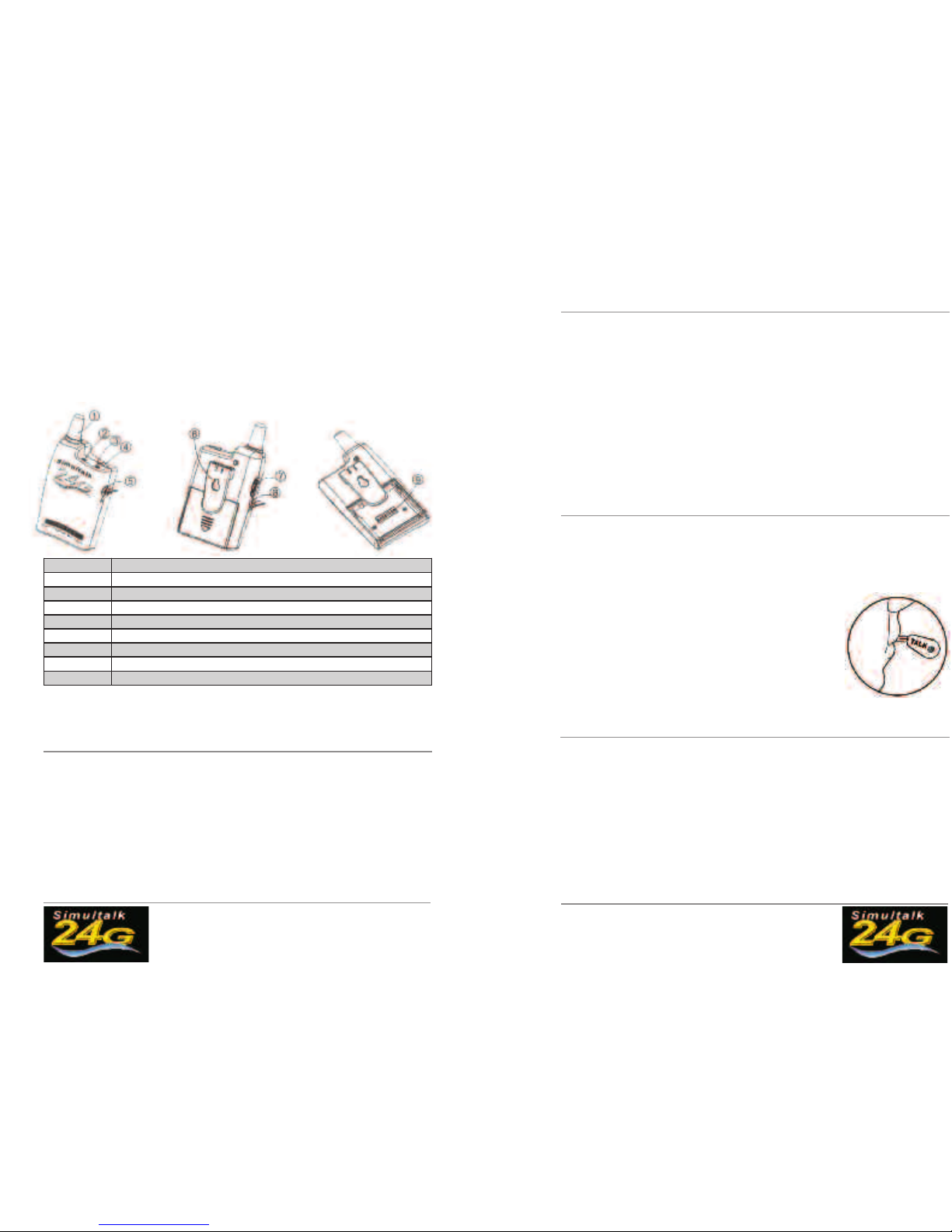
1 Antenna
2 Power ON Indicator
3 Status Indicator
4 Talk Button
5 Headset Socket
6 Belt Clip
7 ON/OFF Volume Control Knob
8 Charger Socket
9 Radio Channel Dip Switch - inside battery compartment
Simultalk 24G Wireless Instructions
Charging the Radios
The batteries that provide power to your system do not need to be “drained”. Simply follow
the procedure below within 48 hours before each use:
1. All radios should be OFF.
2. Plug AC Charger/Adapter into a wall outlet and attach to Radio Charging Jack.
3. Charge each radio for 10-12 hours.
4. The transceiver battery charges fully in 10-12 hours. To prevent overheating of the
charger and to prevent damage to the charge circuit do not leave the charger plugged in for
more than 12 hours. A fully charged battery will operate in full duplex up to 4.5 hours and
up to 8 hours switching to standby mode periodically.
Simultalk 24G Wireless Instructions (cont.)
www.eartec.com 2
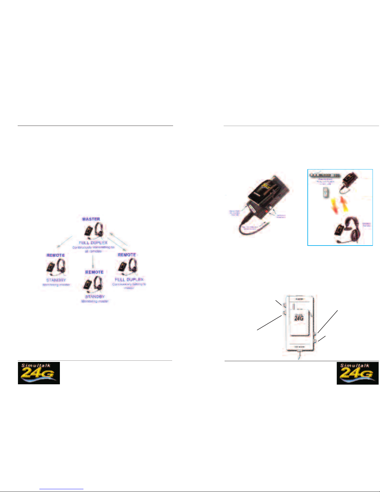
Identify our Radios
1. MASTER radio will be programmed to CONTINUOUS TALK.
-Press talk button to power ON radio
-Left light: red indicates power ON
-Right light: green indicates transmit only, receiver muted
-Right light: amber indicates transmitting and receiving
2. REMOTE radios will be programmed to CONTINUOUS RECEIVE.
-Press TALK button to power ON radio
-Left light: red indicates power ON
-Right light: red indicates receive only, mic muted
-Right light: amber indicates transmitting and receiving
Using our Radios
1. Charge radios as indicated above.
2. Plug headset jack into headset socket. Turn the volume ON. Position headset micro-
phone directly in front of mouth.
IMPORTANT NOTE: Eartec headsets include a special noise cancelling microphone that provides
digital voice translation. For optimum performance adjust microphone
boom so the element is directly in front of, and approximately 1 inch
from the user’s mouth.
NOTE: To communicate properly, all radios in the group must be set to the same frequency. The dip
switch channel programming feature is located inside the battery compartment. See page 5 for channel
combinations.
Simultalk 24G Wireless System Setup
For Systems with 2 Radios
1. Charge radios as indicated.
2. Identify MASTER radio, and turn it on.
3. Set MASTER radio to transmit by pressing the talk button once, and confirm amber LED
light.
4. Turn on REMOTE radio. LED light should be red, indicating standby mode.
5. Set REMOTE radio by pressing the talk button once,
and confirm amber LED light.
6. ou are ready to communicate.