Earth Way S25 SPRAY-PRO User manual

Rotate wheel
to help
install pins
Steel Ring
Flat Washer
Slide one knurled pin into each slot
in the hub and then spray with WD-40
or a light oil and slide wheel in fully and
secure with a cotter pin
1” Cotter Pin
Coast Wheel
Drive Wheel
1” Cotter Pin
S25
SPRAY-PRO PUSH SPRAYER
ASSEMBLY and OPERATING INSTRUCTIONS
SPRAY-PRO
SPRAY-PRO
EarthWay
R
EarthWay
R
S
L
I
D
E
Lower
Handle
Axle Bushing
Congratulations on the purchase of this new sprayer from Earthway Products, Inc. Please call us if you have any difculty
with assembly or operation of this sprayer. We can be reached via the telephone at 800-294-0671 or 574-848-7491, Monday
- Friday 9:00am ~ 4:00pm or visit us online at www.earthway.com This sprayer comes with lifetime technical support,
email us at techsupport@earthway.com.
HELPFUL HINTS: READ THE DIRECTIONS BEFORE ASSEMBLY
THIS SPRAYER COMES PARTIALLY ASSEMBLED, REQUIRING YOU TO INSTALL THE WHEELS, HANDLE ASSEMBLY,
SPRAY GUN HOLDER, AND CONTROL ROD. IT SHOULD TAKE APPROXIMATELY 15 MINUTES WITH THE USE OF TWO
7/16” WRENCHES AND 1 PAIR OF PLIERS.
5Your sprayer is designed to be pushed at three miles per hour, which is a brisk walking speed. Slower or faster speeds
will change the spray patterns and output volumes that you will achieve.
5Clean your sprayer tank thoroughly after each use. Wash with clean water and push sprayer several feet to evacuate any
residual materials until you see clean water. Do this in a safe area as described in the chemical supplier directions.
5Gears are permanently lubricated at the factory. Do not open the gearbox or dirt may enter.
5Check all hose connections regularly to ensure they remain tight.
5If unit fails to spray on initial use, or leaks from the nozzle, remove the cap from the top of the DCV, wipe off the top of
DCV body to remove any debris, and then replace the cap and tighten.
5Coat all metal surfaces (inside & outside of chassis) with light oil or silicon spray to help prevent corrosion.
5When the tank is empty, PULL THE SPRAYER BACKWARD to the designated cleaning or storage area to prevent
damage that can occur with a dry pump.
2. Turn the S25 upside-down on to the tank.
3. Ensure that the Axle Bearings are pushed into the Axle Bushing on both sides as shown
at the right. Install the Coast wheel (this wheel does not have the steel ring on the inside
hub as shown below) on to axle using the cotter pin hole closest to edge of the axle.
Insert 1” cotter pin through the axle and bend with pliers to prevent pin from falling out.
Cotter Pin
Locations
1-2012 Pt. # 52230 PAGE 1
1. Open carton and remove the Handles, Control Rod, Hardware pack, Wheels, and the
S25 from carton.
4. Install the at washer onto the axle and slide to the lower
handle. Next, position the drive wheel onto the axle 2”
and install the three (3) knurled pins one into each slot
located between the hub and the axle as shown at the
right, coat the knurled pins with WD-40 or a light oil,
nish by sliding the wheel tight against the lower handle.
Now insert 1” cotter pin through axle, bend with pliers to
prevent cotter pin from falling out.
NOTE: Included is extra set of Knurled Pins (S25-30003)
which should be saved for future use. These are wear items
and will need to be replaced, and are available to purchase
directly through our Parts department.

8. Next, Install Control Rod into Valve Adapter by pressing onto
the Valve Adapter located at the back of the sprayer skirt, shown
below right. Install the Control Rod by installing attened end
of Control Rod into Valve Adapter, shown below right.
NOTE: Make sure that the ValVe Handle and
the Control rod Handle point in the SAME
DIRECTION.
Finally, install the Gun Holder onto the lowest bolt (closest
to the sprayer TANK) and secure with a 2” bolt and
locknut.
Be sure to position the Gun Holder as show above.
TIGHTEN NOW.
PAGE 2
Long End
holes farther
from one end Handle Shaft
12344
Handle
Spacer
32103
1/4-20 Lock Nut
31120
2” HHCS
5. Install handle shaft to lower handles as
shown. Using 2” bolts and locknuts.
Make sure that you install the
handle shaft with the long end
facing toward the sprayer.
TIGHTEN BOLTS AND NUTS NOW.
¼-20 x 2”
Hex Head Bolt
Handle
Spacer
Upper Handles
¼-20
Locknuts
POSITIONS
LOWER
UPPER
Handle Shaft
Spray Gun Holder
SPRAY TRANSPORT
VERY IMPORTANT
Control Rod Handle MUST point in the
same direction as the VALVE HANDLE
Nut Protector
6. NOTE: Before installing the Gun Holder and Upper Handles to the
Handle Shaft, the Upper Handles have (3) three positions for operators
comfort. If operator chooses the middle or upper positions, please use
the Handle Spacer. Install the Handle Spacer in hole nearest the handle
grips as shown to the right. Insert 2” bolt through Upper Handle, then
through Handle Spacer and then through other Upper Handle, then
secure loosely ¼-20 locknut. Now install one 2” bolt, so that it goes
through the top hole in the handle shaft and secure with ¼-20 locknut.
TIGHTEN BOLTS AND NUTS NOW.
7. Install Control Rod into the Gun Holder as shown below. Next install
black nut protector to the short leg on Control Rod.

PAGE 3
For Support for your S25, please contact:
nortH ameriCa europe
DMMP Limited
T: 0845 643 9776
W: www.earthway.co.uk
Muggioli Giardinaggio
T: 0422 96 9990
W: www.muggioligiardinaggio.com
Earthway Products, Inc.
P.O. Box 547
1009 Maple Street
Bristol, IN 46507
T: 574-848-7491
T: 800-294-0671
E: techsupport@earthway.com
W: www.earthway.com
EuroAmerica
T: +31 (035) 5315696
W: www.euroamerica.nl
5-YEAR LIMITED WARRANTY
Earthway Products, Inc. warrants this product free of defects in original workmanship and materials for a period
of 5-years to the end user with the original purchase receipt. If a manufacturing non-conformance is found,
Earthway Products, Inc. at its discretion will repair or replace the part(s) or product at no charge provided the
failure is not the result of incorrect installation, mishandling, misuse, tampering, or normal wear and tear as
determined by Earthway. Earthway at its discretion may require that the part(s) or product be returned along with
the original purchase receipt at owners’ expense for examination and compliance with the terms of this warranty.
Do not return any product without rst receiving authorization from Earthway Products, Inc. To seek remedy
under this warranty, contact Earthway Products, Inc. at 574-848-7491, techsupport@earthway.com or write to
Earthway Products, Inc. P.O. Box 547 Bristol, Indiana 46507 and describe the nature of the manufacturing defect.
SPECIFIC LIMITATIONS: This warranty covers only the part(s) or product; any labor charges associated
with repair or replacement of non-conformances are specically excluded. Due to the corrosive nature of most
fertilizers and ice melt products, Earthway Products, Inc. makes no warranty against and specically excludes
part(s) or product degradation or failure due to corrosion or its effects. Clean and dry your sprayer thoroughly
after each use, as a preventative measure, coat all metal parts (inside and outside of the tubing) with a light oil or
silicon spray.
4
3
2
1
NOZZLE
with
FLAT SIDES
align with
CAP Tabs
RUBBER
WASHER
CAP in ready to
install position
CAP in LOCKED
position
DCV Locking Tabs
CAP Tabs
Nozzle Installation
5To remove turn Cap from right to left
5Push Nozzle out of the Cap and remove rubber washer.
5Install Nozzle aligning the at sides with the Cap tabs and
reinstall rubber washer.
5To install the assembly, align the Cap slot with DCV locking
tabs and push onto DCV and turn left to right to lock.

How to use your S25 Sprayer
The S25 SPRAY-PRO sprayer is designed to be simple to use, easy on the operator and provide
years of accurate spraying. The S25 is the latest development from Earthway Products, Inc., a
world leaders in the manufacture of broadcast spreaders, seeding tools, and sprayers.
Calibration
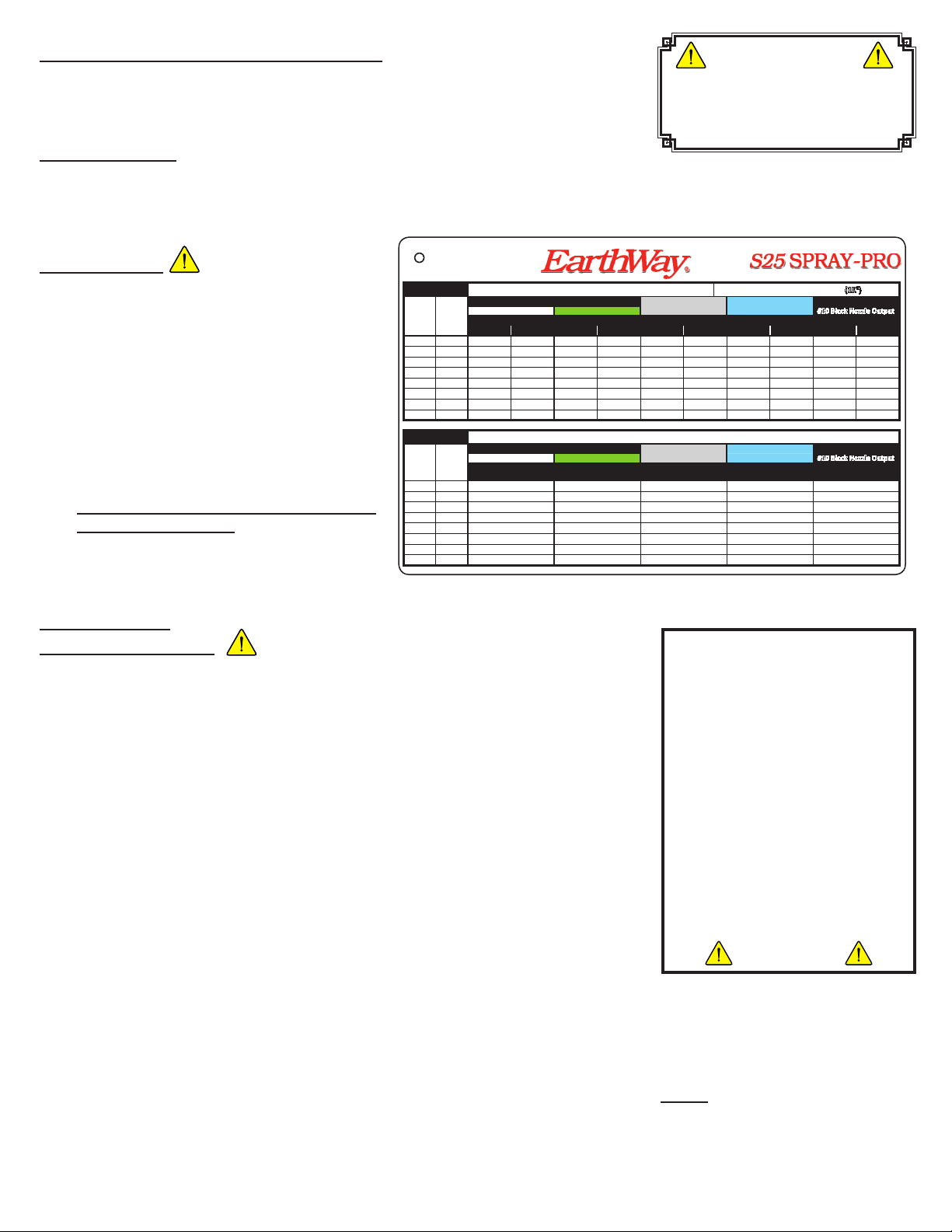
The S25 is supplied with three different nozzle options. The table below shows the characteristics and performance of the supplied nozzle
options at the eight different height setting of the DCV holder. Other Turbo Floodjet®are nozzles available from a TeeJet Dealer if
additional application rates are required. You can download a new Spray Rate Chart at www.earthway.com.
Before use
Before using any liquid products always read thoroughly
the manufacturers product label, to ensure correct
dosage and proper handling of the product being
applied through the applicator. Use the correct Safety
Equipment as directed by the chemical manufacturer.
;Check that the applicator has been thoroughly
cleaned from its previous use and that both the
nozzle outlet and the handgun line (if included)
have been washed through.
;Always spray on a day where wind is minimal.
It can be unsafe and inaccurate if spraying is
undertaken in windy conditions.
;Always wear appropriate safety clothing when
the sprayer is being used. Refer to manufacturers
instructions, or contact your supplier of the
product being applied for safety recommendations.
;Make sure the tires are properly inated to 20 psi.
How to use ~ Walk behind spraying
Practice before use
It is recommended for rst time users of the machine that the user familiarizes him/her self with
the workings of the sprayer. By simply putting water in the spray tank and spraying it out onto a
dry tarmac surface the operator will very quickly familiarize themselves with the workings of the
machine. Make sure the spray tank is then emptied of water before further use.
Make sure the handlebar is set right for the size of the operator. There are three position options
on the upper handle for different user heights. By having the handle in the correct position for
the individual user it will make pushing the machine simpler and make spray accuracy easier to
achieve.
;Choose the correct nozzle of the three nozzle options that is suitable for the product being
applied. (See calibration chart above)
;Ensure the Spray (ON) / Transport (OFF) lever on the handlebar is in the Transport position.
The Transport position is with the lever over to the right side when standing behind the
handlebars of the machine.
;Make sure the tank is clean and there is no chance of remnants or deposits from a previous
spray task being left in the tank.
;With the tank clean ll the tank with the required volume of liquid for the designated spray
task, making sure the product being used is mixed and being applied in accordance with the
manufacturers instructions.
;With the control lever is in the Transport (closed position) the machine can be safely pushed to the area where spraying is to be
carried out.
;Locate the sprayer at the point at which spraying needs to commence. Lift the machine up off the two feet, so the body of the
machine is parallel with the ground (important see drawing on next page). To spray simply roll the control lever (ON/OFF) over to
the left side (SPRAY POSITION), and walk forward at a brisk walking speed 2 to 3 MPH is recommended.
;To stop the spray roll the ON/OFF lever back to the right side (TRANSPORT POSITION). NOTE: When the Spray/Transport
lever is to the right side (TRANSPORT POSITION) and the machine is being pushed, the pump is pumping liquid out of the
tank and circulating it back into the tank. This circulation provides agitation and helps keep liquids that are mixed with water in
suspension while walking the sprayer to and from the area being treated.
DO NOT PUSH
FORWARD WITH
TANK EMPTY, PULL
BACKWARD
S25 Mark III Applica on Coverage - OUNCES/SQUARE FOOT OUNCES/1,000 SQUARE FEET (1K²)
Spray
width in
Inches
DCV
Se ng
Posi on
Height
OTHER Turbo Floodjet® Nozzles FINE SPRAY MEDIUM SPRAY COARSE SPRAY
#4 White Nozzle Output #7.5 Green Nozzle Output #3 Gray Nozzle Output #5 Blue Nozzle Output #10 Black Nozzle Output
SPRAY RATE SPRAY RATE SPRAY RATE SPRAY RATE SPRAY RATE
OZ/SQ FT OZ/1K² OZ/SQ FT OZ/1K² OZ/SQ FT OZ/1K² OZ/SQ FT OZ/1K² OZ/SQ FT OZ/1K²
60 1 0.10 97.7 0.11 113.6 0.07 72.7 0.11 105.3 0.12 115.2
58 1.5 0.10 101.1 0.12 117.6 0.08 75.2 0.11 108.9 0.12 119.1
54 2 0.11 108.6 0.13 126.3 0.08 80.8 0.12 117.0 0.13 127.9
50 2.5 0.12 117.3 0.14 136.4 0.09 87.3 0.13 126.4 0.14 138.2
44 3 0.13 133.3 0.15 155.0 0.10 99.2 0.14 143.6 0.16 157.0
43 3.5 0.14 136.4 0.16 158.6 0.10 101.5 0.15 146.9 0.16 160.7
39 4 0.15 150.4 0.17 174.8 0.11 111.9 0.16 162.0 0.18 177.2
36 4.5 0.16 162.9 0.19 189.4 0.12 121.2 0.18 175.5 0.19 191.9
S25 Mark III Applica on Coverage - GALLONS/1,000 SQUARE FEET
Spray
width in
Inches
DCV
Se ng
Posi on
Height
OTHER Turbo Floodjet® Nozzles FINE SPRAY MEDIUM SPRAY COARSE SPRAY
#4 White Nozzle Output #7.5 Green Nozzle Output #3 Gray Nozzle Output #5 Blue Nozzle Output #10 Black Nozzle Output
SPRAY RATE SPRAY RATE SPRAY RATE SPRAY RATE SPRAY RATE
GAL/1000 Square Feet GAL/1000 Square Feet GAL/1000 Square Feet GAL/1000 Square Feet GAL/1000 Square Feet
60 1 0.76 0.89 0.57 0.82 0.90
58 1.5 0.79 0.92 0.59 0.85 0.93
54 2 0.85 0.99 0.63 0.91 1.00
50 2.5 0.92 1.07 0.68 0.99 1.08
44 3 1.04 1.21 0.77 1.12 1.23
43 3.5 1.07 1.24 0.79 1.15 1.26
39 4 1.17 1.37 0.87 1.27 1.38
36 4.5 1.27 1.48 0.95 1.37 1.50
S25 Rate Card.indd 1 7/6/2011 12:22:35 PM
PAGE 4
For best results keep enough
liquid in the tank to ensure
the pump supply line remains
lled. Hills and rough
ground can create a “wave
effect” in the tank that will
cause the pump to have an
inconsistent spray or to lose
prime. If this occurs, turn the
control lever to TRANSPORT
and push a few feet to
re-establish the prime and
continue from where you
stopped.

How to use the S25 Sprayer - continued
When Tank is empty, pull the S25 backwards to prevent and damage to the pump.
Technical spray information and how to ensure accuracy
The S25 SPRAY-PRO Mark III has an adjustable height nozzle that offers a spray width
from approximately 3 feet/.9 meters to 5 feet / 1.5 meters.
Spray Width Adjustment
You can adjust the spray width of the S25, which will change the application coverage,
by moving the Adjustable DCV holder up or down. To use, loosen the knob located
on the front of the skirt, and slide the DCV & Nozzle assembly up/down to the desired
spray width or to a position indicated on the Application Chart on the previous page, then
tighten knob.
The SPRAY-PRO Teejet TF nozzles are designed to “feather” at the edges to allow the
second pass to “feather in,” and so provide uniform coverage. The area of “feather” or
overlap, is approximately 15% of the spray width at the edges, for a total of 30% over the
two edges/ends of the spray pattern. To maximize uniform coverage the second pass over the area
should allow for the 15% “feather” or overlap.
Ensure accuracy
It is important that the S25 SPRAY-PRO sprayer is pushed in a
manner that keeps the spray head parallel to the ground at all times, so that the spray
nozzle is constantly kept at the same correct height. Keeping the height of the nozzle
constantly parallel to the ground ensures the nozzle will spray to its stipulated spray
application cover. If the sprayer is pushed at a downward angle and the nozzle tip is
nearer to the ground, the spray width will be reduced and over application will occur. In
the reverse situation of the spray nozzle height being increased by pushing the sprayer at
an upward angle the nozzle fan will be wider, the spray width will becoming inaccurate,
under application will likely occur. To ensure spray width accuracy it is important that
the handlebar height is set right for the individual user, and the operator is aware that the
sprayer is pushed in a manner that keeps the nozzle constantly parallel with the ground.
Keeping the top of the tank parallel with the ground is a good guide.
To aid accuracy use a proprietary spray dye indicator which allows the operator
to see where they have sprayed. Contact your local landscape supplier for a
recommendation.
After use
1. Empty any unused contents out of the spray tank. The S25 SPRAY-PRO tank has been designed
to easily empty and clean. Dispose of the tank contents and all washings in accordance
with the manufacturer’s disposal instructions on the product that has been used.
2. Wash out the tank thoroughly using clean water and or a preparatory tank
cleaner. Make sure that the nozzle and spray gun (if included) are thoroughly
washed as well. To wash through the pipework to the spray nozzle, add
an additional 1/2 gallon or 2 liters of clean water to the tank and wash this
through the nozzle by pushing the sprayer over a safe area for the purpose of
disposal of washings.
3. Empty all water out of the sprayer making sure no water is left in the pump
over winter - do not allow to freeze, unless you have setup the S25 to operate
in freezing temperatures using an Ice Melt or snow pre-treatments.
Maintain the wheel knurled pins regularly by cleaning any debris or dirt
from the Drive Wheel axle area. Keep knurled pins well lubricated to
prevent seizure. An Extra set is included!
4
3
2
1
Liter Gallon
25
20
15
10
5
2
6
5
4
3
2
1
S25 SPRAY-PRO
S25 SPRAY-PRO
EarthWay
EarthWay
®
®
Spray width can change
if you lift or lower
the handle.
Position handle to keep
the nozzle parallel
with the surface.
4
3
2
1
25
20
15
10
5
2
6
5
4
3
2
1
SPRAY-PRO
S25
Earth
W
ay
R
G
RO
U
N
D
A
D
J
U
S
T
S
2
”
PAGE 5
Spray Pattern
FEATHERED-EDGE
1X RATE
PATH IS
ONE WAY
2X RATE
PATH IS
BOTH WAYS
FEATHERED-EDGE
Most applications will only require
one pass of up/back (1X Rate). When
higher application rates are required a
cross pattern (2X Rate) as shown above
should be used.

Liter Gallon
25
20
15
10
5
2
6
5
4
3
2
1
33108
3/16” x 1” Cotter pin
A
B
C
D
4
3
2
1
A
B
S25 SPRAY-PRO
S25 SPRAY-PRO
Earth
W
ay
R
S25-60000
Tank w/Cap
S25-41000
Control Rod
S25- 24507
Gun Holder
12344
Handle Spacer 60175
Upper Handles w/Grip
31120
2” HHCS
S25-24508
Control to Valve
Adapter
19132
Tube Plug
S25-30001
1” HHCS
25223
Handle Shaft
S25-44292
Frame Brace
32103
1/4-20 Lock Nut
31120
2” HHCS
31121
1-1/4” HHCS
31100
1-1/2” HHCS
25228
Cross brace
12152
Axle Bushing
12148
Axle Bearing
70138
Wheel
25222
Lower Handle
S25-24501
Gearcase & Axle Assembly
S25-60001
Skirt
S25-24506
DCV Mount 31120
2” HHCS
31165
1/2” HHCS
S25-24505
Pump Cover
S25-70000
DCV Nozzle
Adapter
S25-70003
Nozzle Holder w/gasket
S25-70001
3-way Valve
S25-70010
3-Way Valve
Retainer
&
31135
#8 x 1/2 Screw
S25-25722
Frame
S25-19003
Herbie Clamp
Nozzles
S25-70004 Black
S25-70006 Blue
S25-70012 Gray
S25-19002
Tee 1/4 NPT Male
to 3/8” barbed
S25-19001
90 deg Elbow
1/4 NPT Male to 3/8” barbed
34108
9/16" OD. X .257 ID.
Washer Zinc
70142
Nut Protector
S25-30004
Washer
S25-70138
Drive Wheel
32103
1/4-20 Lock Nut
32103
1/4-20 Lock Nut
S25-19105
3/8” Cap for Tee tting
31138
#8 x 3/8 Screw
Pump to Tank
Pump to 3-way
Valve
S25-24600
Pump
31138
#8 x 3/8 Screw
S25-70008
3.5” Drop-In
Tank Filter
S25-70011
Knob
Hoses
S25-19100 (A)
S25-19101 (B)
S25-19102 (C)
S25-19103 (D)
36501
1" Carriage Bolt
S25-60002
Kelch Cap
37107
#6-32 x 1" PHPS SS
33108
3/16” x 1” Cotter pin
S25-30003
Knurled Pins
EXTRA
S25-30003
Knurled Pins
S25-19004
Spray Gun
S25-19000
1/4 NPT Female
to 1/8” adapter
31120
2” HHCS
32103
1/4-20 Lock
Nut
S25-19003
Herbie Clamp
OPTIONAL
S25-77000 Spray Gun Kit
Earthway Products, Inc.
P.O. Box 547
Bristol, IN 46507
Phone: 800-294-0671
www.earthway.com
PAGE 6
S25
SPRAY-PRO Liquid Sprayer ~ Parts List
Table of contents
Other Earth Way Paint Sprayer manuals