East Tester ET5420 User manual

ET5420 double channel
Programmable DC power load
User manual
Hangzhou Zhongchuang Electron Co.,Ltd

Basic Information
ET54 series single/double channel programmable dc electronic load, USES the hi
gh performance chip, high speed, high precision design, provide 1mV、
1mA resolution,
superior performance, can be widely applied to the charger, switching power supply,
linear power supply, production test of all kinds of batteries and other industries, sci
entific research institutions such asthe test research and development.
Product features:
humanized design.
2.8-inch TFT LCD display, rich display content, support Chinese and English display;
Simple and convenient operation process, with intuitive interface display system, easy to use;
It has the function of key lock to prevent misoperation.
high-performance load:
The basic measurement modes of CC, CV, CR, CP, CC+CV, CR+CV are provided.
Provide professional battery test and LED test;
Dynamic test mode, can test the dynamic power output performance;
Scanning test mode can test the continuity of power output within a certain range.
List mode, which can simulate various loaded state changes;
Short circuit test for simulating load short circuit;
The measurement model of the far end can improve the measurement accuracy when the curr
ent is high.
Support external trigger input;
Built-in buzzer alarm;
Power off to maintain data storage function;
Remote operation can be carried out through RS-232 interface and USB Device interface.
With PS2 interface, support external keypad to set data values;
safety protection:
With over voltage, over current and overpower protection functions, over voltage and over current
parameters can be set flexibly to effectively protect the load.
It has the function of secondary over-temperature protection to realize the double over-temperature
protection of software and hardware.
It has the function of intelligent fan speed control, which can effectively reduce the working fan
noise.
With output polarity reverse protection;

General technical specifications:
Power voltage: 220Vac±10%, optional 110Vac±10%, 45-65hz
Display: 2.8-inch TFT LCD, resolution 320 x 240
Operating temperature: 0 ℃to 40 ℃
Storage temperature: - 10 ℃to 70 ℃
Relative humidity: < 80%
Interface: standard USB Device, RS232(or 485)
Size: 90mm * 190mm * 300mm (width * height * depth)
Standard accessories:
One three-core power cord
Two power fuses
1 user manual

Catalog
一、Quick Reference.......................................................................................................................... 1
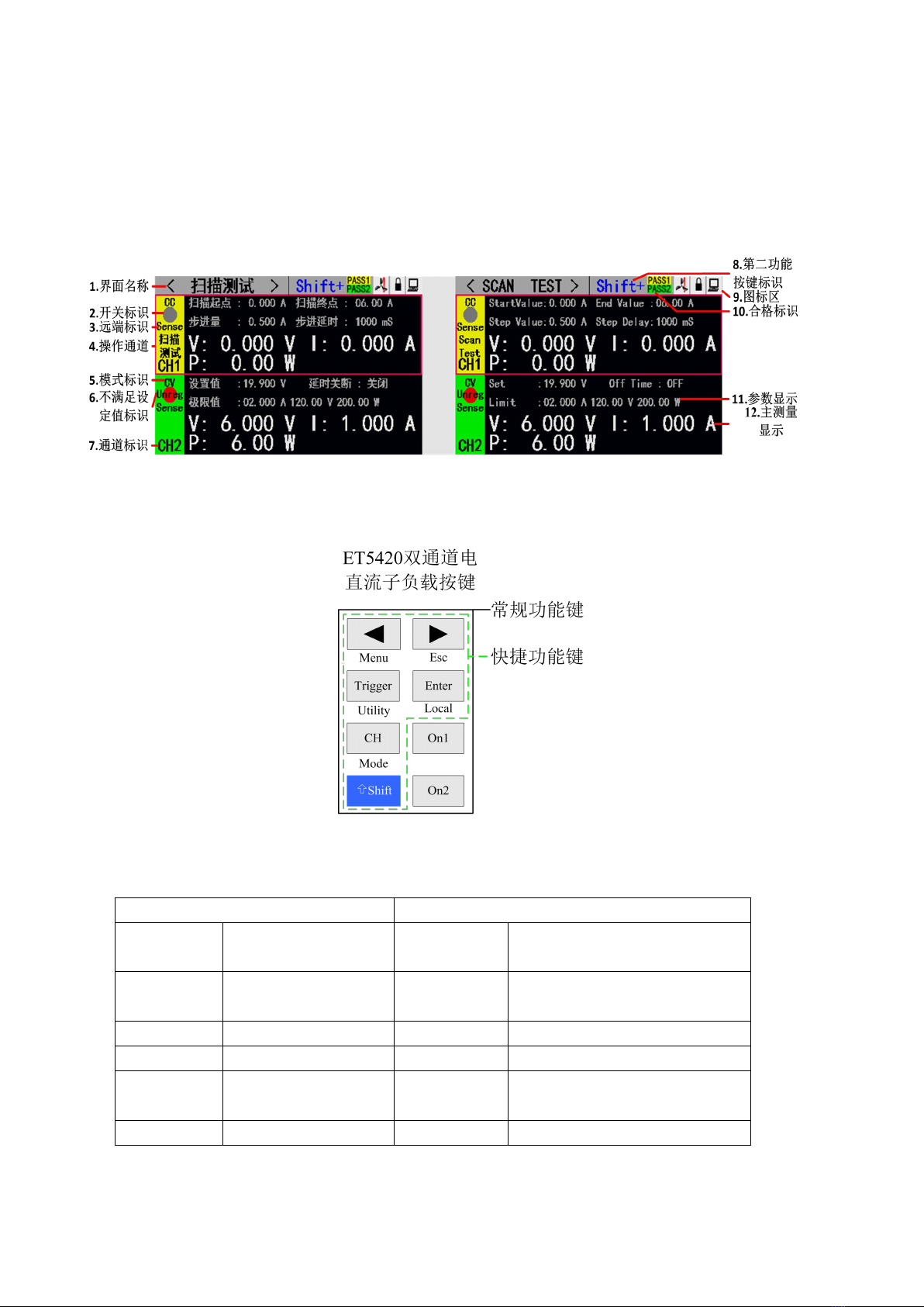
1.1 Front Panel Display ...............................................................................................................1
1.2Front Panel Press........................................................................................................................ 1
1.3Press Introduction .....................................................................................................................1
二、Function Operation ..................................................................................................................2
2.1 Remote/ Local Switch Opertion ............................................................................................2
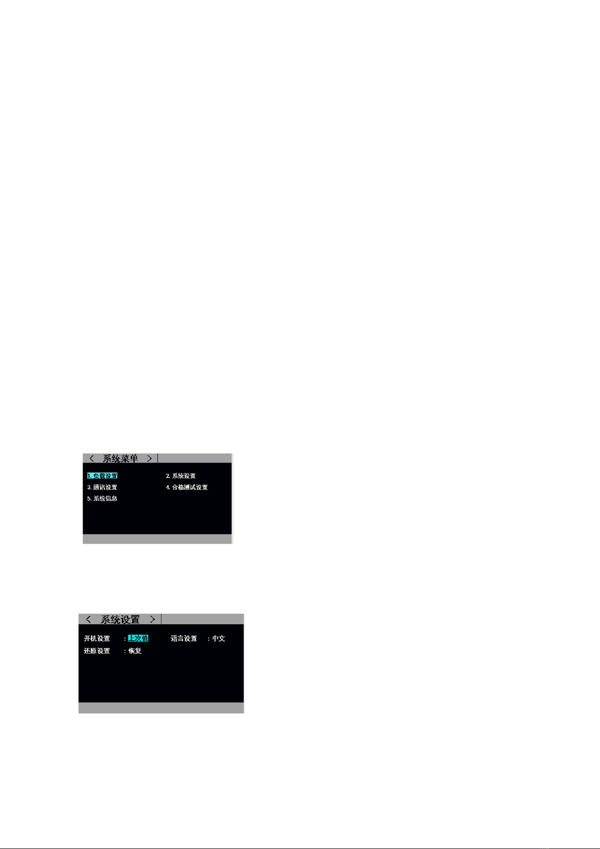
2.2 System Setting Operation..........................................................................................................2
2.3 Load Setting operation ............................................................................................................ 3
2.4 Basic Mode operation ..............................................................................................................3
2.4.1Constant Current Test Mode ............................................................................................. 3
2.4.2Constant Voltage Test Mode...............................................................................................4
2.4.3 Constant Resistance Test Mode......................................................................................... 5
2.4.4 Constant Power Test Mode .............................................................................................. 5
2.4.5 Constant Current Switch To Voltage Test Mode .............................................................6
2.4.6 Constant Resisitance Switch To Voltage Test Mode ...................................................... 6
2.5 Dynamic Mode Test Operation..............................................................................................7
2.6 Listing Mode Test Operation ............................................................................................... 9
2.7 Scanning Mode Test Operation ........................................................................................11
2.8 Battery Test Operation ....................................................................................................... 12
2.9 LED Test Operation ........................................................................................................... 13
2.10 Short Circuit Test Operation .......................................................................................... 15
2.11 Protection Function............................................................................................................... 15
2.12Triggle Function ...................................................................................................................15
2.13Qualified test operation.......................................................................................................... 16
2.14 Other system settings .......................................................................................................... 16
2.14.1 Key Lock Funtion .........................................................................................................16
2.14.2 Outer Interface Function................................................................................................ 17
四、 Technic Specification........................................................................ 错误!未定义书签。

一、Quick Reference
1.1 Front Panel
1.2Front Panel Press
1.3 Key Manual
General function key
Shortcut function key
CH
CH1/CH2 switching
Shift+Menu
Non-basic mode parameter
settings
On1、On2
CH1/CH2 switch
key
Shift+Esc
return
Trigger
Trigger key
Shift+Mode
Mode selection
Enter
Enter
Shift+Utility
System common settings
◀ ▶
Cursor left and right
keys
Shift+Local
Remote local switching
Shift
Shift overlay

二、Function Operation
Before testing the pending test source by load, In order to ensure the stable and safe
operation of the load, please be sure that after connecting the load and pending testing
source by the way of red positive and black negative, turn on power output firstly , then
turn on the load.
2.1 Remote/ Local Switch Operation
When the load is working under remote control operation mode, there will be a
corresponding icon showing in the top line of the interface, then interface is locked. This
action could be controlled and operated by the PC instruction . Also users can press the
button 【Shift】+【Enter 】simultaneously to switch to the Local operating mode.
2.2 System Setting Operation
Press [Shift] + [Trigger] (Utility) to enter the system menu interface as shown in Figure 2.2.1.
Rotate the knob to select and enter the corresponding submenu. In the system setting
interface, you can complete operations such as language, factory reset, power-on settings, etc.
The system interface is shown in Figure 2.2.2.
Operation instructions: 1. Select the operation item by turning the knob. 2. Press [Enter]
to enter the submenu interface or switch the contents of the operation item. 3. Press [Shift] +
[▶] (Esc) to return to the previous interface.
Fig-2.2.1 Interface of System Setting
Fig 2.2.2 Interface of System Setting

2.3 Load Setting Operation
Through the system menu, you can enter the load setting interface, as shown in Figure 2.3. In
this interface, the relevant settings for the load range, limit value, delay off, etc. can be
completed.
Operation instructions: 1. Select the operation item by turning the knob. 2. Non-numeric
parameters Press [Enter] to switch the setting options. 3. Digital parameter, press [Enter] to
enter the edit mode, use the arrow keys to select the corresponding number of digits, then
rotate the knob to adjust the value, [Enter] to confirm the input. 4. Press [Shift] + [▶] (Esc)
to return to the previous interface.
Fig - 2.3 Interface of Load Setting
2.4 Basic Operation
Programmable electronic Load can work under these basic measurement mode:
Constant current mode (CC), constant voltage mode (CV), constant resistance mode (CR),
constant power mode (CP), constant voltage mode (CC+CV), constant resistance mode
(CC+CR). All these mode could be set through button of 【Mode】【Enter】【Esc】
on the testing display.
Fig -2.4 Interface of Mode Selection
2.4.1 Constant Current Measurement Mode

In constant current mode, the electronic load consumes a constant current regardless of
whether the input voltage changes.
Operation instructions: 1. Press the [CH] key to select the operation channel; 2. Select the
operation item by rotating the knob; 3. Set the parameters. Press [Enter] to enter the edit
mode, use the arrow keys to select the corresponding number of digits, then adjust the value
by turning the knob, [Enter] or [Shift] + [▶] (Esc) to exit editing; 4. Press the corresponding
[On1], [On2] startup mode.
\
Fig-2.4.1 Constant Current Test Mode
2.4.2 Constant Voltage Measurement Mode
In constant voltage mode, the electronic load will consume enough current to maintain
the input voltage at the set voltage.
Operation instructions: 1. Press the [CH] key to select the operation channel; 2. Select
the operation item by rotating the knob; 3. Set the parameters. Press [Enter] to enter the edit
mode, use the arrow keys to select the corresponding number of digits, then adjust the value
by turning the knob, [Enter], [Shift] + [▶] (Esc) to exit editing; 4. Press the corresponding
[On1], [On2] startup mode.
Fig- 2.4.2 Constant Voltage Measurement Mode

2.4.3 Constant Resistance Measurement Mode
In constant resistance mode, the load is equivalent to a constant resistance, and the load will
consume a correspondingly varying current as the input voltage changes.
Operation instructions: 1. Press the [CH] key to select the operation channel; 2. Select the
operation item by rotating the knob; 3. Set the parameters. Press [Enter] to enter the edit
mode, use the arrow keys to select the corresponding number of digits, then adjust the value
by turning the knob, [Enter] or [Shift] + [▶] (Esc) to exit editing; 4. Press the corresponding
[On1], [On2] startup mode.
Fig - 2.4.3 Constant Resistance Measurement Mode
2.4.4 Constant Power Measurement Mode
In constant power mode, the load consumes a constant amount of power. When the input
voltage changes, the load will adjust the current to maintain the power consumption at the set
power value.
Operation instructions: 1. Press the [CH] key to select the operation channel; 2. Select the
operation item by rotating the knob; 3. Set the parameters. Press [Enter] to enter the edit
mode, use the arrow keys to select the corresponding number of digits, then adjust the value
by turning the knob, [Enter] or [Shift] + [▶] (Esc) to exit editing; 4. Press the corresponding
[On], [On2] startup mode.
Fig 2.4.4 Constant Power Measurement Mode

2.4.5 Constant Current Switch to Constant Voltage Measurement Mode
The constant current voltage measurement mode is to prevent damage to the source under
test due to overcurrent discharge. In this mode, when the source to be tested cannot output
the current value set by the load, it will automatically switch from the constant current mode
to the constant voltage mode.
Operation instructions: 1. Press the [CH] key to select the operation channel; 2. Select the
operation item by rotating the knob; 3. Set the parameters. Press [Enter] to enter the edit
mode, use the arrow keys to select the corresponding number of digits, then adjust the value
by turning the knob, [Enter], [Shift] + [▶] (Esc) to exit editing; 4. Press the corresponding
[On1], [On2] startup mode.
Fig 2.4.5 Constant Current Switch to Constant Voltage Measurement Mode
2.4.6 Constant Resistance Switch to Constant Voltage Measurement
Mode
The constant resistance voltage measurement mode is to prevent damage to the source to be
tested due to overcurrent discharge. In this mode, when the source to be tested cannot output
enough current to maintain the set resistance, the load will change from constant resistance
mode to constant voltage mode.
Operation instructions: 1. Press the [CH] key to select the operation channel; 2. Select the
operation item by rotating the knob; 3. Set the parameters. Press [Enter] to enter the edit
mode, use the arrow keys to select the corresponding number of digits, then adjust the value
by turning the knob, [Enter], [Shift] + [▶] (Esc) to exit editing; 4. Press the corresponding
[On1], [On2] startup mode.

Fig 2.4.5 Constant Resistance Switch to Constant Voltage Measurement Mode
2.5 Dynamic Test Operation
The dynamic test operation can be repeatedly switched between two load setting currents or
voltages. This function can be used to test the dynamic characteristics of the power supply.
Before starting the dynamic test operation, the dynamic test related parameters need to be set.
The specific setting parameters include: dynamic load state, A value, A value pulse width
time, B value, B value pulse width time, dynamic test mode, setting interface and test
interface. See Figures 2.5.1 and 2.5.2, respectively.
Parameter setting interface operation instructions: 1. After entering the dynamic test main
interface through the [Mode] key, press [Shift] + [◀] (Menu) to enter the parameter setting
interface of the dynamic test. 2. Rotate the knob to select the operation item; 3. Press the
[Enter] key to switch the setting option; 4. For the numeric parameter, press the [Enter] key
to enter the editing mode, select the corresponding digit by the direction key, and then rotate
Knob adjust the value, [Enter] or [Shift] + [▶] (Esc) to exit editing; 5. Press [Shift] + [▶]
(Esc) to return to the previous interface.
Test interface operation instructions: Press the corresponding [On1], [On2] to start or close
the mode.
Among them, the dynamic test mode can be divided into three types: continuous mode, pulse
mode and trigger mode, as follows:
Continuous mode: In this mode, after the test is started, the load can continuously switch
between the A value and the B value.
Continuous operation mode

Pulse mode: In this mode, after the test is started, the load will switch from the A value to the B value
every time a trigger signal is received, and then switch to the A value after maintaining the B value pulse
width time.
Pulse mode
Trigger mode: In this mode, after the test is started, the load switches between the A value and the B
value every time a trigger signal is received. In this mode, setting the pulse width will not work.
Trigger mode of operation
Fig 2.5.1 Dynamic Setting Interface

Fig 2.5.2 Dynamic Test Interface
2.6 List Testing Mode
The list test function can conveniently test the working condition of the source to be tested
under different load conditions, which is beneficial to the automatic test of the production
line. By pre-setting the steps of the list test, the test steps and test parameters of the source to
be tested can be edited into a list and a series of tests can be completed in order. Specific
setting parameters include: setting the number of steps, stepping mode, cycle switch, load
mode of each step, load size, delay time, comparison switch, upper limit value, lower limit
value.
In the list test interface, press [Shift] + [◀] (Menu) to enter the list menu interface, adjust the
knob to select the corresponding option, press [Enter] to enter the corresponding submenu.
Fig 2.6 List Menu Interface
The setup interface and test interface are shown in Figure 2.6.1 and 2.6.2 respectively, and the test
end test result interface is shown in 2.6.3.
List test setting interface operation instructions: 1. Select the operation item by rotating the knob; 2.
Edit the parameter by switching the direction key to the editing state, select the previous page or the next
page with the direction key and press [Enter] to proceed. Page turning operation, press the arrow key to
save and press [Enter] to enter the list test parameter saving interface; 3. In the editing state, press the
[Enter] key to switch the setting option; 4. Edit the digital parameter in the state, press [Enter] 】Enter the
edit mode, use the arrow keys to select the corresponding number of digits, then rotate the knob to adjust
the value, [Enter] or [Shift] + [▶] (Esc) to exit editing; 5. Press [Shift] + [▶] ( Esc) returns to the
previous interface;

Test interface operation instructions: Press the corresponding [On1], [On2] to start or close the mode.
Fig 2.6.1 List Set Interface
Fig 2.6.2 List Test Interface
Fig 2.6.3 List Result Interface
List test result save interface operation instructions: 1. Select the file by rotating the knob; 2. Use the
arrow keys to switch to the edit state to edit the file. Select the previous or next page with the arrow keys
and press [Enter] to proceed. Page turning operation; 3. In the editing state, select the operation of storing,
reading and deleting files by rotating the knob, press [Enter] to enter the file naming interface, call the file,
delete the file; 4. Press [Shift] + [▶] ( Esc) returns to the previous interface;

Fig 2.6.4 File List Setting Parameter Storage Interface
Fig 2.6.5 File List Result Storage Interface
File naming interface operation instructions: 1. Use the arrow keys to switch to the editing state to edit the
file file, switch to save and press [Enter] to save the file, if it is a null character, report an error; 2. Edit the
character by rotating the knob Press [Enter] to type the character; 3. Press [Esc] to return to the previous
interface;
Fig 2.6.7 File Name Interface
2.7 Scanning Test Operation
The scanning test can be used to detect the continuous working condition of the source to be
tested within a certain range, and can conveniently capture various critical parameters such
as protection current and turning voltage. Users can set the scan start point, end point, step
size, step delay, threshold type, comparison type and other related parameters. The scan test
ends and the test result is qualified or not.

Parameter setting interface operation instructions: 1. Press [Shift] + [◀] (Menu) in the main
interface of the scan test to enter the scan setting interface; 2. Select the operation item by
rotating the knob; 3. Press the [Enter] key for non-numeric parameters. Switch the setting
options; 4. For numeric parameters, press [Enter] to enter the editing mode, use the arrow
keys to select the corresponding number of digits, then rotate the knob to adjust the value,
[Enter] or [Shift] + [▶] (Esc) Exit editing; 5. Press [Shift] + [▶] (Esc) to return to the
previous interface.
Test interface operation instructions: Press the corresponding [On1], [On2] to start or
close the mode.
Fig 2.7.1 Scan Test Set Interface
Fig 2.7.2 Scan Test Interface
2.8 Battery Test Operation
The battery test function is commonly used to detect the discharge performance of the battery.
The electronic load can be operated in a constant current or a constant resistance mode,
which can conveniently determine the discharge capacity of the battery.
Parameter setting interface operation instructions: 1. Press [Shift] + [◀] (Menu) in the
battery test main interface to enter the battery setting interface; 2. Select the operation item
by rotating the knob; 3. Press the [Enter] key for non-numeric parameters. Switch the setting
options; 4. For numeric parameters, press [Enter] to enter the editing mode, use the arrow

keys to select the corresponding number of digits, then rotate the knob to adjust the value,
[Enter], [Shift] + [▶] (Esc) Exit editing; 5. Press [Shift] + [▶] (Esc) to return to the previous
interface.
Test interface operation instructions: Press the corresponding [On1], [On2] to start or
close the mode.
Fig 2.8.1 Battery Test Set Interface
Fig 2.8.2.1 Battery Test CC Interface
Fig 2.8.2.2 Battery Test CR Interface
2.9 LED Test Operation
The CR-LED test can simulate the characteristics of a real LED lamp. By increasing the
turn-on voltage setting of the diode in the conventional CR mode, when the load input

voltage exceeds the turn-on voltage of the diode, the
load
starts to work, and the LED drive power can be truly
reflected. With load capacity.
Operation instructions: 1. Press the [CH] key to
select
the operation channel; 2. Select the operation item
by
rotating the knob; 3. Set the parameters. Press [Enter]
to
enter the edit mode, use the arrow keys to select the
corresponding number of digits, then adjust the value by turning the knob, [Enter] or [Shift]
+ [▶] (Esc) to exit editing; 4. Press the corresponding [On1], [On2] Start or disable mode.
Options:
Option Name
Option Content
Option Remark
LED Vo:
0---Vmax
Stable Working Voltage of LED Constant Current
Source with led light
LED Io:
0---Imax
Input current of LED Constant Current Source
LED Coeff:
0.01—1
Ratio of voltage across Rd to total voltage in the loop
Vf: :on-off voltage of the diode
Rd: LED resistance Value
Rd = (Vo / Io) * Coeff (1)
Vf = Vo * (1 - Coeff) (2)
Fig 2.9 LED Test Interface

2.10 Short Circuit Test Operation
The load can simulate a short circuit at the input. In the short-circuit test, the actual current
value consumed by the load short-circuit depends on the maximum output of the power
supply.
Operation instructions: 1. Press the [CH] key to select the operation channel; 2. Select the
operation item by rotating the knob; 3. Set the parameters. Press [Enter] to enter the edit
mode, use the arrow keys to select the corresponding number of digits, then adjust the value
by turning the knob, [Enter] or [Shift] + [▶] (Esc) to exit editing; 4. Press the corresponding
[On1], [On2] Start or disable mode.
Fig 2.10 Short Circuit Test Interface
2.11 Protection Function
The load provides overcurrent, overvoltage, overpower, overtemperature, and polarity
reverse protection (the message is based on the physical map).
2.12 Trigger Function
The load has a trigger function, which is mainly used in dynamic and list tests to initiate the
next conversion. The load supports three trigger modes: 1. Manual (triggered by the [Trigger]

key on the front panel). 2. External (trigger by triggering the port on the rear panel). 3. Bus
(triggered by program control instructions of the RS-232 or 485 bus interface).
2.13 Qualified Test Operation
The qualification test is an additional function of the basic measurement mode
CC/CV/CR/CP. After the qualified test function is enabled, the main interface of the basic
measurement mode can detect in real time whether the current test is within the set limit
range and display Pass/Fail.
Parameter setting interface operation instructions: 1. Select the operation item by rotating the
knob; 2. Press the [Enter] key to switch the setting option; 3. For the numeric parameter,
press the [Enter] key to enter the editing mode, and select the corresponding direction by the
direction key. The number of digits, then rotate the knob to adjust the value, [Enter] or [Shift]
+ [▶] (Esc) to exit editing; 4. Press [Shift] + [▶] (Esc) to return to the previous interface.
Fig 2.14.1 Qualified Test Set Interface
Fig 2.14.2 Interface after Starting Qualified Test
2.14 Other System Set
2.14.1 Key Lock Function
Table of contents
Other East Tester Test Equipment manuals

East Tester
East Tester ET-2712 RTD User manual

East Tester
East Tester ET2725A User manual

East Tester
East Tester ET1300 User manual

East Tester
East Tester ET44 Series User manual

East Tester
East Tester ET5300 User manual

East Tester
East Tester ET-AY30 User manual

East Tester
East Tester ET5410 User manual

East Tester
East Tester ET-2715 User manual

East Tester
East Tester ET3325 User manual