East Tester ET-2715 User manual

ET-2715 Current and Voltage Calibrator
ET-1715 Current and Voltage Calibrator
Users Manual
Hangzhou Zhongchuang Electron Co., Ltd.

Contents
1 Basic Introduction........................................................................................................... 1
1.1 Function............................................................................................................... 1
1.2 Summary of Source and Measure Functions....................................................... 1
1.3 Interface (terminal) Description...........................................................................2
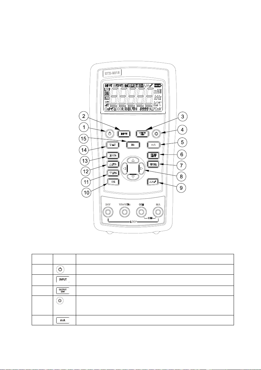
1.4 Key Description................................................................................................... 3
1.5 Display Screen..................................................................................................... 4
2 Basic Operation...............................................................................................................5
2.1 Measure and Source............................................................................................. 5
2.2 Shut Down Mode................................................................................................. 7
2.3 Backlight Brightness Adjustment.........................................................................8
3 Function Usage............................................................................................................... 9
3.1 DC V and DC mV Measurement......................................................................... 9
3.2 DC mA measurement.........................................................................................10
3.3 Current Measurement with Loop Power............................................................10
3.4 Frequency measurement.....................................................................................11
3.5 DC V Source...................................................................................................... 12
3.6 DC mV Source................................................................................................... 12
3.7 DC mA Source (active)................................................................................12
3.8 Simulating a 4- to 20-mA Transmitter............................................................... 13
3.9 Frequency Output...............................................................................................14
4 Advanced Application................................................................................................... 15
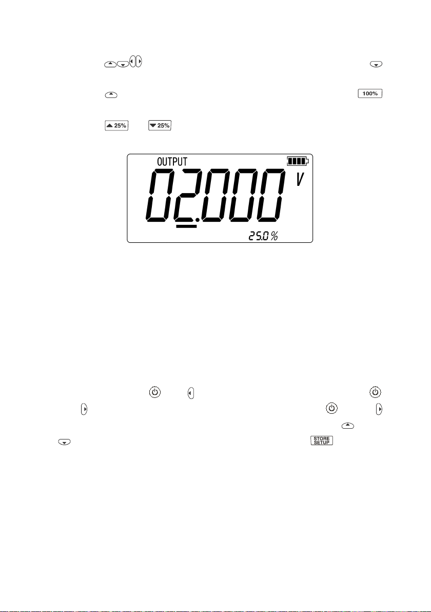
4.1 Setting 0 % and 100 % output parameters......................................................... 15
4.2 Automatic Ramp the Output.............................................................................. 16
4.3 Factory Reset......................................................................................................16
5 Power............................................................................................................................ 17
5.1 Charge................................................................................................................ 17
6 Specifications................................................................................................................ 18
6.1 DC Voltage Measurement..................................................................................18
6.2 DC voltage Source............................................................................................. 18

6.3 DC mA Measurement........................................................................................ 19
6.4 DC mA Source................................................................................................... 19
6.5 Frequency Measurement.................................................................................... 19
6.6 Frequency Source...............................................................................................20
7 Product Accessories...................................................................................................... 21
7.1 Standard Accessories......................................................................................... 21
7.2 Optional accessories...........................................................................................21
8 Warning......................................................................................................................... 22

1
1 Basic Introduction
1.1 Function
Source of voltage, current and frequency.
Measure of voltage, current, loop current and frequency.
Manual stepping and automatic stepping and ramping.
Support for PC communication
1.2 Summary of Source and Measure
Functions
Function
Measure
Source
DC V
0~30 V
0~10 V
DC mV
0~100 mV
0~100 mV
DC mA
0~24 mA
0~24 mA
Frequency
1.000Hz~99.999kHz
0.00Hz~20.000kHz
Others
24V power supply, Step, Ramp.

2
1.3 Interface (terminal) Description
Figure 1.3-1
No.
Name
Description
①
Communication and
charging connector
Connect power adaptor to charge batteries or
connect the calibrator to the computer.
②
Current terminal
terminal for current measure and source.
③
COM terminal
All measure and source public terminal.
④
V, mV, Hz terminal
terminal for voltage, milli volt, frequency
measure and source.
⑤
24V terminal
24V power supply terminal, used in LOOP mode

3
1.4 Key Description
Figure 1.4-1
No.
Description
①
Turns the power on or off
②
Selects the measurement mode
③
Selects output and analog transmitter mode.
④
Enables backlight switch display during start, enters backlight
brightness control mode.
⑤
Selects current or loop function

4
⑥
Sets and saves calibrator parameters setting
⑦
Recovers factory default setting
⑧
Sets manual output
⑨
Cycles through:
slow repeating 0%-100%-0% ramp
Fast repeating 0 % - 100 % - 0 % ramp
Repeating 0 % - 100 % - 0 % ramp in 25 % steps
⑩
Set output by 0% of span, Press and hold to store the source value
as the 0 % value
⑾
Decrements output by 25% of span.
⑿
Increments output by 25% of span.
⒀
Sets output by 100% of span, Press and hold to store the source
value as the 100 % value.
⒁
Selects DC V or DC mV function
⒂
Selects frequency function
1.5 Display Screen
Figure 1.5-1

5
2 Basic Operation
2.1 Measure and Source
This section acquaints you with some basic operations of ETX-2015/ ETX-1815.
Proceed as follows:
1. The connection of the calibrator as shown in Figure 2.1-1.
Figure 2.1-1

6
2. Press more than 2 seconds to turn on the calibrator. The calibrator checks
itself, including check on internal circuit and LCD, during which, LCD displays
all contents for 1s as shown in Figure 2.1-2:
Figure 2.1-2
3. Then the product model(2015)and automatic shutdown time(30 min)will
be displayed for 2 seconds as shown in Figure 2.1-3.
Figure 2.1-3
4. Press switch to the voltage mode.
5. Press to enter into output mode selection as shown in Figure 2.1-4.
Figure 2.1-4
6. Press and to increase or decrease 1 of the horizontal line position (the
number automatic carry but the position of the line have no change); press or
to select a digit to change.

7
7. Press to select 1 V for the output value, and then press and hold
until the buzzer works to enter 1V as the 0% value.
8. Press to select 5 V for the output value, and then press and hold
until the buzzer work to enter 5V as the 100% value.
9. Press or to step between 0 and 100% in 25% step increments.
The screen will display as shown in Figure 2.1-5.
Figure 2.1-5
2.2 Shut Down Mode
The calibrator comes with the shutdown mode enabled for a time duration set to 30
minutes (displayed for about 2 seconds when the calibrator isinitially turned on). When
the shutdown mode is enabled, the calibrator will automatically shutdown after the
time duration has elapsed from the time the last key was pressed. To disable the
shutdown mode, press and simultaneously. To enable the mode, press
and simultaneously. To adjust the time duration, press and
simultaneously, the screen will display as shown in Figure 2.2-1,then press and/or
to adjust the time between 1 and 30 minutes and then press to store the
new time duration (Without pressing any key for 5 seconds, the calibrator will quit
from the adjustment automatically).

8
Figure 2.2-1
2.3 Backlight Brightness Adjustment
To adjust the brightness of backlight, proceed as follows:
1. Press until the buzzer works, then the screen will display as shown in Figure
2.3-1:
Figure 2.3-1
2. Press and to adjust the brightness of backlight.
3. Press to save brightness level, will appear and then the calibrator
will enter into the work mode(Without pressing key for 5 seconds, the calibrator
will exit from the adjustment automatically).

9
3 Function Usage
3.1 DC V and DC mV Measurement
The default function after turn on is DC V measurement, press to select DC V
or DC mV and the connection is shown in Figure 3.1-1:
Figure 3.1-1

10
3.2 DC mA measurement
Press to select DC mA (unit: mA). The connecting method is shown in Figure
3.2-1.
Figure 3.2-1
3.3 Current Measurement with Loop Power
The loop power function activates a 24 V supply in series with the current measuring

11
circuit, allowing you to test a transmitter when it is disconnected from plant wiring. To
measure current with loop power, proceed as follows:
1. Connect the calibrator to the transmitter current loop terminals as shown in
Figure 3.3-1.
2. Press until and appear simultaneously.
Figure 3.3-1
3.4 Frequency measurement
Press to select frequency measurement, the connecting mode is same to that of
voltage. The screen will display as shown in Figure 3.4-1.

12
Figure 3.4-1
3.5 DC V Source
Press and to select the DC V output function, the connection mode is
same to that of voltage measurement.
3.6 DC mV Source
Press and to select the DC mv output function, the connection mode is
same to that of voltage measurement.
3.7 DC mA Source (active)
Press and to select mode, the connection mode is shown in
Figure 3.7-1:

13
Figure 3.7-1
When the output current is overload, the LCD will shown which indicates the
overload and meanwhile, the main display area flashes, shown in Figure 3.7-2:
Figure 3.7-2
3.8 Simulating a 4- to 20-mA Transmitter
Simulating is a special mode of operation in which the calibrator is connected into a
loop in place of a transmitter and supplies a known, settable test current.
Proceed as follows:
1. Connect the 24 V loop power source as shown in Figure 3.8-1.

14
2. If necessary, press and to select and (simulation)
mode.
Figure 3.8-1
3.9 Frequency Output
Press and to select the frequency output function, the connection
mode is same to that of voltage measurement. The screen will display as shown in
Figure 3.9-1.
Figure 3.9-1
If necessary, press to select other ranges as shown in Figure 3.9-2.
Figure 3.9-2

15
4 Advanced Application
4.1 Setting 0 % and 100 % output
parameters
As for stepping operation and percentage display, 0% and 100% should be set before
using. The default values have been set when delivered from the factory and set values
are listed below:
Source function
0%
100%
DC V
0.000 V
10.000 V
DC mV
0.00 mV
100.00 mV
DC mA
4 .000 mA
20.000 mA
Frequency – 200Hz
0.00 Hz
200.00 Hz
Frequency – 2000Hz
0.0 Hz
2000.0 Hz
Frequency – 20kHz
0 .000 kHz
20 .000 kHz
The default set values may not meet your requirements, so you can reset them. Press
and hold or to reset 0% and 100% value until the buzzer works. The
reset value will be stored in the storage space of the calibrator automatically and
remains effective after restart. Now you can start operation with the reset value:
Manually stepping an output with 25 % increments.
Jump between the 0 and 100 % span points by momentarily pushing or
.

16
4.2 Automatic Ramp the Output
Auto ramping gives you the ability to continuously apply a varying stimulus from the
calibrator to a transmitter, while your hands remain free to test the response of the
transmitter. When you press , the calibrator produces a continuously repeating
0 % - 100 % - 0 % ramp in your choice of three ramp waveforms :
0%-100%-0% 40-second smooth ramp
0%-100%-0% 15-second smooth ramp
0%-100%-0% Stair-step ramp in 25 % steps, pausing 5 seconds at each
step.
Press any key to quit ramp output function.
4.3 Factory Reset
Factory rest consists of the following items:
The upper and lower working modes recover to DC V measurement function.
Automatic shutdown time is reset to be 30 min and becomes effective.
LCD backlight brightness is reset to be 60%.
Output range is recovered to be factory default.
Start the calibrator and press until the buzzer works and the recovery of factory
default will enter working mode when the recovery is completed.

17
5 Power
The calibrator needs 6 disposable LR03 model (size 7) alkaline batteries or 6 R03
model (size 7) nickel-metal hydride batteries (or nickel-cadmium batteries). The
longest service life of alkaline batteries can reach 50 hours.
A 12V/1A power adaptor is used for charging and providing working power for the
calibrator.
5.1 Charge
When the battery indicator is pointed at , the remaining electric quantity is less
than 20%. Charge is necessary for normal operation of the calibrator. The LCD
backlight will start operation and the will display on the screen when the power
adaptor is used. If the battery indicator flashes, the calibrator will be in the
charging process, after which the battery indicator will stop flashing.
The calibrator will stop charge automatically in case of the following circumstances:
Disposable batteries are used.
Electric quantity is enough.
This manual suits for next models
1
Table of contents
Other East Tester Test Equipment manuals

East Tester
East Tester ET44 Series User manual

East Tester
East Tester ET5420 User manual

East Tester
East Tester ET5300 User manual

East Tester
East Tester ET1300 User manual

East Tester
East Tester ET3325 User manual

East Tester
East Tester ET2725A User manual

East Tester
East Tester ET5410 User manual

East Tester
East Tester ET-AY30 User manual

East Tester
East Tester ET-2712 RTD User manual