manuals.online logo
Brands
  1. Home
  2. •
  3. Brands
  4. •
  5. Eaton
  6. •
  7. Control Unit
  8. •
  9. Eaton S611 Manual

Eaton S611 Manual

Eective July 2010
Supersedes April 2010
Installation Leaet IL04209006E
PROFIBUS Module for use with
Motor Insight, C440 and S611
Installation
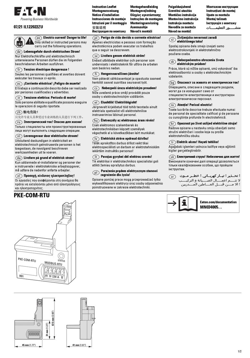
The PROFIBUS module is designed to be used in
industrial applications and installed in accordance
with this document.
Mount the Module
To mount the PROFIBUS adapter to Motor
Insight® or C440-COM-ADP the following pro-
ceedure must be preformed.
• Place the tabs opposite the PROFIBUS con-
nector into the lower slots provided on the
Motor Insights right side.
• Pivot the module on the lower tabs toward
the Motor Insight.
• Gently press the module and Motor Insight
together.
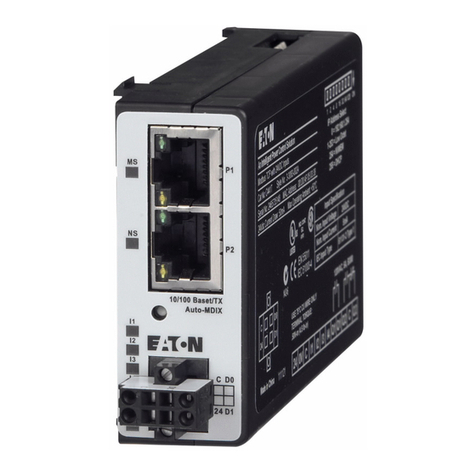
Connect the PROFIBUS Adapter to PROFIBUS
Connect the PROFIBUS terminal to the PROFIBUS
DB9 connector located on the side of the module.
The connector has screws for positive retention to
eliminate accidental unplugging.
Connect 24 Vdc control power to the 5-position
header.
• The connector has screws for positive reten-
tion to eliminate accidential unplugging.
• Use one wire per terminal.
Set the PROFIBUS address
The PROFIBUS address is set using the DIP
switches located on the face of the module. The
PROFIBUS address is binary with the major units
numbered to the left of the switch on the side
label. Adding up the major units set to ON deter-
mines the address of the module.
Example: To set the address to 25, start from the
switch mark 32 and set the switches to Off (32),
ON (16), ON (8), OFF (4), OFF (2) ON (1) (16+8+1
=25).
Note: Address is only updated upon power up.
The PROFIBUS baud rate is set automatically
using an auto baud technology, there is no need
to set the baud rate. For more information on the
PROFIBUS attributes and how to modify them,
refer to the appropriate user manual. Motor Insight
MN04209001E, C440 MN04201001E or S611
MN03902011E.
The GSD file is located on the Eaton web site, go
to www.eaton.com.
C441S - 120 Vac Input Specification
Specification Value
Number of Inputs 4
Nominal Voltage 120 Vac
Nominal Current 15mA
Operating Frequency 50/60Hz
Signal Delay max. 30ms
Input type IEC 61131-2
Type 1 Digital
C441Q - 24 Vdc Input Specication
 
 
 
 



































 
 
 
 














































 
 
 
 










































2
Installation Leaet IL04209006E
Eective July 2010
PROFIBUS Module for use with
Motor Insight, C440 and S611
EATON CORPORATION www.eaton.com
Specification Value
Number of Inputs 4
Nominal Voltage 24 Vdc
Nominal Current 5mA
Type Current Sinking
Input Type IEC 61131-2, Type 1 Digital
Max 24 Vdc Source Current 50mA
PROFIBUS Adapter Setup and Configuration
Configure C441 Profibus Adapter
1. Load the gsd le for the C441 Probus Adapter into the Master’s
conguration tool.
2. Select and add the C441 Probus Adapter to the network
conguration.
3. The default conguration for the C441 Probus Adapter is a
StandAlone IO base. If the C441 Probus Adapter is to connect
to a base device; remove the modules from all 28 slots of the
default conguration.
4. Select and add the attached device’s base module
to slot 1 of the C441 Probus Adapter conguration.
NOTE: The appropriate base module MUST be placed in slot 1 of
the conguration. Failure to do so will cause conguration to fail.
5. Select and add the desired modules for the data exchange into
slots 2 - 28. Select only those modules supported by the base
module (See the base device’s user manual for a list of sup-
ported modules)
Example Conguration:
I/O module Type Description
C441 MotorInsight Base base - no IO Attached Device
Com Adapter Outputs output - 1 byte Controls C441 adapter
outputs
MI Command Register output - 2 bytes Controls MI Relay-
start/stop
Com Adapter Inputs input - 1 byte Status of C441 adapt-
er inputs
MI RMS Current Ave input - 2 bytes Average rms current
reading
MI RMS Voltage Ave input - 2 bytes Average rms voltage
reading
MI Total Kilowatts input - 2 bytes Total power reading
Setup C441 Probus Adapter Device Parameters
1. Select the C441 Probus Adapter to display its device param-
eters.
2. Set the “Enable Device Parameters & Adapter Outputs ComLos
Behavior” parameters.
Note: To enable writing of the device parameters into the attached
base device “Enable Device Parameters” must be set to “Download
Device Parameters”.
Setup the Device Parameters
1. Select the base module in the conguration to display its device
parameters. The base module contains the parameters to en-
able/disable faults, set thresholds, etc. for the attached device.
Example: The following parameters can be found in C441
MotorInsight Base Module
• CT Multiplier
• Overload FLA
• Overload Trip Class
• GND Fault Trip Level
• Low KW Trip Level
• High KW Trip Level
• Under Voltage Trip Level
• Over Voltage Trip Level
After all conguration is complete, save and download the new
conguration settings to the Master(PLC) & C441 Probus
Adapter.
Probus Diagnostics
The C441 Probus Adapter provides the user with status information
along with fault and warning data relevant to the operation of the
attached base module. Fault and warning information is presented to
the user through extended diagnostics. All fault information is sent
to the Master as high priority diagnostic messages (ext. diag. bit set
in diagnostic message). All warning information is sent as low prior-
ity diagnostic messages (ext diag. bit clear). Low priority diagnostic
messages are issued as the fault condition clears.
See the User Manual for the attached base module’s diagnostic mes-
sage bit denitions
Environmental Ratings of the Module
Transportation
and Storage
Temperature -40ºC to 85ºC (-40ºF to 185ºF)
Humidity 5 - 95 % non-condensing
Operating
Temperature -20ºC to 50ºC (-4ºF to 122ºF)
Humidity 5 - 95 % non-condensing
Altitude Above 2000meters (6600feet)
consult factory
Shock
ICE 60068-2-27
15G any direction for
11 milliseconds
Vibration
IEC 60068-2-6
3G in any direction
Polution Degree 3
3
Installation Leaet IL04209006E
Eective July 2010
PROFIBUS Module for use with
Motor Insight, C440 and S611
EATON CORPORATION www.eaton.com
Approvals / Certications
Electrical / EMC
ESD Immunity +/- 8kV air, +/- 4kV contact
Radiated Immunity (IEC61000-4-3) 10V/m 80-1000 MHz, 80%
amplitude modulation @
1kHz
Fast Transient (IEC61000-4-4) +/- 2kV communications
Surge (IEC61000-4-5) +/- 2kV shield-to-ground
RF Conducted (IEC610000-4-6) 10V, 0.15 – 80MHz
Ingress Protection Code IP20
Radiated and Conducted Emissions EN55011 (CISPR 11) Class A
Agency Certifications UL® 508
cUL® (CSA C22.2 No. 14)
CE (Low Voltage Directive)
PROFIBUS Certification
Module Electrical Requirements
Voltage Range 18 - 30 Vdc
Current Draw Approx. 30 mA
Notes
For use with Eaton UL Listed Power Supply Catalog Nos. PSS55A,
PSS55B, PSS55C, or PS160E.
Any UL Listed isolated power supply with a maximum of 30 Vdc
output may be used, provided that a UL Listed or Recognized Fuse
rated no more than 3A maximum be installed.
5pin 24 VDC Power, RS485 Connector

Installation Leaet IL04209006E
Eective July 2010
PROFIBUS Module for use with
Motor Insight, C440 and S611
Eaton Corporation
Electrical Sector
1000 Cherrington Parkway
Moon Township, PA 15108
United States
877-ETN-CARE (877-386-2273)
Eaton.com
© 2009 Eaton Corporation
All Rights Reserved
Printed in USA
Publication No. IL04209006E
July 2010, Rev. 007
PowerChain Management is a registered
trademark of Eaton Corporation.
All other trademarks are property of their
respective owners.

Other manuals for S611

3

This manual suits for next models

2

Other Eaton Control Unit manuals

Eaton Cutler-Hammer PanelMate ePro PS Series User manual

Eaton

Eaton Cutler-Hammer PanelMate ePro PS Series User manual

Eaton 33 User manual

Eaton

Eaton 33 User manual

Eaton XVM PCBA Series User manual

Eaton

Eaton XVM PCBA Series User manual

Eaton HMi VU Series Manual

Eaton

Eaton HMi VU Series Manual

Eaton CMA User manual

Eaton

Eaton CMA User manual

Eaton XMCSPAN-001 Guide

Eaton

Eaton XMCSPAN-001 Guide

Eaton ELC-EX08NNSN User manual

Eaton

Eaton ELC-EX08NNSN User manual

Eaton EC4E-221-6D4T1 Manual

Eaton

Eaton EC4E-221-6D4T1 Manual

Eaton EP Control User manual

Eaton

Eaton EP Control User manual

Eaton Powerware 9395 User manual

Eaton

Eaton Powerware 9395 User manual

Eaton MMX-COM-PC Manual

Eaton

Eaton MMX-COM-PC Manual

Eaton Vickers SF4-140-20-002-10 User manual

Eaton

Eaton Vickers SF4-140-20-002-10 User manual

Eaton OPTCB RS-485 User manual

Eaton

Eaton OPTCB RS-485 User manual

Eaton PKE-SWD-32 Manual

Eaton

Eaton PKE-SWD-32 Manual

Eaton Char-Lynn 5 Series User manual

Eaton

Eaton Char-Lynn 5 Series User manual

Eaton 145406 Installation and operating instructions

Eaton

Eaton 145406 Installation and operating instructions

Eaton Power Xpert C445 Manual

Eaton

Eaton Power Xpert C445 Manual

Eaton ZB150 Series Manual

Eaton

Eaton ZB150 Series Manual

Eaton ELC-CADNET User manual

Eaton

Eaton ELC-CADNET User manual

Eaton PKE-SWD-CP Manual

Eaton

Eaton PKE-SWD-CP Manual

Eaton Form 4D Recloser Control User manual

Eaton

Eaton Form 4D Recloser Control User manual

Eaton xComfort CAEE-02/01 User manual

Eaton

Eaton xComfort CAEE-02/01 User manual

Eaton EWFFSC15 User manual

Eaton

Eaton EWFFSC15 User manual

Eaton EC4E-221-6D4T1 Manual

Eaton

Eaton EC4E-221-6D4T1 Manual

Popular Control Unit manuals by other brands

Emerson BM6X Series instruction manual

Emerson

Emerson BM6X Series instruction manual

Time Electronics 7085A user manual

Time Electronics

Time Electronics 7085A user manual

AUMA AC 01.2 manual

AUMA

AUMA AC 01.2 manual

DEUTSCHMANN AUTOMATION LOCON 200 instruction manual

DEUTSCHMANN AUTOMATION

DEUTSCHMANN AUTOMATION LOCON 200 instruction manual

Bender ATICS UMA710-2-63-ISO manual

Bender

Bender ATICS UMA710-2-63-ISO manual

ION Damper Control Installation and start-up instructions

ION

ION Damper Control Installation and start-up instructions

Acconeer XM112 Hardware user's guide

Acconeer

Acconeer XM112 Hardware user's guide

VAT 244 Series Installation, operating,  & maintenance instructions

VAT

VAT 244 Series Installation, operating, & maintenance instructions

HBX Modulating Module 0100 installation manual

HBX

HBX Modulating Module 0100 installation manual

Pentair Autotrol Performa 400 Series Service manual

Pentair

Pentair Autotrol Performa 400 Series Service manual

JYTEK USB-61210 user manual

JYTEK

JYTEK USB-61210 user manual

Huawei MU709s-2 Hardware guide

Huawei

Huawei MU709s-2 Hardware guide

Mitsubishi Electric ACH1 installation manual

Mitsubishi Electric

Mitsubishi Electric ACH1 installation manual

COBHAM 3011 user manual

COBHAM

COBHAM 3011 user manual

Kontron SMARC sXAL user guide

Kontron

Kontron SMARC sXAL user guide

Heath Zenith 5868 instruction manual

Heath Zenith

Heath Zenith 5868 instruction manual

Genie 38647R.S Replacement instructions

Genie

Genie 38647R.S Replacement instructions

Danfoss AME 13 installation guide

Danfoss

Danfoss AME 13 installation guide

manuals.online logo
manuals.online logoBrands
  • About & Mission
  • Contact us
  • Privacy Policy
  • Terms and Conditions

Copyright 2025 Manuals.Online. All Rights Reserved.