manuals.online logo
Brands
  1. Home
  2. •
  3. Brands
  4. •
  5. Eaton
  6. •
  7. Controllers
  8. •
  9. Eaton A200 User manual

Eaton A200 User manual

Effective May 2011
Supersedes April 1988
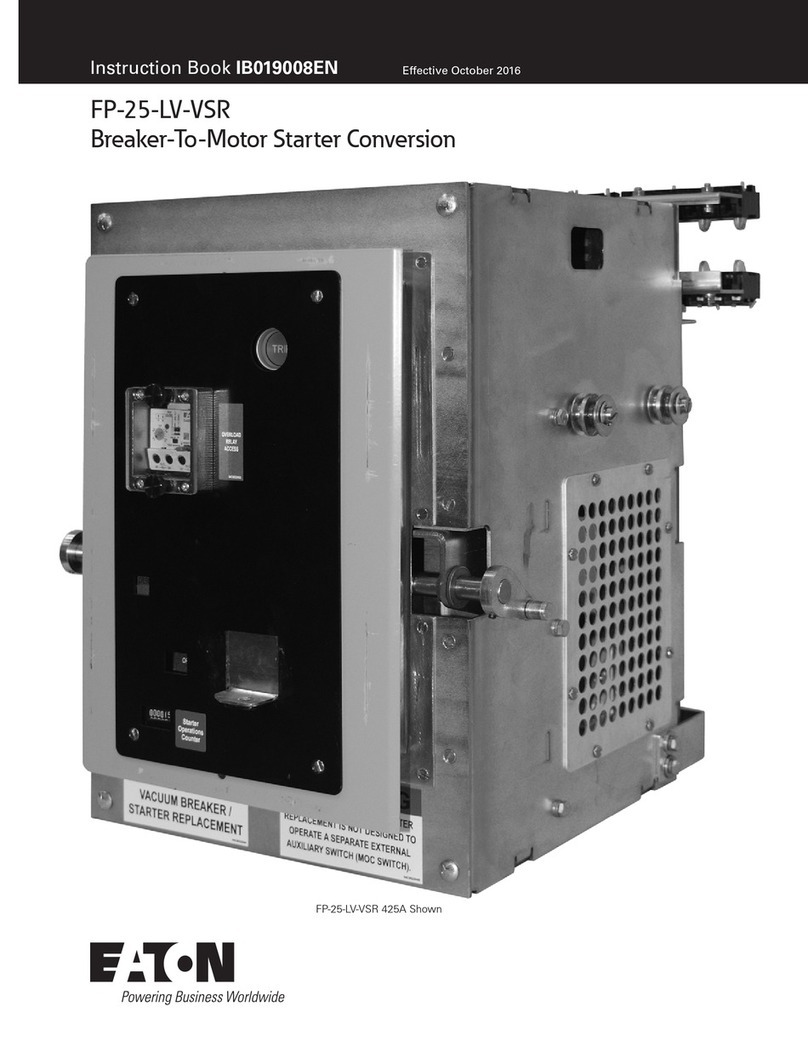
Instruction Leaflet IL15465
Instructions for A200 Size 3 or 4, 3 Pole
Motor Controller
THE CONTACTORS
The A200 motor controller, when wired as shown in Figures
5 and 6, will operate as a full voltage starter and will give
protection against overload, but not against short-circuit currents,
when wired and provided with overload relay (OLR) heaters as
listed in heater selection tables or when used with any means of
inherent protection activated by motor temperature.
The controller should be protected against short circuits by
providing branch circuit protection not to exceed the maximum
protective device ratings listed in Table I.
This industrial type control is designed to be installed, oper-
ated, and maintained by adequately trained workmen. These
instructions do not cover all details, variations, or combinations of
the equipment, its storage, delivery, installation, check out, safe
operation, or maintenance. Care must be exercised to comply with
local, state, and national regulations, as well as safety practices,
for this class of equipment.
AUXILIARY CONTACTS - TYPE J
A J20 with two normally-open poles is supplied mounted in the
upper left hand corner recess of the contactor. One pole is used
as the holding circuit auxiliary.
2
Instruction Leaflet IL15465
Effective May 2011
A200 Size 3 or 4, 3 Pole Motor Controller
EATON CORPORATION www.eaton.com
AUXILIARY CONTACTS - TYPE J (Cont.)
A maximum of four auxiliary units can be installed with ter-
minals either in line or in a right angle relationship to the power
poles. Auxiliary contacts mount by means of a spring clip and
retainer screw. To remove the unit rotate the retainer screw several
times (counterclockwise) and then slide the auxiliary contact unit
out of the recess.
TYPE A OVERLOAD RELAY (See Figure 3)
The A200 motor controller can be equipped with aType A block
type non-ambient compensated overload relay (unmarked and
with red reset rod) or with a block type temperature compensated
overload relay (marked “ambient compensated” and with gray
reset rod). The relay is of the bimetal actuated type equipped with
trip indicator, trip adjustment covering ± 15% of rating and a
normally closed control contact. It may be operated with either
hand or automatic reset.
Reset operation is determined by the position of the plate on
the load side of the overload base. Position the reset plate away
from the panel to set the “hand” position. Loosen the locking
screw, move the reset plate toward the panel, and retighten the
screw to set the “auto” position.
Automatic reset should not be used with 2-wire control circuits
where automatic starting of the motor may be hazardous
AUXILIARY CONTACTS - TYPE J (Cont.)
This A200 motor controller is usually equipped with a Type B
block type ambient compensated overload relay (with gray reset
rod). The controller can also be supplied with a non-ambient
compensated overload relay (with red reset rod). The relay is of
the bimetal actuated type equipped with a normally closed
control contact. An optional isolated normally open control circuit
is available for field mounting. When the overload relay trips, a
yellow dot will appear flush with the molded surface below the
reset rod. Resetting the relay returns this indicator to its normal
concealed position.
HEATERS
Heaters are not included with the motor controller and must
be ordered separately per the heater selection table and the
information listed below. When installing heaters be sure that
connecting surfaces are clean and heaters are attached securely
to the relay in the proper location with the screws provided. The
trip rating of a heater in a 40°C ambient is 125% of the minimum
full load current shown in Table 1. When tested at 600 percent of
its trip rating, the relay will trip in 20 seconds or less.
WARNING: To provide continued protection against fire and
shock hazard, the complete overload relay must be replaced if
burnout of a current element occurs. See Table II.
3
Instruction Leaflet IL15465
Effective May 2011
A200 Size 3 or 4, 3 Pole Motor Controller
EATON CORPORATION www.eaton.com
Heaters should be selected on the basis of the actual full load
current and service factor as shown on the motor nameplate or
in the manufacturer’s published literature. When the service factor
of the motor is 1.15 to 1.25, select heaters from the heater
application table. If the service factor of the motor is 1.0, or there
is no service factor shown, or a maximum of 115% protection is
desired, select one size smaller heater than indicated. When motor
and overload relay are in different ambients and when using non-
compensated overload relays, select heaters from the table using
adjusted motor currents as follows: decrease rated motor current
1 % for each °C motor ambient exceeds controller ambient.
Increase rated motor current 1% for each °C controller ambient
exceeds motor ambient.
COIL
The A200 motor controller is available with a single or dual
voltage coil. When equipped with a single voltage coil, the
contactor is wired as shown in Figure 6. A connection diagram
for a dual voltage coil is shown in Figure 4. When supplied with
a dual voltage coil, the motor controller is normally wired for the
high voltage connection. The wiring may be changed to the low
voltage connection by removing and reconnecting the jumpers as
illustrated below.
4
Instruction Leaflet IL15465
Effective May 2011
A200 Size 3 or 4, 3 Pole Motor Controller
EATON CORPORATION www.eaton.com
SHORT-CIRCUIT WITHSTAND RATINGS
Each Size 3 or Size 4 motor controller is suitable for use on a
circuit capable of delivering not more than current (in rms symmetrical
amperes) shown in Table IV or Table V in circuits rated not more
than the voltage shown in the applicable table.
5
Instruction Leaflet IL15465
Effective May 2011
A200 Size 3 or 4, 3 Pole Motor Controller
EATON CORPORATION www.eaton.com
MAINTENANCE - First Turn Off Power
To Inspect Contacts
Refer to Figure 7. Loosen the two arc box assembly screws (7)
located immediately above and below the nameplate and remove
the arc box (8). Contacts (5) are visible. Retighten the screws per
Table VII.
To Replace Contacts
After removing the arc box and with replacement contacts at
hand, compress the overtravel spring (12) and remove the moving
contact (5) from the crossbar (6). Remove the retaining screws
(11) and lift out the stationary contact carriers (14).
To replace contacts, reverse the above procedure making sure
that stationary contacts are secure, (see Table VII) moving
contacts are free to move overtravel springs are seated and the
crossbar moves freely when the arc box is in position.
The silver cadmium oxide contact buttons need NO dressing or
lubricant throughout their life.
Important - Replace all contacts and springs as a group to avoid
misalignment.
To Replace The Coil
Refer to Figure 7. Loosen the assembly screws (10) located
to the immediate left and right of the arc box. Remove connector
straps to the overload relay. Pull the loosened upper base structure
(9) forward.
Pull the coil (1) from the upper base, plug in a new coil, replace the
upper base structure and check the auxiliary contacts for secureness
when repositioning the upper base. Tighten the assembly screws
and the connector straps screws referring to Table VII.
Magnet - Armature Assembly
Self alignment and permanent air gap features of the magnet
armature make replacement unnecessary. Mating pole face
surfaces should be kept clean.
Arcbox must be in place when controller interrupts a cir-
cuit.
Instruction Leaflet IL15465
Effective May 2011
A200 Size 3 or 4, 3 Pole Motor Controller
Eaton Corporation
Electrical Sector
1111 Superior Ave.
Cleveland, OH 44114
United States
877-ETN-CARE (877-386-2273)
Eaton.com
© 2011 Eaton Corporation
All Rights Reserved
Publication No. IL15465 / 001
May 2011
Eaton is a registered trademark of Eaton
Corporation.
All other trademarks are property of their
respective owners.

Other Eaton Controllers manuals

Eaton CGLine+ Touchscreen Controller User manual

Eaton

Eaton CGLine+ Touchscreen Controller User manual

Eaton Digitrip RMS Manual

Eaton

Eaton Digitrip RMS Manual

Eaton ELC-PA10AADR User manual

Eaton

Eaton ELC-PA10AADR User manual

Eaton RTC-100 User manual

Eaton

Eaton RTC-100 User manual

Eaton Cutler-Hammer DS6 Series Manual

Eaton

Eaton Cutler-Hammer DS6 Series Manual

Eaton Cuttler-Hammer Pow-R-Command 100 Instruction manual

Eaton

Eaton Cuttler-Hammer Pow-R-Command 100 Instruction manual

Eaton ELC-PB Owner's manual

Eaton

Eaton ELC-PB Owner's manual

Eaton COOPER POWER SERIES User manual

Eaton

Eaton COOPER POWER SERIES User manual

Eaton easyControl EC4-200 User manual

Eaton

Eaton easyControl EC4-200 User manual

Eaton CGLine+ Operating and maintenance instructions

Eaton

Eaton CGLine+ Operating and maintenance instructions

Eaton EMS2 SWD Series User manual

Eaton

Eaton EMS2 SWD Series User manual

Eaton XC-152 Series User manual

Eaton

Eaton XC-152 Series User manual

Eaton DS7-34 SX041N0 Series Manual

Eaton

Eaton DS7-34 SX041N0 Series Manual

Eaton ELC2 Series User manual

Eaton

Eaton ELC2 Series User manual

Eaton Jockey XTJP User manual

Eaton

Eaton Jockey XTJP User manual

Eaton xComfort CSAU-01/01-10I User manual

Eaton

Eaton xComfort CSAU-01/01-10I User manual

Eaton Jockey lite User manual

Eaton

Eaton Jockey lite User manual

Eaton CJAU-01/04 Series Manual

Eaton

Eaton CJAU-01/04 Series Manual

Eaton CGLine+ Web-Controller User manual

Eaton

Eaton CGLine+ Web-Controller User manual

Eaton xComfort CHCA-00 User manual

Eaton

Eaton xComfort CHCA-00 User manual

Eaton COOPER POWER SERIES Manual

Eaton

Eaton COOPER POWER SERIES Manual

Eaton SC100 User manual

Eaton

Eaton SC100 User manual

Eaton AMPGARD Manual

Eaton

Eaton AMPGARD Manual

Eaton EVER-Tap Manual

Eaton

Eaton EVER-Tap Manual

Popular Controllers manuals by other brands

ABB MotiFlex e180 Application guide

ABB

ABB MotiFlex e180 Application guide

Carel ADP 30 pAD Series quick start guide

Carel

Carel ADP 30 pAD Series quick start guide

FRANCE ETUVES C3030 Original instructions

FRANCE ETUVES

FRANCE ETUVES C3030 Original instructions

Linear Technology LTC3805/-5 quick start guide

Linear Technology

Linear Technology LTC3805/-5 quick start guide

Nice M-BOARD Installation and use instruction

Nice

Nice M-BOARD Installation and use instruction

Penn TC3B23 installation guide

Penn

Penn TC3B23 installation guide

MC Electronic DORADO MX3 Instructions for use

MC Electronic

MC Electronic DORADO MX3 Instructions for use

HP E-MSM720 installation guide

HP

HP E-MSM720 installation guide

Aerotech Ensemble HLe Hardware manual

Aerotech

Aerotech Ensemble HLe Hardware manual

MKS Compact Closed Loop Picomotor user manual

MKS

MKS Compact Closed Loop Picomotor user manual

CAME RIOCN8WS manual

CAME

CAME RIOCN8WS manual

Hubbell Electric Fire Pump Controllers LXi 1800 Specifications

Hubbell

Hubbell Electric Fire Pump Controllers LXi 1800 Specifications

SSS Siedle EC 602-03 Programming instructions

SSS Siedle

SSS Siedle EC 602-03 Programming instructions

Leviton FEBC Operation manual

Leviton

Leviton FEBC Operation manual

Nexus NEO manual

Nexus

Nexus NEO manual

Erreka ERTAIN 4 SYSTEM installation manual

Erreka

Erreka ERTAIN 4 SYSTEM installation manual

Kostal inveor operating manual

Kostal

Kostal inveor operating manual

Autonics TM2-22RB user manual

Autonics

Autonics TM2-22RB user manual

manuals.online logo
manuals.online logoBrands
  • About & Mission
  • Contact us
  • Privacy Policy
  • Terms and Conditions

Copyright 2025 Manuals.Online. All Rights Reserved.