8. Installation
8.1 General
The respective national regulations, IEC/EN 60079-14 as well
as the general rules of engineering which apply to the
installation and operation of explosion protected apparatus
must be observed!
Improper installation and operation may result in the
explosion protection method being compromised and
invalidate the guarantee.
8.2 Mounting luminaire
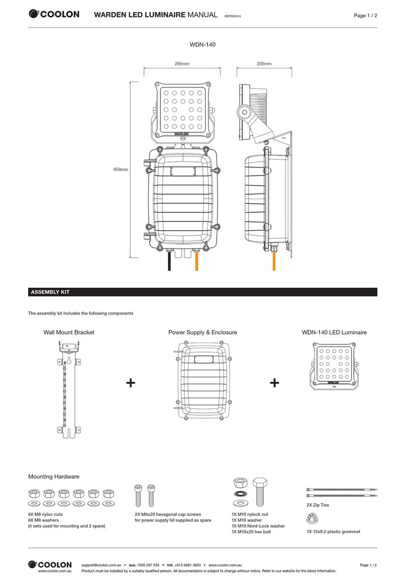
8.2.1 Mounting bracket
Only use the accompanying mounting bracket! Securely
fasten the mounting bracket to a suitable base with
sufficient load-bearing capacity. The mounting should be
secured with M8 bolts, lock washers and nuts.
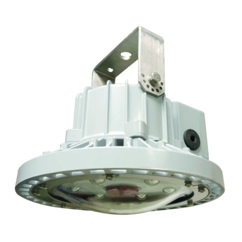
8.2.2 Pole mounting
The pole mounted light fitting is mounted and installed in
the following order:
–Unscrew the three recessed head screws in the cover of
the pole connecting compartment, see fig. 5.1, item 1.
–Open the connecting compartment by folding down the
cover, see fig. 5.5, item 2.
–Pull the stay shackle of the cable entry socket up to its
stop and take off the cover plate, see fig. 5.5, item 3.
–Remove the cable entry sockets from the guiding
grooves in the connecting compartment.
–Push the 42mm diameter pole (fig. 5.5, item 4) into the
opening of the light fitting, see fig. 5.4.
–Adjust the light fitting and screw down the preassembled
M 6 special screws, applying a torque of 3.0 Nm, see fig.
5.5, item 5.
–Introduce the cable through the tube and strip the
insulation to the required length.
–Introduce the cable through the Ex cable entry (KLE) and
tighten it down with the pressure screw of the cable entry
(see Technical data).
–The complete support (with the cable being introduced)
is put into the guiding grooves of the pole mounted light
fitting, see fig. 5.5, item 6.
–Lock the support with the stay shackle, see fig. 5.5, item
3.
–Insert the cable into the pull-relief and tighten it down,
see fig. 5.5, item 7.
–Then connect the cable in accordance with the terminal
marking.
The minimum distance between the luminaire and
illuminated surface, directly in front of the luminaire, is 0.5
meter. The lighting must not be illuminated when at a
distance of less than 0.5m from inflammable material
8.3 Cable entries/Plugs and Breathing valve
The “Increased safety (Exe)" properties must be preserved
when mounting cable entry/plug and breathing valve.
Unused holes must be closed with certified plug to establish
the Exe protection category. The cable glands/plugs and
breathing valve should be Ex tb certified if the whole
product is Ex tb certified also. Cable entries sealing
washer(if required by manual of cable gland/plug) must be
used to obtain IP66.
IM0535 Ver.4 2023/10 Cooper Electric (Changzhou) Co., Ltd. Page 3/6
The authoritative mounting guidelines for the
cable glands and breathing valve used must be
observed. Mounting the selected cable entries acc.
type and dimensions of the main connection cable
following their manufacturer instructions. The
cable temperatures are given as the rise over the
max. rated ambient (Tamb). This allows the user
to adjust the cable specification for actual
maximum site ambient. Only heat resistant cable
according to the data on the type label may be
used! The max. conductor size is 6mm². The
standard looping cable size is 4mm².
8.4 System modes
8.4.1 Independent system mode:
8.4.1.1 In the event of a mains failure, an
automatic changeover to emergency operation
occurs.
8.4.1.2 Battery Indicator Matrix:
8.4.1.3 Battery charging:After first mains
connection, an uninterrupted charging time for 24
hours is strongly recommended. A charge-
discharge activation cycle should be applied if
stored for more than 6 months.
8.4.2 Inhibit switch system mode:
8.4.2.1 The emergency light function can be
separately switched on and off via a inhibit switch
installed outside in the event of a mains failure.
8.4.2.2 If using the inhibit switch, remove the wire
on the small terminal (refer wiring diagram).
8.5 Opening/closing the luminaire
8.5.1 General
The equipment must be de-energised before
opening! All gasket seals must be clean and
undamaged before closing the luminaire! Make
sure the luminaires is fully closed before
operation!
8.5.2 Exe chamber cover
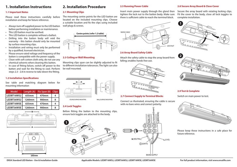
Open the buckles and remove the PC cover. And carry
out the steps in reverse order to close the luminaire.
Check all buckles to ensure a secure fit during
operation.(Illustration 4 )
8.6 Electrical connection
The electrical connection of the luminaire must only be
carried out by qualified electricians.
Make sure the supply voltage is the same as the
luminaire voltage! Use proper supply wiring as
specified on the nameplate of the luminaire and in this
instructions! Excessive tightening may affect or damage
the connection.
8.6.1 Wire connection
The conductors shall be connected with special care in
order to maintain the explosion category.
The conductor itself shall not be damaged.
The min. and max. conductor cross-sections
shall be observed (see technical data). All
terminals, used and unused, shall be tightened
between 1.2Nm for Exe T6P and 0.6~0.8Nm for
MK3/2/E. Main connection: See wiring diagram.
Remove the single core cable which shorts the
terminals of MK3/2/E when installing the inhibit
switch.
Type of connected conductors: Rigid with cable
lug, flexible with ferrule, pin cable lug or cable
lug.
9. Putting into operation
Prior to putting the apparatus into operation, the tests
specified in the relevant national regulations shall be
carried out. Insulation measurements may only be
carried out between PE and the external conductor L1
(L2, L3) as well as between PE and N.
- Measurement voltage: Max. 1.5 KV AC
- Measurement current: Max.5 mA
- The luminaire may only be operated when closed.
- It is generally recommended (see IEC/EN 60079-14)
that you ensure the type of protection of the
construction is not impaired during installation.
10. Maintenance/Servicing
10.1 General
The relevant national regulations which apply to the
maintenance/servicing of electrical apparatus in
explosive atmospheres, shall be observed (EN/IEC
60079-17). The interval between maintenance depends
upon the ambient conditions and the hours of
operation. The recommendations given within EN/IEC
60079-17 for recurring checks must be observed.
10.2 Checks
The equipment must be de-energised before opening
Visual inspection should be carried out at a minimum
of 12 monthly intervals and more frequently if
conditions are severe, refer to EN/IEC 60079-17. The
time between luminaire changes could be very
infrequent and this is too long a period without
inspection.
10.3 Routine Examination
During maintenance, the parts affecting the level
of protection must be checked in particular:
- Ensure the luminaire is lit when energised and
examine the enclosure and cover for any signs of
cracks and damage.
- When de-energised and left to cool, there should be
no significant sign of internal moisture. If there are
signs of water ingress, the luminaire should be opened
up, dried out, and any likely ingress points eliminated
by re-gasketing, re-greasing or other replacement.
- Check the gasket of pc cover and LED housing for any
damage or permanent set and replace as required.
- Check wiring into terminals, glands and blanking plugs
are securely fitted.
- To maintain the light output, clean the protective pc
cover periodically with a damp cloth or a mild cleaning
fluid.
If this product is used in the combustible dust area, the
outside of the enclosure must be cleaned on a regular
basis to prevent accumulation of dust.
7. Type configuration and Max. Ambient and Temperature Ratings
Charging Fully Charged Emergency Damaged
Green light
"blinking"
Green light
"steady on"
Red light
“blinking “
Red light
“steady on"
Std. Cat No.
