IM0217.Revision 5 05/17 Page 3 of 3
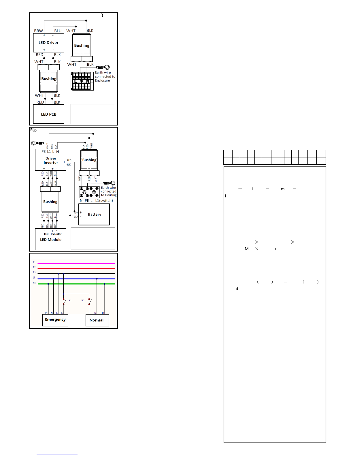
Fig.3 Wiring diagram(Normal version
)
))
)
Fig.4 Wiring diagram(Emergency version)
10. Maintenance/Servicing
10.1 General
The relevant national regulations which apply to the
aintenance/servicing of electrical apparatus in
explosive at ospheres, shall be observed (IEC/EN
60079-17). The interval between aintenance
depends upon the a bient conditions and the hours
of operation. The reco endations given within IEC
60079-17 for recurring checks ust be observed.
10.2 Checks
The equipment must be de-energised before opening
Visual inspection should be carried out at a ini u
of 12 onthly intervals and ore frequently if
conditions are severe, refer to IEC/EN 60079-17. The
ti e between la p changes could be very infrequent
and this is too long a period without inspection.
10.3 Routine Examination
During aintenance, the parts affecting the level of
protection ust be checked in particular:
- Ensure the la p is lit when energised and exa ine
the enclosure and glass for any signs of cracks and
da age.
- When de-energised and left to cool, there should be
no significant sign of internal oisture. If there are
signs of water ingress, the lu inaire should be opened
up, dried out, and any likely ingress points eli inated
by re-gasketing, re-greasing or other replace ent.
- Check the gasket of ter inal cha ber gasket and LED
housing for any da age or per anent set and replace
as required.
- To aintain the light output, clean the protective
glass periodically with a da p cloth or a ild cleaning
fluid.
- If this product is used in the co bustible dust area,
outside of enclosure ust be cleaned on a regular
basis to prevent accu ulation of dust.
- Ter inal, screw glands and blanking plugs for secure
fitting.
- The ter inal cha ber should be opened periodically
and checked for oisture and dirt ingress. The cable
connections should be checked for tightness. The
gasket should be checked for cracks or lack of
elasticity, and if necessary, replaced. Cover bolt
torque: 1.5~2N .
- The fla eproof path can not be readily checked, it
will not go out of shape.
- The battery should be charged and discharged once
every 6 onths.
- Check that ountings are secure and the adjusting
bolts are tight.
- If it has been suspected that the lu inaire has
echanical da age, a stringent workshop overhaul
will be required. Where spares are needed, these ust
be replaced with factory specified parts.
No odifications should be ade without the
knowledge and approval of the anufacturer.
Cleaning the rests of grease and corrosion do not use
sharp metallic devices that can damage the threads of
the joint, and greasing them using appropriate grease
terminally and chemically stable with a drop
point≥200
℃
like e.g.: HTL lubricant from Cooper
Crouse-Hinds! When the housing need to be repainted,
pay attention that the flameproof joints test without
any part with coating!
11. Repair/Overhaul/Modifications
11.1 General
The national regulations E /IEC60079-19 have to be
observed! Repairs and overhaul may only be carried
out with genuine Cooper Crouse-Hinds spare parts.
Before replacing or disasse bling individual parts,
observe the following:
Disconnect the power supply to the equipment before
maintenance/repair.
Make sure that there is no explosive atmosphere
when opening the equipment. See section 8.4 for
notes on opening and closing the la p.
Battery pack replacement:
In the case of battery failure, the battery pack ust be
replaced as a co plete unit fro the anufacturer.
First, open the cover, then change the failure battery,
last, close the cover.
Only use original spare parts. If the luminaire was
previously in operation then wait to cool enough
before opening. Repairs that affect the explosion
protection, may only be carried out by Cooper
Crouse-Hinds or a qualified electrician in compliance
with the applicable national rules. Modifications to
the device or changes to its design are not permitted.
After carrying out repair or overhaul work, ensure
that the “Exde" properties have not been affected.
Assistance may also be obtained through Cooper
Electronic Technologies (Shanghai) Co., Ltd. Sales
Service department,
955 ShengLi Road, Pudong Shanghai 201201
Phone (86) 21-28993943
12. Disposal/Recycling
When the apparatus is disposed of, the respective
national regulations on waste disposal will have to be
observed.
The charging conductor L1 and the luminaire’s
mains connection must always be connected
to the same external conductor of the mains
supply!
See Fig.2, Fig.3 Fig.4 and Fig. for details.
9. Putting into operation
Prior to putting the apparatus into operation,
the tests specified in the relevant national
regulations shall be carried out. Insulation
easure ents ay only be carried out
between PE and the external conductor L1 (L2,
L3) as well as between PE and N.
- Measure ent voltage: Max. 1 KV AC/DC
- Measure ent current: Max.10 A
- The lu inaire ay only be operated when
closed.
- It is generally reco ended (see IEC/EN
60079-14) that you ensure the type of
protection of the construction is not i paired
during installation.
(1). HPL — Indicates basic catalog series designation.
(2). Indicates Total Lu inous Flux.
-3L—3000L , -4L—4000L , -5L—5000L
-6L
-
6000L , -7L
-
7000L , -8L
-
8000L
(3). Indicates LED colour te perature.
Default — 5700K, -W — 3000K
(4). Indicates Optics type.
Default — Type V optic standard
(5). Indicates ballast voltage.
Default — 100-240V AC 50/60Hz, 108-250V DC
(6). Indicates entry type and size.
-1M — M20
×
1.5, -2M — M25
×
1.5
-D1 — M25
×
1.5(only use for Direct entry)
(7). Indicates Entry quantity.
Default — One entry, -S886 — Dual entry
(8). Indicates Ter inal:
-T1—Pillar ter inal, -T2—MK 6/3, -T3— MK 6/6,
-T4—MUT 4
(
3 pole
)
, -T5—MUT 4
(
6 pole
)
(9). Indicates Glass
Default—Clear Glass, -F—Foggy Glass
(10). Indicates Entry Acc.
Default—No entry acc, -1P—two entries with 1 Plug
-2G—all entries, with plastic cable gland
-3G—two entries, with 1 plastic plug, 1 cable gland
(11). Indicates Mounting Type.
Default—G3/4 Pendant ount only
-B1—With Painted bracket ount only
-B2—with 304SST bracket ount only
-B3—with 316SST bracket ount only
-B4—with both Painted bracket ount,
also available for G3/4 Pendant ount
-B5—with both 304SST bracket ount,
also available for G3/4 Pendant ount
-B6—with both 316SST bracket ount,
also available for G3/4 Pendant ount
-B7—G3/4 Pendant ount, also with ounting
bracket hole cut, but bracket need to order separated.
-B8—only with ounting bracket hole cut,
ounting bracket need to be ordered separated.
(12). E ergency duration
Default—Nor al version
EM1—1.5H, 30% output; EM2—3H, 15% output;
13. Catalog No. definition
HPL -3L -W -1M -S886 * * * * *
(1) (2) (3) (4) (5) (6) (7) (8) (9) (10) (11) (12)
Fig. Wiring diagram
For version with cable
Brown: L
Blue:
Black: L1
Yellow/Green: Ground
For version with cable
Brown: L
Blue:
Yellow/Green: Ground