LIST OF ILLUSTRATIONS EATON 2075
iv
1-1
2-1
2-2
2-3
2-4
2-5
3-1
3-2
3-3
3-4
3-5a
3-5b
3-6
3-7a
3-7b
3-8a
3-8b
3-9a
3-9b
3-lOa
3-lOb
3-lla
3-1
lb
3-12a
3-12b
3-13a
3-13b
3-14a
3-14b
3-15a
3-15b
3-16
3-17
3-18
3-19
3-20
3-21
3-22
3-23
3-24
3-25
LIST OF ILLUSTRATIONS
Title
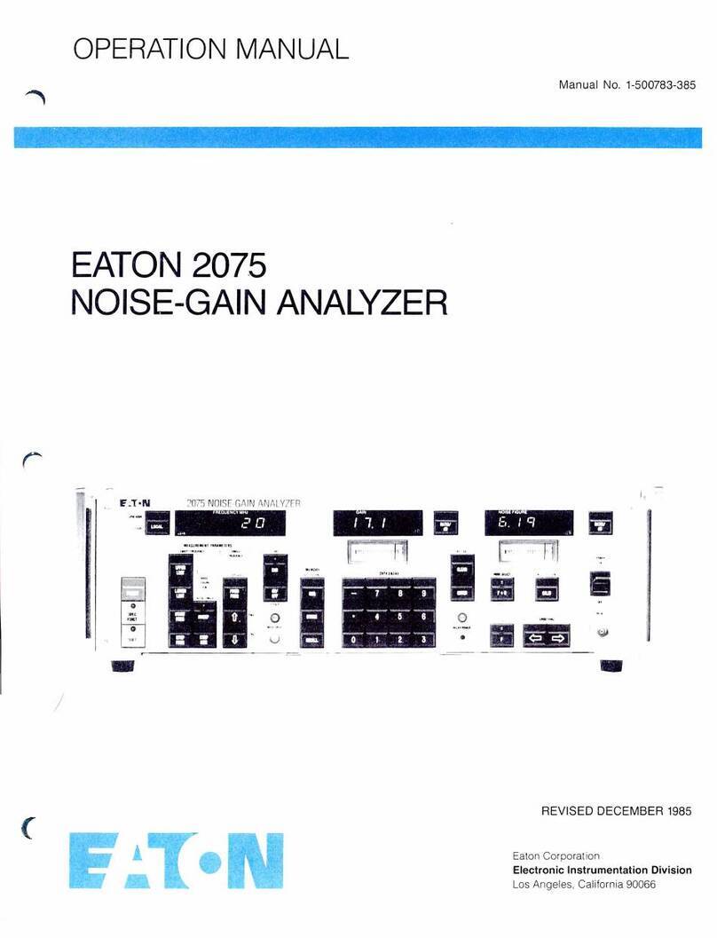
Eaton 2075 Noise Gain Analyzer
........................................
.
AC Voltage Selection Card
.............................................
.
Extemal Relay Voltage Selection
........................................
.
Installation
of
Rack Mounts
............................................
.
Installation
of
Slide Mounts
............................................
.
GPIB Connector
.....................................................
.
Front Panel Controls and Indicators
......................................
.
Rear Panel Controls and lndicators
......................................
.
Uncorrected and Corrected Measurements
................................
.
Test Configuration Downconversion Modes
...............................
.
Test Configuration
1-
Calibration
.......................................
.
Test Configuration
1-
Extemal Relays for Calibration
.......................
.
Test Configuration 1- Extemal Relays for Calibration
.......................
.
Test Configuration 2- Calibration-Double Sideband
.......................
.
Test Configuration
2-
Measurement-
Double Sideband
......................
.
Test Configuration 2
-Calibration
-Single Sideband
........................
.
Test Configuration 2- Measurement-Single Sideband
......................
.
Test Configuration 3
-Calibration
.......................................
.
Test Configuration 3- Measurement
.....................................
.
Test Configuration 4 - Calibration-Double Sideband
.......................
.
Test Configuration
4-
Measurement-Double Sideband
......................
.
Test Configuration
4-
Calibration-Single Sideband
........................
.
Test Configuration 4 -
Measurement-
Single Sideband
......................
.
Test Configuration 5
-Calibration
.......................................
.
Test Configuration 5- Measurement
.....................................
.
Test Configuration
6-
Calibration
.......................................
.
Test Configuration
6-
Measurement
.....................................
.
T0P
Setup-Calibration
................................................
.
T
~P
Setup-
Measurement
..............................................
.
ENR
Setup-Calibration
...............................................
.
ENR
Setup-Measurement
.............................................
.
Manual Y-Factor Measurement
..........................................
.
Example
of
Calibrated Noise Source Data
.................................
.
ENR
Table
1,
2,
or
3
..................................................
.
Setup With Extemal Relays for Calibration
................................
.
Example 1 Sideband Selection
..........................................
.
Example 2 Sideband Selection
..........................................
.
Example 3 Sideband Selection
..........................................
.
Example 4 Sideband Selection
..........................................
.
Bandwidth Compensation Example 1
.....................................
.
Bandwidth Compensation Example 2
.....................................
.
1-1
2-2
2-4
2-5
2-6
2-8
3-4
3-15
3-25
3-30
3-31
3-31
3-31
3-34
3-34
3-38
3-38
3-42
3-42
3-46
4-36
3-50
3-50
3-54
3-54
3-58
3-59
3-64
3-64
3-66
3-66
3-69
3-71
3-73
3-76
3-79
3-80
3-81
3-81
3-82
3-83
