1/12
Instruction Leaflet
Montageanweisung
Notice dinstallation
Instrucciones de montaje
Istruzioni per il montaggio
安
安装说明装说明
Инструкция по монтажу
Montagehandleiding
Montagevejledning
Οδηγίες εγκατάστασης
Instruções de montagem
Monteringsanvisning
Asennusohje
Návod k montái
Paigaldusjuhend
Szerelésiutasítás
Montāasinstrukcija
Montavimo instrukcija
Instrukcja montażu
Navodila za montao
Návod na montá
Монтажни инструкции
Instrucţiuni de montaj
Upute za montau
Montaj talimatı
Інструкція з монтажу
تتﺎﺎــــــــــﻤﻤﻴﻴﻠﻠﻌﻌﺘﺘﻟﻟااررﻮﻮــــــــــﺸﺸﻨﻨﻣﻣ
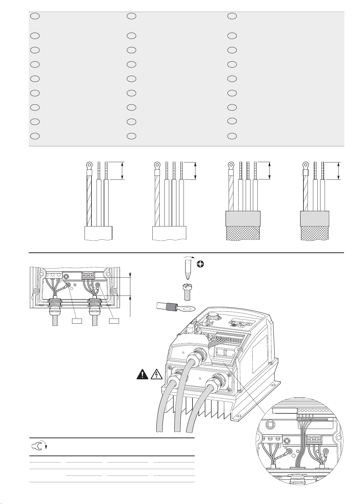
Electric current! Danger to life!
Only skilled or instructed persons may
carryout thefollowing operations.
Lebensgefahr durchelektrischenStrom!
Nur Elektrofachkräfte und elektrotechnisch
unterwiesene Personen dürfen die im Folgenden
beschriebenen Arbeiten ausführen.
Tension électrique dangereuse !
Seules lespersonnes qualifiées et averties doivent
exécuter les travaux ci-après.
¡Corriente eléctrica! ¡Peligro de muerte!
El trabajo a continuación descrito debe ser realizado
por personas cualificadas y advertidas.
Tensione elettrica: Pericolo di morte!
Solo persone abilitate equalificatepossonoeseguire
le operazioni di seguito riportate.
触触电电危危险险!!
只允许专业人员和受过专业训练的人员进行下列工作。
Электрическийток! Опасно дляжизни!
Только специалисты или проинструктированные
лица могут выполнять следующиеоперации.
Levensgevaar door elektrische stroom!
Uitsluitend deskundigen in elektriciteit en
elektrotechnisch geïnstrueerdepersonen is het
toegestaan, de navolgend beschreven
werkzaamheden uittevoeren.
Livsfare på grund af elektrisk strøm!
Kun uddannede el-installatører og personer der
e instruerede i elektrotekniske arbejdsopgaver,
må udføre de nedenfor anførte arbejder.
Προσοχή, κίνδυνοςηλεκτροπληξίας!
Οι εργασίες που αναφέρονται στη συνέχειαθα
πρέπει να εκτελούνται μόνο από ηλεκτρολόγους
και ηλεκτροτεχνίτες.
en
de
fr
es
it
zh
ru
nl
da
el
Perigo de vida devido a corrente eléctrica!
Apenas electricistas epessoas comformação
electrotécnica podem executaros trabalhos
que a seguir se descrevem.
Livsfara genom elektrisk ström!
Endast utbildade elektrikeroch personer som
undervisats i elektroteknik får utföra de arbeten
som beskrivs nedan.
Hengenvaarallinen jännite!
Vain pätevät sähköasentajat ja opastusta saaneet
henkilöt saavatsuorittaa seuraavat työt.
Nebezpečí úrazu elektrickým proudem!
Níe uvedené práce smějí provádět pouze
osoby s elektrotechnickým vzděláním.
Eluohtlik! Elektrilöögioht!
Järgnevalt kirjeldatud töid tohib teostada ainult
elektriala spetsialist vői elektrotehnilise
instrueerimise läbinud personal.
Életveszély az elektromos áramrévén!
Csakelektromos szakemberek és
elektrotechnikában képzett személyek
végezhetik el a következőkben leírt munkákat.
Elektriskā strāva apdraud dzīvību!
Tālāk aprakstītos darbus drīkst veikt tikai
elektrospeciālisti un darbam ar elektrotehniskām
iekārtām instruētās personas!
Pavojus gyvybei dėl elektrossrovės!
Tik elektrikaiir elektrotechnikos specialistai gali
atlikti emiau apraytus darbus.
Porażenie prądem elektrycznym stanowi
zagrożeniedla życia!
Opisane poniżej pracemogą przeprowadzać tylko
wykwalifikowani elektrycy oraz osoby odpowiednio
poinstruowane w zakresie elektrotechniki.
pt
sv
fi
cs
et
hu
lv
lt
pl
ivljenjska nevarnost zaradi
električnega toka!
Spodaj opisana dela smejo izvajati samo
elektrostrokovnjaki in elektrotehnično
poučene osebe.
Nebezpečenstvo ohrozenia ivota
elektrickým prúdom!
Práce, ktoré sú niieopísané, smú vykonávat iba
elektroodborníci a osoby s elektrotechnickým
vzdelaním.
Опасност за живота от електрически ток!
Операциите, описани в следващите раздели,
могат да се извършват само от
специалисти-електротехници и инструктиран
електротехнически персонал.
Atenţie! Pericol electric!
Toate lucrările descrise trebuie efectuate numai
de personal de specialitate calificat şi de persoane
cu cunoştiinţeprofunde în electrotehnică.
Opasnost po ivot uslijed električne struje!
Radove opisaneunastavku smiju obavljati samo
stručni električari i osobe koje su prole
elektrotehničkuobuku.
Elektrik akımı! Hayati tehlike!
Aşağıdaki işlemleri yalnızca kalifiye veya eğitimli
kişiler gerçekleştirebilir.
Електричний струм! Небезпечнодля життя!
Виконувати означені далі операції дозволяється
тільки кваліфікованим особам, що пройшли
інструктаж.
تتﻮﻮــــﻣﻣﺮﺮــــﻄﻄﺧﺧ!!ﻲﻲﺋﺋﺎﺎــــﺑﺑﺮﺮﻬﻬﻛﻛررﺎﺎــــﻴﻴﺗﺗ!!ﺮﺮﻳﻳﺬﺬــــﺤﺤﺗﺗ!!
ﺐـــــﻴﻛﺮﺘﻟا و ﺔﻧﺎﻴـــــﺼﻟا لﺎـــــﻤﻋا ﻢـــــﺘﺗ ﻻ
ﻦﻴﺑرﺪــــﻤﻟا ﻦﻴﻠﻣﺎــــﻌﻟا ﻞــــﺒﻗ ﻦــــﻣ ﻻا !
sl
sk
bg
ro
hr
tr
uk
ar
04/21 IL040059ZU
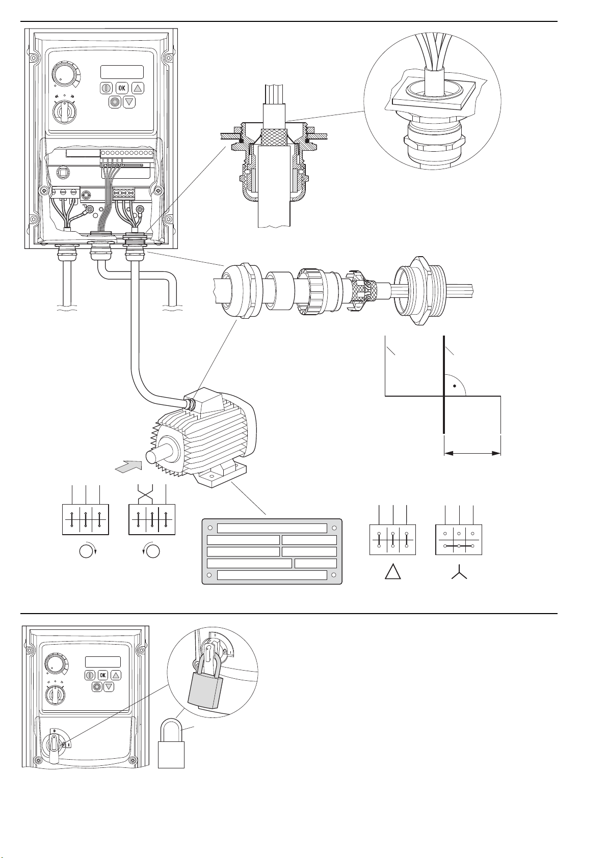
DC1-1D-A6OE1
DC1-12-A6OE1
DC1-32-A6OE1
DC1-34-A6OE1
DC1--A6S
FS1, FS2, FS3, FS4
IP66, NEMA 4x
DC1--A66
FS1, FS2, FS3, FS4
IP66, NEMA 4x
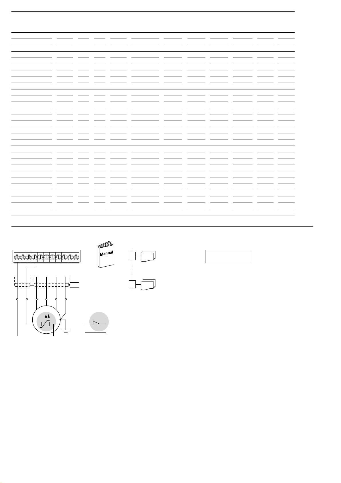
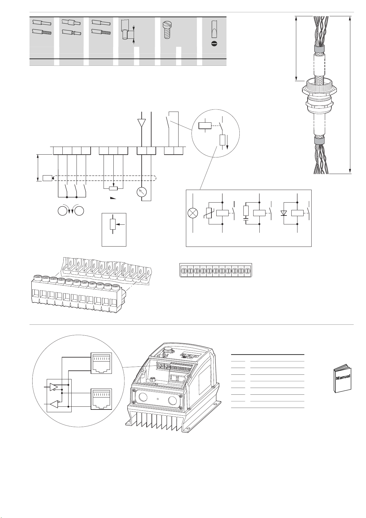
Eaton.com/documentation
MN040059 DC1
Eaton.com/EcoDesign-VFD
MZ040046EN
→