manuals.online logo
Brands
  1. Home
  2. •
  3. Brands
  4. •
  5. Eaton
  6. •
  7. Media Converter
  8. •
  9. Eaton ELC-AN06AANN User manual

Eaton ELC-AN06AANN User manual

IL05003003E.pdf
5011629903-A603
2007-05-08
ELC-AN06AANN
Analog to Digital/Digital to Analog
Converter Mixed Module
Instruction Sheet
WARNING
•This Instruction Sheet only provides descriptions for electrical specifications, general
specifications, installation & wiring, troubleshooting and peripherals. For more information about
the optional peripherals, please see ELC Application Manual.
•This is an OPEN TYPE Controller. The ELC should be kept in an enclosure away from airborne
dust, humidity, electric shock risk and vibration. Also, it is equipped with protective methods
such as some special tools or keys to open the enclosure, so as to avoid the hazard to users
and the damage to the ELC. Do NOT touch terminals when power on.
•Never connect the AC main circuit power supply to any of the input/output terminals, as it will
damage the ELC. Check all the wiring prior to power up. To avoid any electromagnetic noise,
make sure the ELC is properly grounded .
•Warning – Do not disconnect while circuit is live unless area is known to be non-hazardous.
•Power, input and output (I/O) wiring must be in accordance with Class 1, Div. 2 wiring methods -
Article 501-10(B)(1) of the National Electrical Code.
•Suitable for use in Class 1, Division 2, Groups A, B, C, D or Non-Hazardous locations only.
•Warning – Explosion hazard - Substitution of components may impair suitability for Class 1,
Division 2.
•Warning – Explosion Hazard - Do not disconnect equipment unless power has been switched
off or the area is known to be Non-Hazardous.
1 INTRODUCTION
1.1 Model Explanation and Peripherals
Thank you for choosing Eaton Logic Controller (ELC) series products. The ELC-AN06AANN allows
the connection of four analog inputs and 2 groups 12 bits digital outputs (voltage/current). The ELC
transforms the input into a 12 bit digital signal and the output into a 2 points analog signal, which may
then be manipulated using TO and FROM commands in the ladder logic program. There are 49
Controlled Registers (CR) in each module (each register is 16 bits). The Analog Input/Output Mixed
Module of ELC-AN06AANN can read/write the data of analog input module by using commands
FROM / TO via ELC program.
1.2 Product Profile and Outline
EXTENSION
PORT
25.2
3
M
C
H
1
POWER
ERROR
AD
M
C
H
6
C
H
5
M
C
H
4
M
C
H
3
M
C
H
2
90
ELC-AN06AANN
3
M
60
12
56
4
8
3
2
1
3
11
8
7
13 14
9
Units: mm
1. Status indicator (Power, RUN and ERROR) 2. Model Name
3. Extension unit clip 4. Input/output terminal
5. DIN rail clip 6. Mounting hole of the extension unit
7. Nameplate 8. Extension unit clip
9. DIN rail (35mm) 10. Extension port
11. RS-485 Communication port 12. 2 pin
r
emovable terminal (standard accessory)
13. DC power input 14. Power input cable (standard accessory)
1.3 External Wiring
CH1
100K
250
-10V~+10V
V+
I+
COM
CH1
100K
CH4
100K
250
-20mA~+20mA V+
I+
COM
CH4
100K
*3
*2
AG
AG
Current input
Voltage input
Shielded*1
Shielded*1
Note 1: Please isolate analog input and
other power wiring.
Note 2: If input connected current signal,
please short circuit between V+ and I+
terminals.
Note 3: If wave of input terminal of loaded
is too big that noise interferes wiring,
please connect capacitance with
0.1~0.47μF 25V.
Voltage output
0V ~ 10
V
V+
*5
@
FG
COM
V+
FG
I+
CH1
CH2
24+
24- AG
+15V
-15V
DC/DC
converter
*6
@
System
Grounding
Class 3 Grounding
(100 or less)
Ω
DC24V
I+
Current output
0mA~20m
A
COM
CH5
CH6
Isolation wire 4¡@
*
Isolation wire 4¡@
*
AC drive, recorder,
scale valve...
AC drive, recorder,
scale valve...
terminal of
power module
Note 4: Please isolate analog output and
other power wiring.
Note 5: If wave of output terminal of loaded
is too big that noise interferes wiring,
please connect capacitance with
0.1~0.47μF 25V.
Note 6: Please connect terminal of
power module and terminal of analog
output module to system earth point and
make system earth point be grounding or
connects to machine cover.
Warning: DO NOT wire to the No function
terminal. Use Copper Conductor Only,
60/75 °C.
2 STANDARD SPECIFICATIONS
2.1 Specifications
FOUR CH. (A/D) CONVERTER VOLTAGE INPUT CURRENT INPUT
Power Supply Voltage 24 VDC(20.4VDC~28.8VDC) ( –15%~+20%)
Analog Input Channel 4 channels per module
Analog Output Range ±10V ±20 mA
Digital Data Range ±2,000 ±1,000
Resolution 12 bits(1LSB=5 mV) 11 bits (1LSB=20 μA)
Input Impedance 200 KΩand above 250Ω
Overall Accuracy
±0.5% of full scale of 25℃(77℉)
±1% of full scale during 0~55℃(32~131℉)
Response Time 3 ms ×channels
Isolation Method There is no Isolation between digital and analog circuitry.
Isolation Field to Digital Area: 500V Field to Analog Area: 500V
Analog area to Digital Area: 500V Field to 24VDC: 500V
Absolution Input Range ±15 V ±32 mA
Digital Data Format 2’s complement of 16-bit, (11 Significant Bits)
Average Function Yes (CR#2~CR#5 can be set and the range is K1~K100)
Self Diagnostic Function Self Detection Upper bound and lower bound detection per channel
TWO CH. D/A CONVERTER VOLTAGE OUTPUT CURRENT OUTPUT
Analog Signal Output Channels 2 channel per module
Analog Output Range 0~10V 0~20 mA
Digital Data Range 0~4,000 0~4,000
Resolution 12 bits (1LSB=2.5 mV) 12 bits (1LSB=5 μA)
Output Impedance 0.5Ωor lower
Overall Accuracy ±0.5% of full scale at 25℃(77℉)
±1% of full scale during 0~55℃(32~131℉)
Response Time 3 ms ×Channels
Max. Output Current 10 mA(1KΩ~2MΩ) -
Tolerance Carried Impedance -0~500Ω
Digital Data Format 2’s complement of 16-bit, (11 Significant Bits)
Isolation Method There is no Isolation between digital and analog circuitry.
Isolation Field to Digital Area: 500V Field to Analog Area: 500V
Analog area to Digital Area: 500V Field to 24VDC: 500V
Protection Voltage output has short circuit protection but short circuit for a long
time may cause inner wiring damage and open circuit protection.
Communication Mode (RS-485)
MODBUS ASCII/RTU Mode. Communication baud rate of 4,800 / 9,600
/ 19,200 / 38,400 / 57,600 / 115,200 bps. For ASCII mode, date format
is 7Bits, even, 1 stop bit (7 E 1). For RTU mode, date format is 8Bits,
even, 1 stop bit (8 E 1). The RS-485 is disabled when the
ELC-AN06AANN is connected in series to an ELC.
Connect to ELC MPU in Series
When ELC-AN06AANN modules are connected to an ELC, the
modules are numbered from 0 - 7. 0 is the closest to the MPU and 7 is
the furthest. The Maximum number of modules is 8 modules and they
TWO CH. D/A CONVERTER VOLTAGE OUTPUT CURRENT OUTPUT
do not occupy any digital I/O points of the MPU.
2.2 Other Specifications
Maximum Power Consumption 2W at 24 VDC (20.4VDC~28.8VDC) ( -15 % ~ +20 %)
Noise Immunity
ESD(IEC 61131-2, IEC 61000-4-2): 8KV Air Discharge
EFT(IEC 61131-2, IEC 61000-4-4): Power Line: 2KV, Digital I/O: 1KV,
Analog & Communication I/O: 1KV
RS(IEC 61131-2, IEC 61000-4-3): 26MHz~1GHz, 10V/m
Grounding
The diameter of the grounding wire cannot be smaller than that of
terminals 24V and 0V (if numerous ELCs are used at the same time,
make sure that each ELC is grounded respectively to the ground poles)
Vibration/Shock Immunity International Standard Regulations: IEC61131-2, IEC 68-2-6 (TEST Fc)/
IEC61131-2 & IEC 68-2-27 (TEST Ea)
Operation/Storage Environment Operation: 0 ℃~55 ℃(temperature), 50~95% (humidity), pollution
degree: 2; Storage: -25℃~70℃(temperature), 5~95% (humidity)
Agency Approvals
UL508
UL1604, Class1,Div2 Operating temperature code: T5
European community EMC Directive 89/336/EEC and Low Voltage
Directive 73/23/EEC
3CR(CONTROLL REGISTER)
ELC-AN06AANN EXPLANATION
CR
No
Parameter
Comm.
address
Latched Register Name b15 b14 b13 b12 b11 b10 b9 b8 b7 b6 b5 b4 b3 b2 b1 b0
#0 H 40C8 O R Model type Data length is 8 bits (b7~b0). ELC-AN06AANN model code= H CC
#1 H 40C9 O R/W
Mode setting
CH6 CH5 CH4 CH3 CH2 CH1
Input mode setting: (CH1~CH4)
Mode 0: input voltage mode (-10V~+10V). Factory Setting is H0000.
Mode 1: input voltage mode (-6V~+10V).
Mode 2: input current mode (-12mA~+20mA).
Mode 3: input current mode (-20mA~+20mA).
Mode 4: Reserved
Output mode setting: (CH5~CH6)
Mode 0: output voltage mode (0V~10V).
Mode 1: output voltage mode (2V~10V).
Mode 2: output current mode (4mA~20mA).
Mode 3: output current mode (0mA~20mA).
#2 H 40CA O R/W
CH1 average
number
Average numbers setting of channel CH1~CH4. Setting range is K1~K100 and
factory setting is K10.
#3 H 40CB O R/W
CH2 average
number
#4 H 40CC O R/W
CH3 average
number
#5 H 40CD O R/W
CH4 average
number
#6 H 40CE X R
Average value of
CH1 input signal
Display average value of CH1~CH4 input signal
#7 H 40CF X R
Average value of
CH2 input signal
#8 H 40D0 X R
Average value of
CH3 input signal
#9 H 40D1 X R
Average value of
CH4 input signal
#10 H 40D2 X R/W
CH5 output
signal value Output value of CH5~CH6, the setting range is K0~K4,000. The factory setting is
K0 and the unit is LSB.
#11 H 40D3 X R/W
CH6 output
signal value
#12 H 40D4 X R
Present value of
CH1 input signal
Display present value of CH1~CH4 input signal
#13 H 40D5 X R
Present value of
CH2 input signal
#14 H 40D6 X R
Present value of
CH3 input signal
#15 H 40D7 X R
Present value of
CH4 input signal
#16~ #17 Reserved
#18 H 40DA O R/W
To adj. OFFSET
value of CH1
Offset setting of CH1~CH4. Factory setting is K0 and unit is LSB.
Voltage input: setting range is K-1,000 ~K1,000
Current input: setting range is K-1,000 ~K1,000
#19 H 40DB O R/W
To adj. OFFSET
value of CH2
#20 H 40DC O R/W
To adj. OFFSET
value of CH3
#21 H 40DD O R/W
To adj. OFFSET
value of CH4
#22 H 40DE O R/W
To adj. OFFSET
value of CH5 Offset setting of CH5~CH6. Factory setting is K0 and unit is LSB.
The setting range is K-2,000~K2,000
#23 H 40DF O R/W
To adj. OFFSET
value of CH6
#24 H 40E0 O R/W
To adj. GAIN
value of CH1 GAIN setting of CH1~CH4. Factory setting is K1,000 and unit is LSB.
IL05003003E.pdf
ELC-AN06AANN EXPLANATION
#25 H 40E1 O R/W
To adj. GAIN
value of CH2 Voltage input: setting range is K-800 ~K4,000
Current input: setting range is K-800 ~K2,600
#26 H 40E2 O R/W
To adj. GAIN
value of CH3
#27 H 40E3 O R/W
To adj. GAIN
value of CH4
#28 H 40E4 O R/W
To adj. GAIN
value of CH5 GAIN setting of CH5~CH6. Factory setting is K2,000 and unit is LSB.
The setting range is K-1,600~K8,000
#29 H 40E5 O R/W
To adj. GAIN
value of CH6
#30 H 40E6 X R Error status Data register stores the error status, refer to fault code chart for details.
#31 H 40E7 O R/W
Communication
address setting
RS-485 communication address.
Setting range is K1~K255 and factory setting is K1
#32 H 40E8 O R/W
Communication
baud rate setting
Communication baud rate (4,800, 9,600, 19,200, 38,400, 57,600 and 115,200 bps).
For ASCII mode, date format is 7Bits, even, 1 stop bit (7,E,1). For RTU mode, date
format is 8Bits, even, 1 stop bit (8, E,1).
b0: 4,800 bps (bit/sec), b1: 9,600 bps (bit/sec). (factory setting)
b2: 19,200 bps (bit/sec), b3: 38,400 bps (bit/sec).
b4: 57,600 bps (bit/sec), b5: 115,200 bps (bit/sec).
b6~b13: Reserved, b14: switch between low bit and high bit of CRC code (only for
RTU mode), b15: RTU mode.
#33 H 40E9 O R/W
Reset to factory
setting and set
characteristics
adjustable
priority
b15 b14 b13 b12 b11 b10 b9 b8 b7 b6 b5 b4 b3 b2 b1 b0
CH6 CH5 CH4 CH3 CH2 CH1
Example: Setting of CH1
1. When b0=0, user can set OFFSET and GAIN value of CH1 (CR#18, CR#24).
When b0=1, inhibit user to adjust OFFSET and GAIN value of CH1.
2. b1 means if characteristic register is latched. b1=0 (factory setting, latched),
b1=1 (not latched).
3. b2: Set to 1 and ELC-AN06AANN will be reset to factory settings.
The setting of CH5~CH6, give CH5 setting for example: b13, b12:
00: can be adjusted, latched, 01: can be adjusted, non-latched.
10: inhibit adjust, 11: reset to factory settings and clear b12, b13 to 0.
#34 H 40EA O R System Version Display software version in hexadecimal. Example: H 010A = version 1.0A.
#35~#48 System used
O means latched. X means non-latched.
R means can read data by using FROM command or RS-485. W means can write data by using TO command or RS-485.
LSB (Least Significant Bit): 1. Voltage input: 1LSB=10V/2,000=5mV. 2. Current input: 1LSB=20mA/1,000=20μA.
3. Voltage output: 1LSB=10V/4,000=2.5mV. 4. Current output: 1LSB=20mA/4,000=5μA.
Explanation:
1. CR#0: The ELC model type.
2. CR#1: b11~b0 is used to set 4 inner channels working mode of analog input module (AD).
b12~b15 is used to set 2 channels working mode of analog output module (DA). Every channel
has four modes to set and can be set individually. For example: if setting CH1 to mode 0
(b2~b0=000), CH2 to mode 1(b5~b3=001), CH3: mode2 (b8~b6=010), CH4: mode
3(b11~b9=011). It needs to set b0~b11 to H688. If setting CH5: mode 2 (b13~b12=10), CH6:
mode 1 (b15~b14=01), it needs to set b12~b15 to H5. The factory setting is H0000.
3. CR#2 ~ CR#5: Used to set the number of input readings used for the average temperature
calculation. The available range is K1~K100 and factory setting is K10.
4. CR#6 to CR#9: they are used to save the average value of input signal of CH1~CH4.
5. CR#10 ~ CR#11 are used to set the output value of CH5 and CH6. The setting range is
K0~K4,000. The factory setting is K0 and unit is LSB.
6. CR#12 ~ CR#15: they are used to save the present value of input signal of CH1~CH4.
7. CR#16, CR#17, CR#28, CR#29 are reserved.
8. CR #18~ CR #21: the content is the value of adjusting OFFSET value of CH1~CH4 if analog
input voltage or current is 0 after it transfers from analog to digital. Voltage setting range:
-5V~+5V(-1,000LSB~+1,000LSB). Current setting range: -20mA~+20mA (-1,000LSB~+1,000LSB).
9. CR #22~ CR #23: the content is the value of adjusting OFFSET value of CH5~CH6 if analog
input voltage or current is 0 after it transfers from analog to digital. The factory setting is K0 and
the unit is LSB. The setting range is -2,000~+2,000. Voltage setting range:
-5V~+5V(-2,000LSB~+2,000LSB). Current setting range: -10mA~+10mA (-2,000LSB~+2,000LSB).
10.CR #24~ CR #27: That is the value of adjust GAIN value of CH1~CH4. That is the value of
analog input voltage or current when conversion value from analog signal to digital is 4,000.
Voltage setting range: -4V~+20V(-800LSB~+4,000LSB). Current setting range: -16mA~+52mA
(-800LSB ~+2,600LSB). But it needs to notice that GAIN VALUE – OFFSET VALUE =
+200LSB~+3,000LSB (voltage) or +200LSB~+1,600LSB (current). When this value under this range,
the resolution of the input signal will be thin and the variation of value will be larger. When this
value exceeds this range, the resolution of input signal will be thick and the variation of value
will be smaller.
11.CR #28~ CR #29: That is the value of adjust GAIN value of CH5~CH6. That is the value of
analog input voltage or current when conversion value from analog signal to digital is 2,000.
Voltage setting range: -4V~+20V(-1,600LSB~+8,000LSB). Current setting range: -8 mA ~+40 mA
(-1,600LSB~+8,000LSB). But it needs to notice that GAIN VALUE – OFFSET VALUE = +400LSB
~+6,000LSB (voltage/current). When this value under this range, the resolution of the input signal
will be thin and the variation of value will be larger. When this value exceeds this range, the
resolution of input signal will be thick and the variation of value will be smaller.
12.CR#30 is fault code. Please refer to the following chart.
Fault description Content b15~b8 b7 b6 b5 b4 b3 b2 b1 b0
Power source abnormal
(Low voltage alarm) K1(H1)
Reserved
0 0 0 0 0 0 0 1
User setting D/A output
exceeds range K2(H2) 0 0 0 0 0 0 1 0
Setting mode error K4(H4) 0 0 0 0 0 1 0 0
Offset/Gain error K8(H8) 0 0 0 0 1 0 0 0
Hardware malfunction K16(H10) 0 0 0 1 0 0 0 0
Digital range error K32(H20) 0 0 1 0 0 0 0 0
Average times setting error K64(H40) 0 1 0 0 0 0 0 0
Command error K128(H80) 1 0 0 0 0 0 0 0
Note: Each fault code will have corresponding bit (b0~b7). Two or more faults may happen at the same
time. 0 means normal and 1 means having fault.
13.CR#31: RS-485 communication address. Setting range is 01~255 and factory setting is K1.
14.CR#32: RS-485 communication baud rate: 4,800, 9,600, 19,200, 38,400, 57,600 and 115,200.
b0:4,800bps, b1:9,600bps (factory setting), b2:19,200bps, b3:38,400 bps, b4:57,600 bps,
b5:115,200 bps, b6~b13: Reserved, b14: switch between low bit and high bit of CRC code (only
for RTU mode) b15: ASCII / RTU mode. For ASCII mode, date format is 7Bits, even, 1 stop bit
(7,E,1). For RTU mode, date format is 8Bits, even, 1 stop bit (8,E,1).
15.CR#33 is used to set the inner function priority. For example: characteristic register. Output
latched function will save output setting in the inner memory before loss power.
16.The corresponding parameters address H 40C8~H 40EA of CR#0~CR#34 can provide user to
read/write data by RS-485.
a) Communication baud rate: 4,800, 9,600, 19,200, 38,400, 57,600, 115,200 bps.
b) Communication format: ASCII mode is 7Bit, even bit, 1 stop bit (7,E,1). Communication
format of RTU mode is 8Bit, even bit, 1 stop bit (8,E,1).
c) Function code: 03H—read data from register. 06H—write a WORD into register.
10H—write many WORDs into register.
4 ADJUST A/D CONVERSION CHARACTERISTIC CURVE
4.1 Adjust A/D Conversion Characteristic Curve of CH1~CH4
Voltage input mode
+2000
+1000
-1000
10V
digital output
Voltag e
input
-2000
-6V-10V
6V5V2V
0
Mode 1
Mod e 0
GAIN
OFFSET
Mode 0 of CR#1: GAIN=5V(1,000LSB), OFFSET=0V (0LSB).
Mode 1 of CR#1: GAIN=6V(1,200LSB), OFFSET=2V (400LSB).
GAIN: Voltage input value when digital output is 1,000.
Setting range is -4V~+20V(-800LSB~ +4,000LSB)
OFFSET: Voltage input value when digital output is 0.
Setting range: -5V~+5V(-1,000LSB ~ +1,000LSB)
GAIN-OFFSET: Setting range is +1V~+15V (+200LSB~ +3,000LSB)
Current input mode:
+1000
Digital output
Current
Input
-1000
-12mA-20mA
4mA
0
Mod e 2
Mode 3
OFFSET
20mA
GAIN
Mode 2 of CR#1: GAIN = 20mA(1,000LSB), OFFSET=4mA (200LSB).
Mode 3 of CR#1: GAIN = 20mA(1,000LSB), OFFSET=0mA (0LSB).
GAIN: Current input value when digital output is +1,000.
Setting range is -16 mA ~+52 mA (-800LSB ~
+2,600LSB)
OFFSET: Current input value when digital output value is 0.
Setting range is -20 mA~+20 mA (-1,000LSB ~
+1,000LSB )
GAIN-OFFSET: Setting range is +4mA ~ +32mA (200LSB~ +1,600LSB)
The chart above is to adjust A/D conversion characteristic curve of voltage input mode and current
input mode. Users can adjust conversion characteristic curve by changing OFFSET values
(CR#18~CR#21) and GAIN values (CR#24~CR#27) depend on application.
Voltage input: 1LSB=10V/2,000=5mV. Current input 1LSB=20mA/1,000= 20μA.
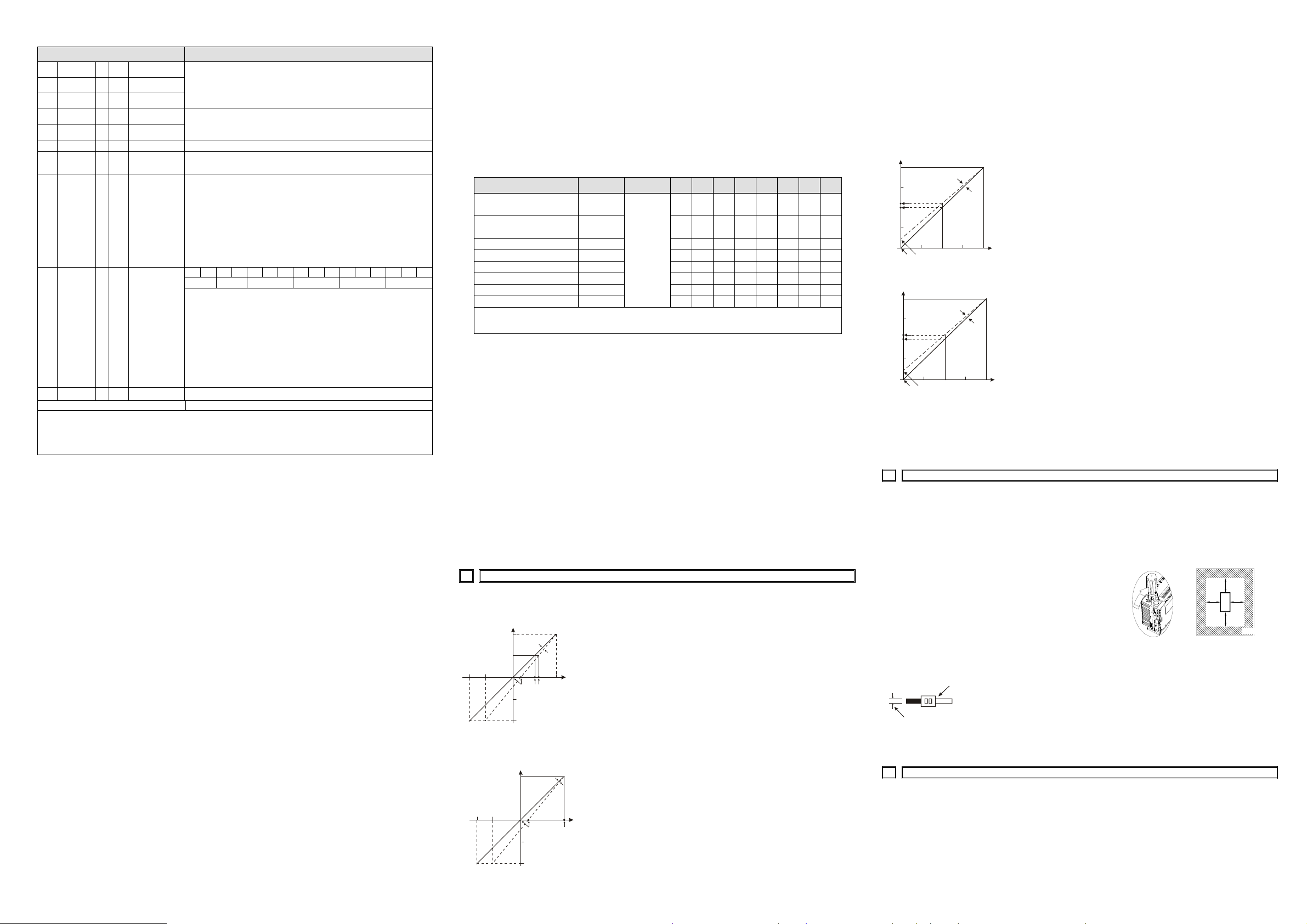
4.2 Adjust D/A Conversion Characteristic Curve of CH5~CH6
Voltage output mode
0+2000 +4000
2V
5V
6V
10V
OFFSET
GAIN
Voltage output
mode 1
mode 0
Digital
input
Mode 0 of CR#1: GAIN = 5V(2,000LSB), OFFSET=0V (0LSB)
Mode 1 of CR#1: GAIN = 6V(2,400LSB), OFFSET=2V (800LSB).
GAIN: Voltage output value when digital input is K2,000.
Setting range is -4V~+20V(-1,600LSB ~+8,000 LSB).
OFFSET: Voltage output value when digital input is K0.
Setting range: -5V~+5V(-2,000LSB ~ +2,000 LSB).
GAIN-OFFSET: Setting range is +1V~+15V(+400LSB ~ +6,000 LSB)
Current output mode:
0+2000 +4000
20mA
OFFSET
GAIN
12mA
10mA
4mA
Current output
Mode 2
Mode 3
Digital
input
Mode 2 of CR#1: GAIN = 12mA(2,400LSB ),OFFSET=4mA (800LSB).
Mode 3 of CR#1: GAIN = 10mA(2,000LSB), OFFSET=0mA (0LSB).
GAIN: Current output value when digital input value is
K2,000. Setting range is -8 mA ~ +40 mA (-1,600LSB
~+8,000LSB).
OFFSET: Current output value when digital input is K0. Setting
range is -10 mA ~ +10 mA (-2,000LSB ~+2,000LSB).
GAIN-OFFSET: Setting range is +2mA~+30mA(+400LSB ~+6,000LSB)
The chart above is to adjust D/A conversion characteristic curve of voltage output mode and current
output mode. Users can adjust conversion characteristic curve by changing OFFSET values
(CR#14~CR#15) and GAIN values (CR#18~CR#19) depend on application.
Voltage output: 1LSB=10V/4,000=2.5mV., Current output: 1LSB=20mA/4,000=5μA.
5INSTALLATION & WIRING
1. Installation of the DIN rail
The ELC can be secured to a cabinet by using the DIN rail that is 35mm high with a depth of 7.5mm.
When mounting the ELC on the DIN rail, be sure to use the end bracket to stop any side-to-side
motion of the ELC, thus to reduce the chance of the wires being pulled loose. At the bottom of the
ELC is a small retaining clip. To secure the ELC to the DIN rail, place it onto the rail and gently push
up the clip.
To remove it, pull down the retaining clip and gently pull the
ELC away from the DIN rail. As shown on the right:
When installing the ELC, make sure that it is installed in an
enclosure with sufficient space (as shown on the right) to its
surroundings so as to allow heat dissipation.
D
D
DD
E
L
C
D>50mm
2. Wiring
22-16AWG
<1.5mm
Notes:
1. Please use 22-16AWG (1.5mm) wiring (either single or multiple
core) for I/O wiring terminals. The specification for the terminals is
as shown on the left. ELC terminal screws should be tightened to
1.95 kg-cm (1.7 lb-in). Use Copper Conductor Only, 60/75 °C.
2. I/O signal wires or power supply should not run through the same
multi-wire cable or conduit.
6INITIAL ELC START-UP
Lamp display:
1. Upon power-up, the ERROR LED will light for 0.5 seconds the POWER LED will light
continuously.
2. No errors= POWER LED on and ERROR LED off.
Low Voltage error (lower than 19.5V), ERROR LED will blink continuously till the power
supply rises above 19.5V.
3. ELC-AN06AANN connected to ELC in series = RUN LED on MPU will be lit and A/D
IL05003003E.pdf
LED or D/A LED should blink.
4. After receiving the first RS-485 command the A/D LED or D/A LED will blink.
5. If the input or output exceeds the upper or lower bounds, then the ERROR LED will
blink.
6. When main ELC and extension unit communicate time-out or abnormal interrupt, LED
ERROR of extension unit will keep lighting.

Other Eaton Media Converter manuals

Eaton Pow-R-Command 1000 BCB Manual

Eaton

Eaton Pow-R-Command 1000 BCB Manual

Eaton DX-SPL-RJ45-3SL Manual

Eaton

Eaton DX-SPL-RJ45-3SL Manual

Eaton DX-CBL-PC-3M0 Manual

Eaton

Eaton DX-CBL-PC-3M0 Manual

Eaton LVLD Series User manual

Eaton

Eaton LVLD Series User manual

Eaton TRIPP LITE Series User manual

Eaton

Eaton TRIPP LITE Series User manual

Eaton DX-COM-PCKIT Manual

Eaton

Eaton DX-COM-PCKIT Manual

Eaton KME6-1875-2 User manual

Eaton

Eaton KME6-1875-2 User manual

Eaton PowerXL User manual

Eaton

Eaton PowerXL User manual

Eaton DC1-1D-A6 OE1 Series Manual

Eaton

Eaton DC1-1D-A6 OE1 Series Manual

Eaton DX-CBL-PC-3M0 Manual

Eaton

Eaton DX-CBL-PC-3M0 Manual

Eaton DXA-EXT-ENCOD Manual

Eaton

Eaton DXA-EXT-ENCOD Manual

Eaton MTL 9475-ETG User manual

Eaton

Eaton MTL 9475-ETG User manual

Eaton DX-SPL-RJ45 Manual

Eaton

Eaton DX-SPL-RJ45 Manual

Popular Media Converter manuals by other brands

Leine Linde MRI 2202 Mounting instructions

Leine Linde

Leine Linde MRI 2202 Mounting instructions

Siemens SINAMICS G120D operating instructions

Siemens

Siemens SINAMICS G120D operating instructions

Rivera FS8M owner's manual

Rivera

Rivera FS8M owner's manual

QYSEA V6 Series user manual

QYSEA

QYSEA V6 Series user manual

Miranda SDM-872p Guide to installation and operation

Miranda

Miranda SDM-872p Guide to installation and operation

Allied Telesis AT-DMC1000/SC installation guide

Allied Telesis

Allied Telesis AT-DMC1000/SC installation guide

tams elektronik WD-34.BiDiB manual

tams elektronik

tams elektronik WD-34.BiDiB manual

Calibre HQView620 operating instructions

Calibre

Calibre HQView620 operating instructions

Siko WH3650M Translation of the original installation instructions

Siko

Siko WH3650M Translation of the original installation instructions

Atlantic 63705079 manual

Atlantic

Atlantic 63705079 manual

Canever AUDIO ZeroUnoPURE DAC operating instructions

Canever

Canever AUDIO ZeroUnoPURE DAC operating instructions

FIAL 2310 AL manual

FIAL

FIAL 2310 AL manual

IntesisBox IBOX-MBS-DALI Installation sheet

IntesisBox

IntesisBox IBOX-MBS-DALI Installation sheet

iLive IBD704 user guide

iLive

iLive IBD704 user guide

Lechpol ZLA0110 quick start guide

Lechpol

Lechpol ZLA0110 quick start guide

Ritron LM-DTMF Programming instructions

Ritron

Ritron LM-DTMF Programming instructions

Siemens 6RA70 Series Faq

Siemens

Siemens 6RA70 Series Faq

Autonics E50 Series product manual

Autonics

Autonics E50 Series product manual

manuals.online logo
manuals.online logoBrands
  • About & Mission
  • Contact us
  • Privacy Policy
  • Terms and Conditions

Copyright 2025 Manuals.Online. All Rights Reserved.