IL17435 Rev. C
Page 1-2 Effective Date: 1/05
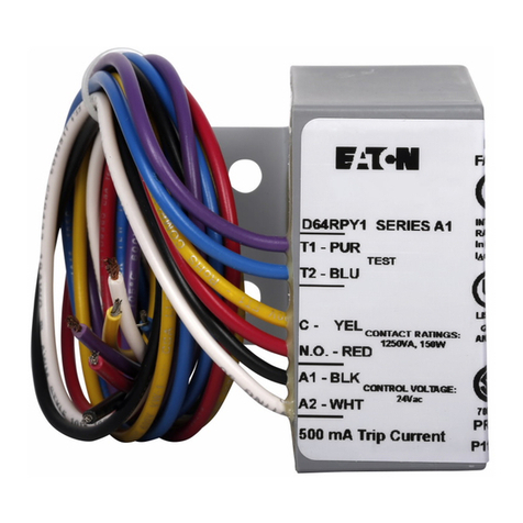
Addressable Relay II
Page 1-2 For more information visit: www.eatonelectrical.com Effective Date: 1/05
block, power requirement is 5 VA. dc polarity is not
significant. The operating temperature range of the
Addressable Relay II is 0o C to 70oC.
Each Addressable Relay II includes two status indicating
circuits (IN1 and IN2) which can be used to transmit the
contact status of devices external to the Addressable
Relay II. A typical installation using these report-back
inputs to the PowerNet system is shown in Figure 2.
Terminals 4 and 5 connect to the status indicating 1
circuit and terminal 6 and 7 connect to the status indicat-
ing 2 circuit. See Figure 1. These status indicating
circuits operate with input voltages of 120 +/-20% Volts
ac or 48 to 125 Volts dc circuits.
The Addressable Relay II includes a feature called the
Communications Watchdog. The communications
watchdog monitors communications between the Addres-
sable Relay II and the computer control station. If com-
munications are lost, the communications watchdog will
reset the relay to the de-energized (OFF) state. The
Addressable Relay II must be updated every 4 seconds
when the communications watchdog is enabled or else
communications are assumed to be lost. The communica-
tions watchdog is enabled when DIP switch 3 is set to the
ON position. When the communications watchdog is not
enabled, the relay will remain in the state set by the last
command issued. See Figure 4 for DIP switch configura-
tion.
The Addressable Relay II also includes a feature called
Relay Pulse which is enabled and disabled by the DIP
switch setting. With the relay pulse feature enabled, the
Addressable Relay II will operate when it receives an ON
signal in the form of a pulse. Having been turned ON by
the pulse signal, the relay will automatically turn itself OFF
after an ON period of 8 to 12 seconds. When DIP switch
2 is set to the OFF position to disable the relay pulse
feature the Addressable Relay II will remain in the state
set by the last command.
Each Addressable Relay II (see Figure 1) has three hexa-
decimal (digits 0 through 9 plus A through F) selector
switches that must be used to assign a unique address to
each unit on the network. The light emitting diode (LED)
at the top left-hand corner of the product (labeled RLY)
illuminates red when the relay is energized and illuminates
green when the relay is de-energized. The LED below
labeled TX flashes when the Addressable Relay II is
transmitting the status of the two report-back inputs into
the PowerNet network.
SECTION 5.0 ADDRESSING
Each Addressable Relay II installed in any one network
must have a unique address. The three hexadecimal
selector switches offer 4096 different addresses (16 x 16
x 16), ranging from 000 to FFF. Records of addresses
may be maintained in terms of the hexadecimal number
(recommended) or decimal equivalent. In a hexadecimal
system, A = 10, B = 11, C = 12, D = 13, E = 14 and
F = 15. Examples of switch settings are shown in Figure
5.
To convert from a hexadecimal number to a decimal
number:
1) Multiply the setting on the top switch (A2) by 256.
2) Multiply the setting on the center switch (A1) by 16.
3) Multiply the setting on the bottom switch (A0) by 1.
4) Add the results from step 1, 2 and 3 together.
The results for the second example in Figure 5 is (2 x
256) + (1 x 16) + 10 = 538.
SECTION 6.0 WIRING
Wire the 12-pole terminal block located on the Address-
able Relay II per Figure 6. The terminal block capabilities
are shown in Section 6.1. Terminal 1, 2 and 3 are used
for the relay output. Terminals 4 and 5 are used for
status indicating circuit 1. Terminals 6 and 7 are used for
status indicating circuit 2. Terminal 10 is not used.
Terminals 11 and 12 are used to supply the control
power. The polarity of the control power is not important.
OFF ON
Baud Rate 9600 1200
Relay Pulse Disabled Enabled
Comm. Watchdog Disabled Enabled
FIGURE 4 DIP SWITCH FUNCTIONS
FIGURE 3 - TYPICAL NETWORK INTERWIRING
