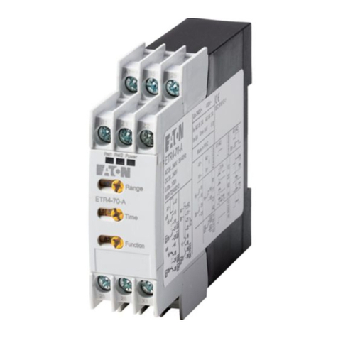
Technical parameters
Switch drop:
Load-B1 terminal connection:
SPDT or DPDT
multifunction red LED
rotary switch
1, AgNi or 2, AgNi
16 A / AC1
30 A / <3 s
4000 VA / AC1, 384 W / DC
250VAC1/24VDC
III.
2
max. 150 ms
500 mW
4 kV (supply - output)
any
IP 40
90x17.6x64mm
EN 61812-1, EN 61010-1
Y
Y
Y
DIN rail EN 60715
Changeover contacts:
Output
Breaking capacity:
Min. breaking capacity DC:
Switching voltage:
Rated current:
Inrush current:
Output indication:
Mechanical life:
Electrical life:
Operating temperature:
Electrical strength:
Mounting/DIN rail:
Overvoltage cathegory:
Storage temperature:
Operating position:
Protection degree:
Pollution degree:
Reset time:
Max. cable size:
Dimensions:
Standards:
Weight:
Number of functions:
Supply:
Supply voltage:
Repeat accuracy:
Time ranges:
Consumption:
Time deviation:
Time setting:
Supply indication:
Temperature coefficient:
UNI
10
69 g
A1-A2
AC/DC 12 - 240 V (AC 50-60 Hz)
3x10 7
0.7x10⁵
AC0.7-3VA/DC0.5-1.7W
2.5 mm / with cavern 1.5 mm
22
-20 .. +55 C
o
o
-30 .. +70 C
0.1s-10days
green LED
5 % - mechanical setting
0.2 % - set value stability
0.01 % / C, at = 20 C
oo
AC/DC 12 - 240 V
AC 0.025 - 0.2 VA / DC 0.1 - 0.7 W
SPDT DPDT
U
Y
A1-S
min. 25 ms / max. unlimited
AC/DC 12 - 240 V
at supply:
Control. voltage:
Consumption of input:
Glow-tubes:
Impulse length:
Load between S-A2:
Control. terminals:
Controlling
The device is constructed for 1-phase main and must be installed in accordance with regulations and standards
applicable in the country of use. While installing the device follow the instructions in this manual and on the cover
packaging of the device. Do not operate the device out of the specified range of technical parameters.Installation
and launching can be done only by a person with an adequate electro-technical qualification who is accredited
for this work and is informed about this manual and functions of this device. The person who executes the
installation is responsible for correct and safe installation of this device. Keep in mind that it is a fully electronic device
when mounting. Non problematic function of the device also depends on the previous way of transportation, storing
and handling. If you find any sign of damage, deformation, malfunction or a missing part, do not install this device
and claim it at its seller. After the expiry date of the product it is possible to demount, recycle, and store it at
protected damping site.
1) Protection of the device
- the device contains protections against over-voltage peaks, and disturbing pulses in the main. To ensure correct
function of these protective elements, suitable protections of higher degree (A,B,C) must be mounted into the
installation, and screening of switched devices (contactors, motors, inductive loads etc.) must by applied.
- it is convenient to ensure protection of the device by adequate elements of over-current and ever-voltage
protection fuses, surge voltage protector
2) Operating conditions
- while installing this device it is necessary to consider temperature rate of ambient devices so the operation
temperature stated in technical parameters is kept. It is necessary to ensure air circulation so the operation
temperature is not exceeded in any case.
- to ensure the stated operating life and correct function of the device, it is not recommended to expose these to
extreme influences that can negatively effect correct function of the device permanent exposure to temperatures
(see technical parameters), aggressive evaporations, chemicals, high relative humidity above 95%, strong
electromagnetic field of microwave radiation etc.
- it is necessary to avoid placing devices close to sources of electromagnetic disturbances to ensure their correct
function
- all our products are in compliance with requirements of EMC (electromagneticimmunity and resistance) and in
accordance with governmental regulation. However it is necessary to pay attention while connecting products to
the circuit with appliances that create electromagnetic disturbances (conductors, motors), or power cables close
to them. It is recommended to have the connection cables of a product (supply and operating inputs) as short as
possible and have them led separately into power conductors. In case of connecting product into a circuit
with conductors or motors, it is necessary to protect the product by adequate external protective elements RC
elements, varistors or surge voltage protectors
3) Handling the device and its use
- use a screwdriver with an approximate width 2mm for installation and setting
- do not use brute force to screw input terminals (maximally 0,5N/m), do not put exceeded pressure on to the holding
parts of terminals so the inner construction of the device is not damaged.
- protect the device against falls and excessive vibrations
- do not overload relay output contacts, mainly while using loads of another category then AC-1
- if contacts of relay melted while switching big loads, it is necessary to use an inserted contactor or power relay
rated for required load in the current installation.
All timers and monitoring relays in our assortment are equipped by protective elements against possible
over-voltage in the main. The nominal voltage of the applied varistors is 275V. During short-time over-voltage
peaks, the varistor lowers its leakage resistance and accumulates the grown over-voltage peaks. In case this
over-voltage has a character of short-time peak, varistor is able to react repeatedly this way and thus non-destructively
protect a device against these negative influences. Other protective elements that are used in devices are transils a
zener diodes, that eliminate over-voltage pulses, and are installed in supply and input circuits of the device (for
example when switching inductive loads). In case of switching loads of inductive character it is recommended
to separate supply of output elements (motors, contactors, etc.) from supply of monitoring and controlling inputs of
the device.
Description of protective elements in devices
Connection
70 F
750 VA 16 A/0.5 A/0.35 A
0.9 kW
4000 VA
AgNi 1000 W
AC1 AC3 AC15 DC1
(24/110/220 V)
LOAD
RELAY
CONTACT
16 A
A1 A1
15 15
25
16 16
26
18 18
28
SS
A2 A2
++
--
Un Un
A1
A2
S
16 18
15
A1
A2
S
16 18
15
26 28
25
