manuals.online logo
Brands
  1. Home
  2. •
  3. Brands
  4. •
  5. Eaton
  6. •
  7. Switch
  8. •
  9. Eaton ASALMSN User guide

Eaton ASALMSN User guide

Other Eaton Switch manuals

Eaton P1-32/IGF1/SVD-SW/HI11/ATEX22 User manual

Eaton

Eaton P1-32/IGF1/SVD-SW/HI11/ATEX22 User manual

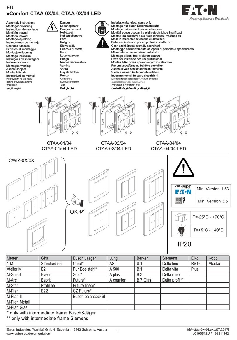
Eaton CTSA-0./04 Manual

Eaton

Eaton CTSA-0./04 Manual

Eaton P5-125/Z Manual

Eaton

Eaton P5-125/Z Manual

Eaton T6-160-6/V/SVB/HI11 Manual

Eaton

Eaton T6-160-6/V/SVB/HI11 Manual

Eaton COOPER POWER LS4R Series User manual

Eaton

Eaton COOPER POWER LS4R Series User manual

Eaton AT0 I Series Manual

Eaton

Eaton AT0 I Series Manual

Eaton LZMB Series Manual

Eaton

Eaton LZMB Series Manual

Eaton NR User manual

Eaton

Eaton NR User manual

Eaton ATC-100 Installation and operation manual

Eaton

Eaton ATC-100 Installation and operation manual

Eaton XNH00-1-S160 Manual

Eaton

Eaton XNH00-1-S160 Manual

Eaton Greengate NeoSwitch ONW-D-1001-MV-W User manual

Eaton

Eaton Greengate NeoSwitch ONW-D-1001-MV-W User manual

Eaton P1-25-I2H-SW Manual

Eaton

Eaton P1-25-I2H-SW Manual

Eaton P3 V/SVB Series Manual

Eaton

Eaton P3 V/SVB Series Manual

Eaton K1D Manual

Eaton

Eaton K1D Manual

Eaton Moeller IZM Series User manual

Eaton

Eaton Moeller IZM Series User manual

Eaton Cutler-Hammer J-Frame Series Guide

Eaton

Eaton Cutler-Hammer J-Frame Series Guide

Eaton SVB-PKZ0-CI Manual

Eaton

Eaton SVB-PKZ0-CI Manual

Eaton TM-1-8210 Series Manual

Eaton

Eaton TM-1-8210 Series Manual

Eaton Cutler-Hammer ATC-300 User manual

Eaton

Eaton Cutler-Hammer ATC-300 User manual

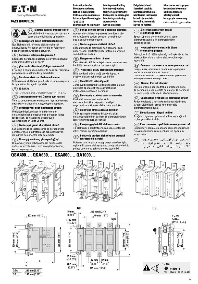
Eaton QSA400 Series Manual

Eaton

Eaton QSA400 Series Manual

Eaton DeviceNet E50DNA User manual

Eaton

Eaton DeviceNet E50DNA User manual

Eaton PV-25A-4P-AC-I2/SVB-SW/N Manual

Eaton

Eaton PV-25A-4P-AC-I2/SVB-SW/N Manual

Eaton XTCE095F F47 Series Manual

Eaton

Eaton XTCE095F F47 Series Manual

Eaton CEMU-01/03 Manual

Eaton

Eaton CEMU-01/03 Manual

Popular Switch manuals by other brands

SMC Networks SMC6224M Technical specifications

SMC Networks

SMC Networks SMC6224M Technical specifications

Aeotec ZWA003-S operating manual

Aeotec

Aeotec ZWA003-S operating manual

TRENDnet TK-209i Quick installation guide

TRENDnet

TRENDnet TK-209i Quick installation guide

Planet FGSW-2022VHP user manual

Planet

Planet FGSW-2022VHP user manual

Avocent AutoView 2000  AV2000BC AV2000BC Installer/user guide

Avocent

Avocent AutoView 2000 AV2000BC AV2000BC Installer/user guide

Moxa Technologies PT-7728 Series user manual

Moxa Technologies

Moxa Technologies PT-7728 Series user manual

Intos Electronic inLine 35392I operating instructions

Intos Electronic

Intos Electronic inLine 35392I operating instructions

Cisco Catalyst 3560-X-24T Technical specifications

Cisco

Cisco Catalyst 3560-X-24T Technical specifications

Asante IntraCore IC3648 Specifications

Asante

Asante IntraCore IC3648 Specifications

Siemens SIRIUS 3SE7310-1AE Series Original operating instructions

Siemens

Siemens SIRIUS 3SE7310-1AE Series Original operating instructions

Edge-Core DCS520 quick start guide

Edge-Core

Edge-Core DCS520 quick start guide

RGBLE S00203 user manual

RGBLE

RGBLE S00203 user manual

Thrustmaster FLIGHT SIMULATOR X quick guide

Thrustmaster

Thrustmaster FLIGHT SIMULATOR X quick guide

Southwire SURGE GUARD 41390 RVC troubleshooting guide

Southwire

Southwire SURGE GUARD 41390 RVC troubleshooting guide

Buhler Nivotemp NT 61 Brief instructions

Buhler

Buhler Nivotemp NT 61 Brief instructions

Kramer VS-41HDCP user manual

Kramer

Kramer VS-41HDCP user manual

Techly IDATA AU-270 user manual

Techly

Techly IDATA AU-270 user manual

Belkin F1U109 user manual

Belkin

Belkin F1U109 user manual

manuals.online logo
manuals.online logoBrands
  • About & Mission
  • Contact us
  • Privacy Policy
  • Terms and Conditions

Copyright 2025 Manuals.Online. All Rights Reserved.

6. Mounting instructions
(ASALMSN in deliver condition)
1) Switch off devices to be assembled
2) Assembling sequence as shown bellow
3) Operation check of NC-contact
Example:ASALMSN + MCB
7. Tripping- and contact-position-indicator:
Tripping indicator changes from white to blue in case of a electrically
tripping and vertical position (to the DIN-rail) of the yellow selector pin.
Horizontalpositionofselectorpincauseswhitetobluechangeinanycase
of tripping. Either at electrically or mechanically the "tripping indicator"
changestothe functionofa "Contact-position-indicator".Bythis factitis
possible to get information of the selector pin position when the NHK is
mounted already between other devices and selector cannot be seen.
8. Remark:
Subsequent mounting by the customer needs a operation test after
assembling.CorrectoperationisgivenifNC-contacts are closed incase
ofboth devicesare inOFF position.Function testfor electrically tripping
can be done without electric voltage as explained in item 5.
* Test must be done before electrification *
In case of incorrect working although mounting instruction has been
watched carefully, please return device to supplier. Don't start repair
yourself!Any warranty is lost in that case!
MOUNTING INSTRUCTION
Tripping Signal Switch ASALMSN
in acc. to IEC/EN 62019
1. Function:
ASALMSN is a retro-fit auxiliary switch.
The switch provides two signal/alarm functions, dependant upon the
position of the yellow selector pin. The yellow selector pin can be
turned between two positions thus selecting operation of the contacts
through, mechanical operation/electrical tripping or electrical tripping
only.
ASALMSN is delivered with the selector pin in the vertical position (to
the DIN-rail).
This is the “electrical tripping only” position as shown on the printed
picture on the device. It is possible to change operation of changeover-
contact 4.11-4.12/4.14 to “mechanical operation/electrical tripping” by a
900turn of the selector pin.
Operation of contact 1.11-1.12/1.14 is not changeable.
2. Additional feature: "low voltage contact operation".
Very low contact resistance can be reached by the help of selfcleaning
contacts. This is the reason why NHK is able to work under low voltage
conditions down to 5V DC minimum. When contacts are wired in series,
higher voltages are necessary.
3 contacts need 12 volts. 6 contacts in series need 24 V DC minimum
to work correctly. Small tolerances in operational voltages are possible
as samples given above 12 V (instead of 3 x 5 V) and 24 V (instead of
30 V DC).
3. Technical Data:
UMAX = 250VAC max. operational voltage
UMIN = 5V DC min. operational voltage
Ith = 4AAC rated thermal current
Util./cat. AC 12...2A 250 VAC
DC 12...0.5A 110 V DC
Max. permissible backup-fuse: 4AgL
4. Contacts and terminals:
4.11-4.12/4.14 changeover contact operation changeable.
1.11-1.12/1.14 changeover contact not changeable.
Terminal capacity 1x0,5mm² - 1 x 1,5mm², single wire or flexibly wire
Terminal capacity 2x0,5mm² - 2 x 1,5mm², single wire
Terminal capacity 1x2,5mm², flexibly wire,
Terminal screw torque 0,8-1Nm.
5. Operation test "electrically tripping"
Functionofchangeovercontact4.11-4.12/4.14canbetestedbytestpush
botton"T".Tripindicator willchangefromwhitetobluecolourinthiscase
as well as in case of a regular electric trip. Mechanically moving of the
switch from ON to OFF position will not change colour of trip indicator, if
yellow selector pin is in vertical position to the DIN rail.
GB 6. Montagehinweise
(ASALMSN-Auslieferungszustand)
1) Beide Geräte ausschalten
2) Montage gemäß nachstehender Bildfolge
3) Überprüfung des Ruhekontaktes
Beispiel:ASALMSN + LS
7. Auslöseanzeige/Schaltstellungsanzeige
In der Wahlstellung SEL= senkrecht zur DIN-Schiene, zeigt der Weiß-
Blau-Wechsel derAnzeige nur eine elektrische Auslösung an.
InderWahlstellungSEL= parallelzurDIN-Schiene,wirddieAuslösean-
zeigezueinerSchaltstellungsanzeige,ohneDifferenzierunghändische/
elektrischeAbschaltung.DadurchistauchimeingebautenZustanddurch
Handbetätigung des ASALMSN ein Rückschluss auf die nicht mehr
sichtbare Stellung von SEL möglich.
8. Hinweis
DernachträglicheAnbau durch denAnwender verlangt zur Vermeidung
von Funktionsstörungen eine Montagekontrolle. Richtige Montage liegt
nur dann vor, wenn der Ruhekontakt bei ausgeschaltetem, angekop-
pelten Schalter geschlossen ist. SEL = senkrecht zur DIN-Schiene. Die
elektrischeAuslösung ist gemäß Pkt. 5 zu kontrollieren.
* ACHTUNG: VOR INBETRIEBNAHME PRÜFEN!*
WirdtrotzBeachtungderMontagehinweisekeineeinwandfreieFunktion
desGeräteserreicht,kanndiesesschadhaftseinundistandenHersteller
einzusenden. Eigene Eingriffe sind nicht zulässig!
MONTAGEANLEITUNG
Auslösesignalschalter ASALMSN
IEC/EN 62019
1. Beschreibung:
DerASLMSN ist ein, nachträglich an Schalter anbaubarer Hilfsschalter,
der zwischen einer elektrischenAuslösung und einer Hand-Abschal-
tung des angekoppelten Gerätes unterscheiden kann. Es ist somit, je
nachAusschaltursache, eine unterschiedliche Signalisierung/Alarmie-
rung möglich.
ASALMSN wird mit dem Selektionsknopf in senkrechter Stellung (zur
DIN-Schiene)geliefert.Diesistdie“electricaltrippingonly”(nurelektrische
Auslösung) Position, wie auf dem seitlich am Gerät abgedruckten Bild
dargestellt.DerWechslerkontakt4.11-4.12/4.14kanndurcheine90Grad
DrehungdesSelektionsknopfes“mechanicaloperation/electricaltripping”
(Mechanische Betätigung/ElektrischeAuslösung) umgestellt werden.
Die Funktion des zweiten Kontaktes ist nicht wählbar. Dieser wird daher
immer händisch oder elektrisch aktiviert.
2. Zusatzfunktion-Kleinspannung:
Durch Kontakt-Relativbewegung zwischen Festkontakt und be-
weglichem Kontakt tritt bei jeder Schaltung eine ”Reinigung” der
Kontaktoberfläche ein. Damit wird erreicht, dass der Hilfsschalter
ASALMSN auch ein gutes Kleinsignal-Verhalten hat. Die Mindest-Be-
triebsspannung beträgt 5V = je Schaltstrecke. Bei Reihenschaltungen
ist das jeweils Vielfache der Mindest-Betriebsspannung vorzusehen,
zB. bei Serienschaltung von 3 xASALMSN mindestens 12V DC, bei 6
xASALMSN mindestens 24V DC. Geringfügige Unterschreitungen auf
den nächsten Nennwert sind zulässig.
3. Technische Daten:
UMAX = 250V ~ max. Betriebsspannung
UMIN = 5V = Mindest-Betriebsspannung je Schaltstrecke
Ith = 4A~ thermischer Dauerstrom
AC 12-Einsatz 2A bei 250V ~
DC 12-Einsatz 0,5A bei 110V
Max. Vorsicherung: 4AgL
4. Kontakte/Klemmen:
4.11-4.12/4.14 Wechsler, umschaltbar
1.11-1.12/1.14 Wechsler nicht umschaltbar
Klemmenquerschnitt 1x0,5mm² - 1 x 1,5mm², starr oder flexibler Leiter
Klemmenquerschnitt 2x0,5mm² - 2 x 1,5mm², starrer Leiter
Klemmenquerschnitt 1x2,5mm², flexibler Leiter
Drehmoment 0,8-1Nm.
5. Funktionsprüfung ”elektrische Auslösung”
Die Kontaktfunktion des Wechslers kann durch Betätigung der Kontroll-
taste ”T” überprüft werden. In diesem Fall, aber auch bei einer ”echten”
elektrischenAuslösungwechseltdieFarbederAuslöseanzeigevonweiß
auf blau. Eine händische Abschaltung verändert die Auslöseanzeige in
"SEL-Position ist senkrecht zur DIN-Schiene" nicht.
D
Eaton Industries (Austria) GmbH, Eugenia 1, 3943 Schrems, Austria
© 2020 by Eaton Industries (Austria) GmbH, www.eaton.eu/documentation
MA-eaton-ASALMSN.indd / 06.2020f / IL019190ZU / 150501428 / All Rights Reserved
www.eaton.com/recycling
(Estado de suministroASALMSN)
1) Desconectar aparatos
2) Montaje según la siguiente imagen
3) Verificación del contacto de reposo
Ejemplo:ASALMSN + MCB
7. Señalización de disparo/indicador de posición de
maniobra
En la posición SEL = vertical a barra DIN, el cambio de blanco a azul
de la indicación señaliza sólo un disparo eléctrico.
En la posición SEL = en paralelo a barra DIN, la señalización de
disparo se convierte en una indicación de posición de maniobra,
sin diferenciación entre desconexión manual/eléctrica. También es
posible, estando montada, una deducción de la posición ya invisible
de SEL con sólo pulsar manualmente elASALMSN.
8. Nota:
El montaje por parte del usuario requiere un control de montaje
para evitar averías en el funcionamiento. Sólo se considerará que el
montaje es correcto cuando el contacto de reposo esté cerrado con
el Contacto desconectado y acoplado. SEL = vertical a barra DIN. El
disparo eléctrico debe controlarse según el punto 5.
* ATENCIÓN: ¡CONTROLAR ANTES
DE LA PUESTA EN SERVICIO!*
Si a pesar de tener en cuenta las instrucciones de montaje, no se con-
sigue un funcionamiento correcto del dispositivo, es posible que éste
sea defectuoso y deberá devolverse al fabricante. ¡No está permitido
manipular el dispositivo!
INSTRUCCIONES DE MONTAJE
Contacto de señalización de disparo ASALMSN
IEC/EN 62019
1. Descripción:
ElASALMSN es un Contacto auxiliar acoplable posteriormente que
puede distinguir entre un disparo eléctrico y una desconexión manual
del aparato acoplado.Así pues, de este modo es posible obtener una
señalización/alarma diferente según la causa de la desconexión.
ASALMSN se suministra con el pasador selector en posición vertical
(en el carril DIN). Esta es la posición de "sólo disparo eléctrico" como
se muestra en la imagen impresa en el dispositivo. Es posible cambiar
la operación de conmutador-contacto 4.11-4.12 / 4.14 a "funcionamien-
to mecánico/disparo eléctrico" por un giro de 900 del pasador selector.
La función del segundo contacto no es seleccionable. Por este motivo
siempre se activará de forma manual o eléctrica.
2. Función adicional: “Operación a baja tensión :
Mediante un movimiento relativo de contactos entre el contacto fijo y
el contacto móvil, en cada conexión se produce una “limpieza” de la
superficie del contacto. Con ello se consigue que el Contacto auxiliar
ASALMSN también cuente con un buen comportamiento de señal
pequeña. La tensión asignada mínima es de 5V DC por cada tramo
de conexión. En circuitos en línea debe preverse la multiplicación
correspondiente por la tensión asignada mínima, p. ej. , en circuito en
serie de 3 xASALMSN un mínimo de 12 V DC, en 6 xASALMSN un
mínimo de 24 V DC.
Se permite que el siguiente valor nominal se sobrepase ligeramente
por debajo.
3. Características técnicas:
UMAX = 250VAC máx.
UMIN = 5V DC
Ith = 4AAc
12AC 2Aa 250 V
DC 12 0.5Aa 110 V
Fusible previo máx.: 4AgL
4. Contactos/bornes:
4.11-4.12/4.14 Selector, conmutable
1.11-1.12/1.14 Selector no conmutable
Sección de bornes 1x0,5mm² - 1 x 1,5mm², cable rígido o (cable)
flexible
Sección de bornes 2x0,5mm² - 2 x 1,5mm², cable rígido
Sección de bornes 1x2,5mm², cable flexible
Par de apriete 0.8-1 Nm.
5. Control de funcionamiento “disparo eléctrico”
La función de contacto del conmutador puede controlarse accionando
la tecla de control “T”. En este caso, pero también en caso de un
disparo eléctrico “real”, el color de la señalización de disparo cambia
de blanco a azul. Una desconexión manual no modifica la señalización
de disparo en «posición SEL vertical a barra DIN».
6. Instrucciones de montaje
E