manuals.online logo
Brands
  1. Home
  2. •
  3. Brands
  4. •
  5. Eaton
  6. •
  7. Switch
  8. •
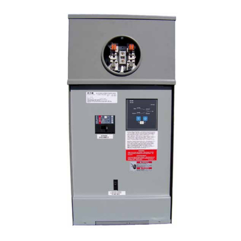
  9. Eaton CH10GEN5030SN User manual

Eaton CH10GEN5030SN User manual

This manual suits for next models

3

Other Eaton Switch manuals

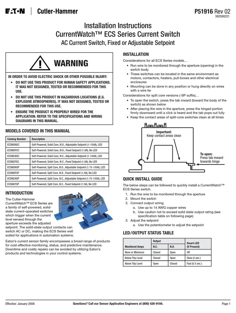
Eaton P1 /E Manual

Eaton

Eaton P1 /E Manual

Eaton T3 I2H/RT Series Manual

Eaton

Eaton T3 I2H/RT Series Manual

Eaton P5-125/Z Manual

Eaton

Eaton P5-125/Z Manual

Eaton GHG 273 User manual

Eaton

Eaton GHG 273 User manual

Eaton TM-1-8210 Series Manual

Eaton

Eaton TM-1-8210 Series Manual

Eaton RMQ-Titan M22 Series Manual

Eaton

Eaton RMQ-Titan M22 Series Manual

Eaton ATC-100 Manual

Eaton

Eaton ATC-100 Manual

Eaton Cooper Power System LCR 6600 RFN Manual

Eaton

Eaton Cooper Power System LCR 6600 RFN Manual

Eaton Greengate NeoSwitch ONW-D-1001-MV-W User manual

Eaton

Eaton Greengate NeoSwitch ONW-D-1001-MV-W User manual

Eaton Power Xpert PXES4P Series User manual

Eaton

Eaton Power Xpert PXES4P Series User manual

Eaton AT0 I Series Manual

Eaton

Eaton AT0 I Series Manual

Eaton QSA400 Series Manual

Eaton

Eaton QSA400 Series Manual

Eaton NR User manual

Eaton

Eaton NR User manual

Eaton CurrentWatch ECS7 Series User manual

Eaton

Eaton CurrentWatch ECS7 Series User manual

Eaton DMV160N Manual

Eaton

Eaton DMV160N Manual

Eaton Edison Cooper Power Series User manual

Eaton

Eaton Edison Cooper Power Series User manual

Eaton BZM-XTVD Manual

Eaton

Eaton BZM-XTVD Manual

Eaton Cutler-Hammer ATC-300 User manual

Eaton

Eaton Cutler-Hammer ATC-300 User manual

Eaton COOPER POWER SERIES User manual

Eaton

Eaton COOPER POWER SERIES User manual

Eaton XNH1-1-A Series Manual

Eaton

Eaton XNH1-1-A Series Manual

Eaton LSA-PKZ0-E Manual

Eaton

Eaton LSA-PKZ0-E Manual

Eaton DILMP Series Manual

Eaton

Eaton DILMP Series Manual

Eaton P5-125/E Manual

Eaton

Eaton P5-125/E Manual

Eaton TRIPP LITE U360-004-IND User manual

Eaton

Eaton TRIPP LITE U360-004-IND User manual

Popular Switch manuals by other brands

SMC Networks SMC6224M Technical specifications

SMC Networks

SMC Networks SMC6224M Technical specifications

Aeotec ZWA003-S operating manual

Aeotec

Aeotec ZWA003-S operating manual

TRENDnet TK-209i Quick installation guide

TRENDnet

TRENDnet TK-209i Quick installation guide

Planet FGSW-2022VHP user manual

Planet

Planet FGSW-2022VHP user manual

Avocent AutoView 2000  AV2000BC AV2000BC Installer/user guide

Avocent

Avocent AutoView 2000 AV2000BC AV2000BC Installer/user guide

Moxa Technologies PT-7728 Series user manual

Moxa Technologies

Moxa Technologies PT-7728 Series user manual

Intos Electronic inLine 35392I operating instructions

Intos Electronic

Intos Electronic inLine 35392I operating instructions

Cisco Catalyst 3560-X-24T Technical specifications

Cisco

Cisco Catalyst 3560-X-24T Technical specifications

Asante IntraCore IC3648 Specifications

Asante

Asante IntraCore IC3648 Specifications

Siemens SIRIUS 3SE7310-1AE Series Original operating instructions

Siemens

Siemens SIRIUS 3SE7310-1AE Series Original operating instructions

Edge-Core DCS520 quick start guide

Edge-Core

Edge-Core DCS520 quick start guide

RGBLE S00203 user manual

RGBLE

RGBLE S00203 user manual

Thrustmaster FLIGHT SIMULATOR X quick guide

Thrustmaster

Thrustmaster FLIGHT SIMULATOR X quick guide

Southwire SURGE GUARD 41390 RVC troubleshooting guide

Southwire

Southwire SURGE GUARD 41390 RVC troubleshooting guide

Buhler Nivotemp NT 61 Brief instructions

Buhler

Buhler Nivotemp NT 61 Brief instructions

Kramer VS-41HDCP user manual

Kramer

Kramer VS-41HDCP user manual

Techly IDATA AU-270 user manual

Techly

Techly IDATA AU-270 user manual

Belkin F1U109 user manual

Belkin

Belkin F1U109 user manual

manuals.online logo
manuals.online logoBrands
  • About & Mission
  • Contact us
  • Privacy Policy
  • Terms and Conditions

Copyright 2025 Manuals.Online. All Rights Reserved.

Effective January 2009
Supplement to IB 70-8447
CH10GEN5030SN
CH10GEN5030RSN
CH10GEN5050SN
CH10GEN5050RSN
Instruction Booklet IB 70-8704
Eaton Corporation’s Family of Manual Transfer Switches
for Residential and Light Commercial Applications
Instruction and Operation
Manual for Eaton
Emergency Generator
Panel Model Numbers:
• CH10GEN5030SN
• CH10GEN5030RSN
• CH10GEN5050SN
• CH10GEN5050RSN
Introduction
The Eaton 10 Circuit Manual Transfer Switch is
intended to be used with Eaton generators but
may be used with any generators. These Manual
Transfer Switches are rated for 50 amp utility input
and 30 amp or 50 amp generator input respec-
tively at 240 Vac. These devices come equipped
to power nine emergency circuits. There are eight
single-pole emergency circuit breakers and one
2- pole emergency circuit breaker included.
These devices are intended for use with genera-
tors that are wired as either Separately Derived
systems (neutral and ground bonded together
at the generator – typically protected by a GFCI,
ground fault circuit interrupter, on the generator)
or Non-Separately Derived systems (neutral and
ground are NOT bonded at the generator). Refer
to the NFPA 70, National Electrical Code, for
proper connection and further definition.
Contact the generator manufacturer if you
are unsure how the generator is configured
(Separately Derived or Non-Separately Derived). It
is extremely important that you know this informa-
tion prior to connecting the generator to this or
any other transfer switch.
2
Instruction Booklet IB 70-8704
Effective January 2009
Eaton Corporation’s Family of ManualTransfer Switches
for Residential and Light Commercial Applications
EATON CORPORATION www.eaton.com
Figure 1. Manual Transfer Switch with Door Open.
These Manual Transfer Switches utilize 3-pole switching devices to
determine which power source, utility or generator, are powering
the nine emergency circuits. The 3-pole switching devices are inter-
locked via a manual slide type interlock. The intent of the interlock is
to ensure that only ONE source is powering the emergency circuits
and to prevent back feeding of the utility with the generator or inad-
vertent paralleling of the utility and generator sources.
Figure 2. Connection Locations for a Separately Derived System.
Connection for a Separately Derived System:
1. For generators that are configured as a Separately Derived
system. These units typically contain GFCI protection on the
generator.
a. Connect the two hot wires from the utility to the utility
breaker poles #1 and #2. Connect the utility neutral to the
utility breaker pole #3. See Figure 2 for clarification.
b. Connect the two hot wires from the generator to the
generator breaker poles #1 and #2. Connect the generator
neutral to the generator breaker pole #3. See Figure 2 for
clarification.
CAUTION
FOr A sepArATely derIved sysTem FAIlUre TO CONNeCT As
desCrIbed IN These INsTrUCTIONs wIll resUlT IN NUIsANCe TrIp-
pINg OF The geNerATOr gFCI CIrCUIT breAker.
Slide Interlock
(To operate, turn
the utility breaker
to the OFF
position. Lift the
interlock and hold.
Turn the generator
breaker to the ON
position. Release
the interlock.
Reverse these
steps to power
loads via utility).
Utility Breaker Shown
in the ON Position
Generator Breaker
Shown in the OFF
Position
Utility Pole #2
Utility Pole #1
Utility Pole #3
Generator Pole #1
Generator Pole #2
Generator Pole #3
3
Instruction Booklet IB 70-8704
Effective January 2009
Eaton Corporation’s Family of ManualTransfer Switches
for Residential and Light Commercial Applications
EATON CORPORATION www.eaton.com
Figure 3. Connection Locations for a Separately Derived System.
Connection for a Non-Separately Derived System:
2. For portable generators that are configured as a
Non- Separately Derived system.
a. Connect the two hot wires from the utility to the utility
breaker poles #1 and #2. Connect the utility neutral to the
utility neutral lug. See Figure 3 for clarification.
b. Connect the two hot wires from the generator to the gen-
erator breaker poles #1 and #2. Connect the generator
neutral to the neutral bar. See Figure 3 for clarification.
dANger
FOr A NON-sepArATely derIved sysTem dO NOT CONNeCT The
UTIlITy Or geNerATOr NeUTrAls TO The UTIlITy breAker Or
geNerATOr breAker NeUTrAl pOle. These NeUTrAls mUsT be TIed
TOgeTher AT The NeUTrAl bAr. FAIlUre TO dO sO wIll leAd TO
eqUIpmeNT FAIlUre, FIre, Or pOssIble deATh dUe TO A FlOATINg
NeUTrAl CONdITION.
Do Not Connect
the Utility or
Generator
Neutrals to the
Breaker if the
Generator is
Configured as a
Non-Separately
Derived System.
Leave These
Poles Empty.
Utility Pole #1
Utility Neutral
Utility Pole #2
Generator Neutral
Generator Pole #1
Generator Pole #2
Instruction Booklet IB 70-8704
Effective January 2009
Eaton Corporation’s Family of ManualTransfer Switches
for Residential and Light Commercial Applications
Eaton Corporation
Electrical Group
1000 Cherrington Parkway
Moon Township, PA 15108
United States
877-ETN-CARE (877-386-2273)
Eaton.com
© 2009 Eaton Corporation
All Rights Reserved
Printed in USA
Publication No. IB 70-8704 / TBG228
January 2009
PowerChain Management is a registered
trademark of Eaton Corporation.
All other trademarks are property of their
respective owners.
The instructions for installation, testing, maintenance, or repair
herein are provided for the use of the product in general commercial
applications and may not be appropriate for use in nuclear applica-
tions. Additional instructions may be available upon specific request
to replace, amend, or supplement these instructions to qualify them
for use with the product in safety-related applications in a nuclear
facility.
The information, recommendations, descriptions, and safety nota-
tions in this document are based on Eaton’s experience and judg-
ment with respect to Retrofitting of Power Breakers. This instruction-
al literature is published solely for information purposes and should
not be considered all-inclusive. If further information is required, you
should consult an authorized Eaton sales representative.
The sale of the product shown in this literature is subject to the
terms and conditions outlined in appropriate Eaton selling policies
or other contractual agreement between the parties. This literature
is not intended to and does not enlarge or add to any such contract.
The sole source governing the rights and remedies of any purchaser
of this equipment is the contract between the purchaser and Eaton.
NO WARRANTIES, EXPRESSED OR IMPLIED, INCLUDING
WARRANTIES OF FITNESS FOR A PARTICULAR PURPOSE OR
MERCHANTABILITY, OR WARRANTIES ARISING FROM COURSE
OF DEALING OR USAGE OF TRADE, ARE MADE REGARDING
THE INFORMATION, RECOMMENDATIONS, AND DESCRIPTIONS
CONTAINED HEREIN. In no event will Eaton be responsible to the
purchaser or user in contract, in tort (including negligence), strict
liability or otherwise for any special, indirect, incidental or conse-
quential damage or loss whatsoever, including but not limited to
damage or loss of use of equipment, plant or power system, cost
of capital, loss of power, additional expenses in the use of existing
power facilities, or claims against the purchaser or user by its cus-
tomers resulting from the use of the information, recommendations
and description contained herein.