OfiTE 150-50 User manual
Differential Sticking Tester
Part No. 150-50
Instruction Manual
Updated 5/29/2009
Ver. 2.0
OFI Testing Equipment, Inc.
11302 Steeplecrest Dr. · Houston, Texas · 77065 · U.S.A.
Tele: 832.320.7300 · Fax: 713.880.9886 · www.ofite.com
©Copyright OFITE 2011

Table of
Contents
Intro.......................................................................................................2
Description ...........................................................................................2
Components.........................................................................................3
Safety ...................................................................................................5
Test Procedure ..................................................................................6
Timed Filtration ................................................................................6
Fixed Cake Thickness....................................................................11
Disassembly.......................................................................................12
Theory.................................................................................................13
Example .........................................................................................15
Worksheet ......................................................................................16
Maintenance.......................................................................................17
Diagrams ...........................................................................................18
Full Unit ..........................................................................................18
Cell Assembly ................................................................................19
OFITE, 11302 Steeplecrest Dr., Houston, TX 77065 USA / Tel: 832-320-7300 / Fax: 713-880-9886 / www.ofite.com 1

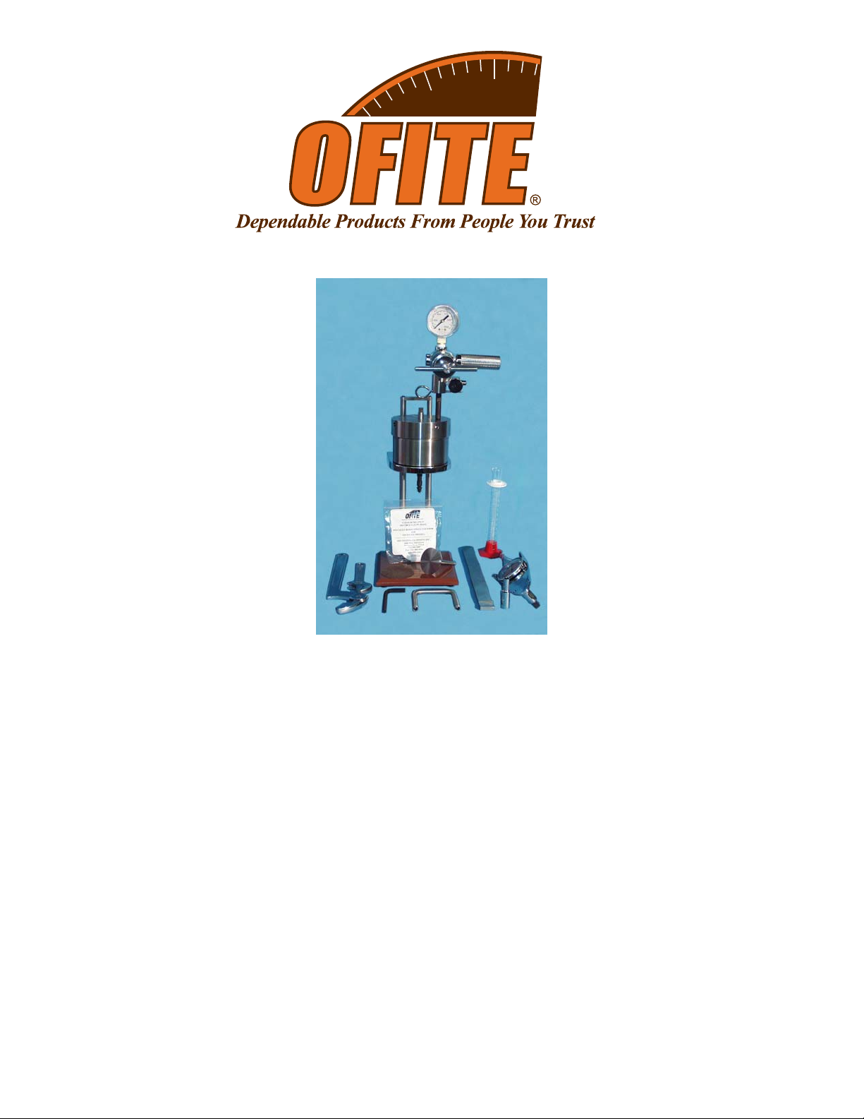
The OFITE Differential Sticking Tester measures the “Stuck Pipe Tendency
Coefficient” of drilling fluids, and also determines how effective lubricants or
treatments might be with any given drilling fluid. This coefficient takes into
account both the friction, or “stickiness”, of the filter cake, as well as the
amount of cake building that must occur in order to freeze or stick the pipe
in the hole. The coefficient is determined by running a Timed Filtration test.
By measuring the area of cake building during a test, the “Bulk Sticking
Coefficient” is obtained and read directly at the conclusion of the test. How
likely a given fluid will be to produce a stuck pipe situation and how effec-
tive a given treatment may be, can be immediately determined on-site.
The unit is normally pressurized by a CO2pressuring assembly, but any
nitrogen source will also work. If nitrogen is used, the tester apparatus
must be fitted with a suitable nitrogen regulator, gauges, valves, and high-
pressure hoses. The standard test uses 477.5 PSI (3,291 kPa) applied to
a 200-mL stainless steel vessel. The unit includes both a flat-faced plate
and a plate of 12½" (31.75 cm) spherical radius, which simulates the pipe
inside the casing or collars in the borehole. For samples that adhere more
to the plate than to the filter paper, stainless steel micro-corrugation disks
are provided. For convenience a stainless steel carrying case is available
as an optional item.
OFITE, 11302 Steeplecrest Dr., Houston, TX 77065 USA / Tel: 832-320-7300 / Fax: 713-880-9886 / www.ofite.com 2
Description
Intro

Components #130-10-52 Jam Nut, 3/8-24, Qty: 2
#142-56 O-ring
#150-52 Neoprene Gasket
#150-53 Plastic Gasket
#150-54 Torque Wrench
#150-55 Spanner Wrench
#150-56 Test Cell O-ring
#150-57 5⁄16" Socket with 3⁄8" Drive
#150-58 Torque Plate; Flat Bottom
#150-59 Torque Plate; Spherical
#153-16 Glass Graduated Cylinder; 25 mL × 2⁄10 mL
#170-04 CO2Pressurization Unit:
#143-02-10 CO2Puncture Head Assembly
#143-03 Barrel for CO2Cartridge
#170-08 Regulator
#170-20 Manifold Block
#170-32 1⁄8" × 1⁄8" NPT Male Needle Valve
#171-22 Retainer Pin
#171-34 1500-PSI Gauge; 2"; ¼" NPT Bottom
#170-13 Test Cell O-ring; Buna N
#170-15 Base
#170-16 Valve Stem; Qty: 2
#170-17 Valve Stem O-ring; Qty: 10
#170-19 2½" (6.35 cm) Filter Paper; Specially Hardened for Filter
Presses
#170-35 6" Adjustable Wrench
#170-44 ½" Rubber Foot; Qty: 4
#171-79 ¼" Hex Wrench
OFITE, 11302 Steeplecrest Dr., Houston, TX 77065 USA / Tel: 832-320-7300 / Fax: 713-880-9886 / www.ofite.com 3

Optional:
Yoke for Fixed Cake Thickness Test - Special Order Only
#150-50-SP Spare Parts for #150-50:
#142-56 O-ring; Qty: 12
#143-02-13 O-ring for Puncture Pin Holder Assembly; CO2Cartridge;
Qty: 6
#143-02-14 O-ring for Puncture Pin Holder Assembly; Qty: 4
#143-05 EZ Puncture CO2Bulbs; 8-Gram; UN #1013; Package of
10; Qty: 30
#143-06 Safety Bleeder Valve
#143-07 Regulator Repair Kit for #143-00
#143-22 Gasket for Puncturing Pin; Qty: 12
#150-51 Locking Mesh Disc; Qty: 10
#150-52 Neoprene Gasket; Qty: 10
#150-53 Plastic Gasket; Qty: 8
#153-16 Glass Graduated Cylinder; 25 mL × 2/10 mL; Qty: 2
#170-13 Test Cell O-ring; Buna N; Qty: 4
#170-16 Valve Stem; Qty: 2
#170-17 Valve Stem O-ring; Qty: 20
#170-19 2½" (6.35 cm) Filter Paper; Specially Hardened for Filter
Presses; Qty: 5
#170-23 60-Mesh Screen; Qty: 8
#171-22 Retainer Pin; Qty: 2
#171-79 ¼" Hex Wrench
OFITE, 11302 Steeplecrest Dr., Houston, TX 77065 USA / Tel: 832-320-7300 / Fax: 713-880-9886 / www.ofite.com 4

Safety Nitrogen must be supplied in an approved Nitrogen Gas Cylinder and
secured to meet safety standards. Do not use nitrous oxide cartridges as
pressure sources.
Due to the high pressures involved in this test, extreme care must be exer-
cised at all times. All safety precautions must be met, especially in the cell
breakdown procedure after the filtration procedure has been completed.
Never transport CO2bulbs or cartridges by airplane without proper packag-
ing. Cabin depressurization could cause them to explode.
Before pressuring, always check to be sure the regulator is in a closed
position by ensuring the T-screw is backed out and free turning. Insert and
puncture the CO2cartridge by turning the barrel only a quarter turn past the
actual puncture point. Adjust the regulator to the desired pressure with the
regulator T-screw. With the Differential Sticking Tester, never exceed 500
PSI (3,450 kPa). When de-pressurizing, shut off the pressure supply, then
bleed off the system of pressure with the valve, and finally back out the
regulator T-screw.
OFITE, 11302 Steeplecrest Dr., Houston, TX 77065 USA / Tel: 832-320-7300 / Fax: 713-880-9886 / www.ofite.com 5
Test
Procedure
Timed Filtration
The Differential Sticking Tester is capable of performing two different tests.
Both of these tests determine the Stuck Tendency Coefficient and the Bulk
Sticking Coefficient. The Timed Filtration test uses a pre-determined stick-
ing time. The Fixed Cake Thickness test uses an optional yoke assembly
to determine the amount of time required to create a cake of specified
thickness. The general procedure for assembling and operating the instru-
ment is basically the same for either test.
Two torque plates are provided with the unit. The spherical torque plate
(#150-59) has a very slight curve on the bottom. The radius of the curve is
12.5" (31.75 cm) and simulates a 25" (63.5 cm) diameter drill casing or col-
lar. The flat torque plate (#150-58) is completely flat across the surface.
The difference between the two is sometimes difficult to see. To distinguish
between the two, place them next to each other on a flat surface. The
spherical torque plate will rock slightly, while the flat torque plate will sit
firmly.
1. Make sure the unit is clean and dry before beginning a test.
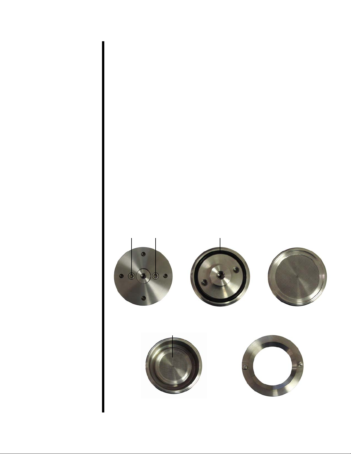
2. Open the test cell. Remove the inner cap by turning the cell over and
removing the two allen screws with the supplied wrench.
3. Inspect the o-ring on the bottom of the inner cap. Replace it if it shows
signs of wear or damage.
OFITE, 11302 Steeplecrest Dr., Houston, TX 77065 USA / Tel: 832-320-7300 / Fax: 713-880-9886 / www.ofite.com 6
Cell Bottom
Cell - Inside Retaining Ring
Inner Cap - Bottom Inner Cap - Top
Allen Screws O-ring
Inner Cap

4. Place a sheet of filter paper on top of the screen on the inner cap. On
top of the filter paper, place the rubber gasket, then the plastic ring.
The locking mesh disk can be used to lock the filter cake to the paper
so that it does not stick to the torque plate face and break lose from the
filter paper. If you choose to use the locking mesh disk, place it on top
of the filter paper, beneath the rubber gasket.
5. Screw the retaining ring in place on top of the filter paper and gaskets.
Be sure to keep the gaskets centered.
6. Place the inner cap back into the cell. Make sure the o-ring seats prop-
erly beneath the inner cap. Refer to the photos on page 8.
7. Turn the cell over and secure the inner cap with the two allen screws.
8. Tighten the retaining ring securely with the supplied retainer wrench.
9. Inspect the o-rings on the valve stems and replace any that show signs
of wear or damage. Screw one of the valve stems into the hole in the
base of the test cell and hand tighten.
OFITE, 11302 Steeplecrest Dr., Houston, TX 77065 USA / Tel: 832-320-7300 / Fax: 713-880-9886 / www.ofite.com 7
Tip
Retainer Wrench (#150-55)
Retaining Ring
Plastic Gasket (#150-53)
Neoprene Gasket (#150-52)
Locking Mesh Disk (#150-51)
Filter Paper (#170-19)
Inner Cap with Screen
(#150-50-5)
10. Place the cell on the stand. Make sure the four holes in the base of the
cell line up with the stand tips.
11. Fill the cell with sample fluid to the scribed line.
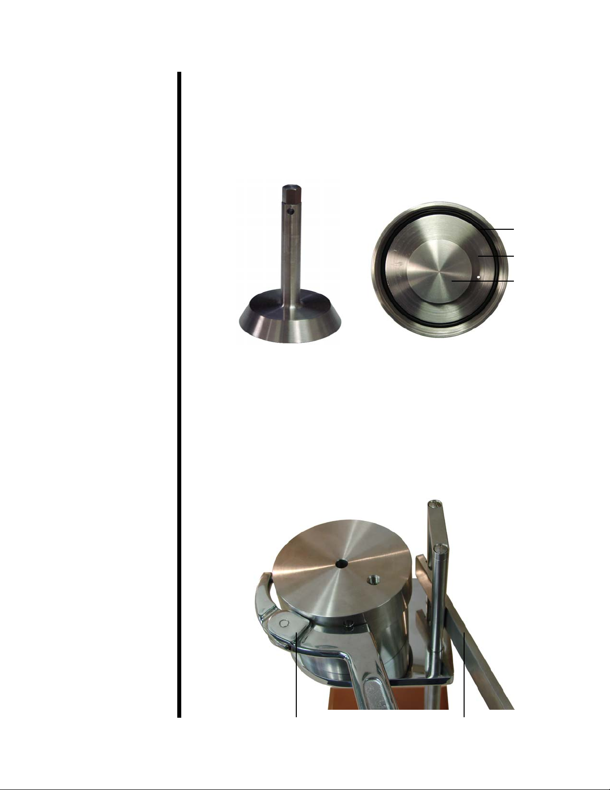
12. Insert the stem of the torque plate through the hole in the cell cap as far
as possible. The face of the plate should be facing towards the inside
of the cell. Be careful not to cut the o-ring.
13. Screw the cell cap onto the test cell body. Make sure the o-ring is
properly seated in the groove in the cell cap.
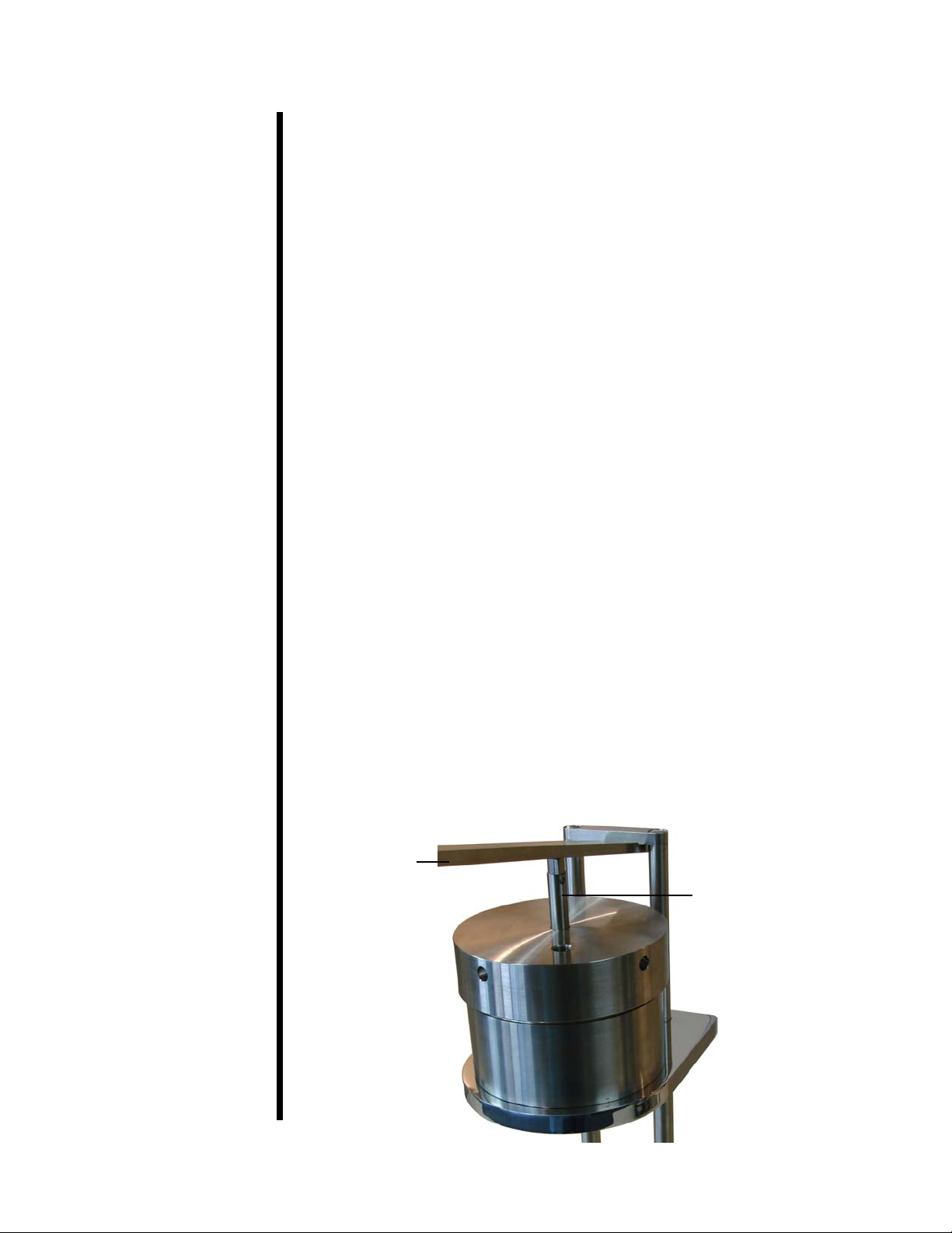
14. Tighten the cell cap using the supplied spanner wrench. For additional
leverage, place the lever arm horizontally between the two support legs.
Once the cell cap is tightened, rotate the cell on the stand until the
valve stem hole is oriented away from the stand supports. This will pro-
vide more space for the torque lever.
OFITE, 11302 Steeplecrest Dr., Houston, TX 77065 USA / Tel: 832-320-7300 / Fax: 713-880-9886 / www.ofite.com 8
Tip
Spanner Wrench Lever Arm
Cell Cap
Torque Plate
O-ring
Torque Plate
Lever Arm
Torque Plate Stem
OFITE, 11302 Steeplecrest Dr., Houston, TX 77065 USA / Tel: 832-320-7300 / Fax: 713-880-9886 / www.ofite.com 9
15. Screw the other valve stem into the hole in the cell cap and hand tighten.
16. Place the CO2assembly onto the top valve stem and secure it in place
with the retaining pin.
17. Unscrew (counter-clockwise) the regulator T-screw until it turns freely.
18. Remove the barrel from the regulator. Place a CO2cartridge into the
barrel and tighten the barrel to the puncture head until the cartridge
punctures.
19. Tighten (clockwise) the regulator T-screw until the gauge reads 477.5
PSI (3,292 kPa).
20. Place the 25 mL graduated cylinder under the cell and open the lower
valve stem by turning it counter-clockwise ¼ turn.
21. Make sure the torque plate is up as far as possible by turning and
pulling it upward.
22. Open the top valve stem ¼ turn to initiate filtration. Record the time of
the start of the test.
23. Continue filtration for 10 minutes, or until the desired filtrate volume is
collected.
If the yoke option is being used, filter until the desired cake thickness is
reached (usually 2/32" / 1.6 mm). Refer to page 11 for details.
24. Align the groove in the lever under the column top cross support and
press the torque plate down into the cell. Continue to hold the torque
plate all the way down against the screen until the pressure equalizes
sufficiently to allow the plate to stick. This usually takes about two min-
utes and will require 50 to 80 pounds (23 to 36 kg) of force on the end
of the lever.
Other manuals for 150-50
1
Table of contents
Other OfiTE Test Equipment manuals


