manuals.online logo
Brands
  1. Home
  2. •
  3. Brands
  4. •
  5. EBS
  6. •
  7. Transmitter
  8. •
  9. EBS LX2NB Assembly instructions

EBS LX2NB Assembly instructions

LX2NB Manual v.1.3 Page 1 / 57
GPRS TRANSMITTER
LX2NB
Installation and
programming manual
Version o the manual: v1.3
Date o issue: 2015.02.23
Firmware version: LX2NB-2.0rc21
GPRS transmitter con igurator version: 1.3.39.012
LX2NB Manual v.1.3 Page 2 / 57
DECLARATION OF COMPLIANCE
We, EBS Sp. z o.o., declare with ull responsibility that the present
product meets all requirements provided or in the Directive
1999/5/EC o European Parliament and Council dated 9 March 1999
The copy o the “Declaration o Compliance” can be ound at
http://www.ebs.pl/en/certi icates/ .
IMPORTANT INFORMATION
Crossed symbol o a trash bin means that at the territory o European
Union, the product, a ter inishing its use ul li e, shall be disposed o
in a separate, specially dedicated collection point. It re ers to the
equipment itsel and its accessories marked with that symbol. The
products shall not be disposed o together with non-sortable
municipal waste.
The content o the document is presented “as is”. The present
document shall not be deemed to be providing any warranties, either express or
implicit, including but not limited to, any implied warranties o merchantability or
itness or a particular purpose, unless it is required by relevant law. The
manu acturer reserves the right to amend the present document or withdraw it any
time, without notice.
The manu acturer o the equipment promotes the sustainable development policy. It
reserves the right to modi y and improve any unctions o the product described in
the present document without previous notice.
The availability o particular unctionalities will depend on the so tware version o
the equipment. Details can be ound at the nearest dealer o the equipment.
In no event, the Manu acturer shall be held liable or any loss o data or loss o
pro its or any speci ic, incidental, consequential or indirect damages caused in any
way.
MANUFACTURER
EBS Sp. z o. o.
59 Bronislawa Czecha St.
04-555 Warsaw, POLAND
E-mail : [email protected]
Technical support: [email protected]
Webpage : www.ebs.pl
LX2NB Manual v.1.3 Page 3 / 57
TABLE OF CONTENTS
1.
INTRODUCTION............................................................................................... 6
2.
FUNCTIONAL AND TECHNICAL PARAMETERS ....................................................... 7
3.
ASSEMBLY AND WIRING................................................................................... 8
3.1.
LX2NB TRANSMITTER................................................................................ 8
3.2.
INPUT CONFIGURATION ............................................................................ 9
3.3.
REMOTE CONTROL CONFIGURATION (ONLY LX2NB-5R VERSION) ................ 10
3.4.
LX-ZAS POWER SUPPLY........................................................................... 10
4.
QUICK START PROCEDURE ............................................................................. 12
5.
OPERATION .................................................................................................. 13
6.
CONFIGURATION PROGRAM ............................................................................ 15
6.1.
INITIAL REMARKS .................................................................................. 15
6.2.
COMPUTER – REQUIREMENTS .................................................................. 15
6.3.
PROGRAM FUNCTIONS ............................................................................ 15
6.3.1.
File->New ....................................................................................... 16
6.3.2.
File->Open...................................................................................... 16
6.3.3.
File->Save ...................................................................................... 17
6.3.4.
File->Language ............................................................................... 17
6.3.5.
File->Connections ............................................................................ 17
6.3.5.1.
Local connection ....................................................................... 17
6.3.5.2.
Remote connection.................................................................... 18
6.3.6.
File->Automatic device settings backup .............................................. 19
6.3.7.
File->Exit........................................................................................ 19
6.3.8.
Operations->Read ........................................................................... 20
6.3.9.
Operations->Send ........................................................................... 20
6.3.10.
Operations->Restore de ault settings ................................................. 20
6.3.11.
Operations->System events history ................................................... 21
6.3.12.
Operations->Device monitor ............................................................. 21
6.3.13.
Help->About program ...................................................................... 21
7.
PROGRAMMABLE PARAMETERS........................................................................ 22
7.1.
ACCESS................................................................................................. 22
7.1.1.
Parameters ..................................................................................... 22
7.1.1.1.
Device mode ............................................................................ 22
7.1.1.2.
GPRS test time ......................................................................... 23
7.1.1.3.
SMS mode a ter unsuccess ul attempts ........................................ 23
7.1.1.4.
SMS test time ........................................................................... 23
7.1.1.5.
Server phone number ................................................................ 23
7.1.1.6.
Send events via SMS immediately ............................................... 23
7.1.2.
APN Parameters............................................................................... 23
7.1.2.1.
APN ......................................................................................... 23
7.1.2.2.
User ID .................................................................................... 23
7.1.2.3.
User password .......................................................................... 24
7.1.2.4.
DNS1 and DNS2........................................................................ 24
7.1.3.
Main Server Parameters.................................................................... 24
7.1.3.1.
Server IP Address ..................................................................... 24
7.1.3.2.
Server port............................................................................... 24
7.1.3.3.
Interval between subsequent connection attempts ........................ 24
7.1.3.4.
Number o connection attempts .................................................. 24
7.1.3.5.
Order o connection to servers .................................................... 24
7.1.4.
Backup server parameters ................................................................ 25
7.1.4.1.
IP server address ...................................................................... 25
7.1.4.2.
Server port............................................................................... 25
7.1.4.3.
Interval between subsequent connection...................................... 25
7.1.4.4.
Number o connection attempts .................................................. 25
7.1.4.5.
Disconnect a ter time limit.......................................................... 25
7.1.5.
Access ............................................................................................ 25
7.1.5.1.
Service code............................................................................. 25
7.1.5.2.
Restricted user’s service code ..................................................... 26
LX2NB Manual v.1.3 Page 4 / 57
7.1.5.3.
PIN o SIM card......................................................................... 26
7.2.
TRANSMISSION...................................................................................... 26
7.3.
INPUTS/OUTPUTS ................................................................................... 26
7.3.1.
Inputs con iguration ......................................................................... 27
7.3.1.1.
NO/NC/EOL-NO/EOL-NC/DEOL-NO/DEOL-NC ................................ 27
7.3.1.2.
Delay [ms] ............................................................................... 27
7.3.1.3.
Lock ........................................................................................ 27
7.3.2.
Partitions ........................................................................................ 29
7.3.2.1.
Partition arming input ................................................................ 29
7.3.2.2.
Inputs assigned to partitions ...................................................... 29
7.3.2.3.
Delayed inputs.......................................................................... 30
7.3.2.4.
Exit time .................................................................................. 30
7.3.2.5.
Entry time ................................................................................ 30
7.3.3.
Output con iguration ........................................................................ 30
7.3.3.1.
Activation mode and timing ........................................................ 30
7.3.3.2.
Conditions ................................................................................ 31
7.3.3.3.
Additional conditions.................................................................. 31
7.3.4.
Advanced outputs control.................................................................. 31
7.3.4.1.
Output 1 .................................................................................. 32
7.3.4.2.
Time o output activation ........................................................... 32
7.3.4.3.
Event: CLIP .............................................................................. 33
7.3.4.4.
Event: Input 5 (RC) and Input 6 (RC) .......................................... 33
7.4.
MONITORING ......................................................................................... 33
7.4.1.
GPRS On / GPRS O ......................................................................... 33
7.4.2.
SMS On / SMS O ............................................................................ 34
7.4.3.
Skip initial state............................................................................... 34
7.4.4.
Power loss ...................................................................................... 34
7.4.5.
Event: CLIP..................................................................................... 35
7.4.6.
Event: Input 5 (RC) and Input 6 (RC)................................................. 35
7.5.
RESTRICTIONS ...................................................................................... 35
7.5.1.
SMS Authorized phones .................................................................... 35
7.5.2.
GSM modems authorized phones ....................................................... 36
7.5.3.
Validity period o outgoing SMS messages .......................................... 37
7.5.4.
SMS limits....................................................................................... 37
7.6.
SMS NOTIFICATIONS .............................................................................. 37
7.6.1.
Phone numbers ............................................................................... 37
7.6.2.
Events ............................................................................................ 38
7.6.3.
SMS user tests ................................................................................ 39
7.6.4.
Status ............................................................................................ 40
7.6.5.
SMS Forward................................................................................... 41
7.7.
LINK CONTROL....................................................................................... 42
7.7.1.
GSM............................................................................................... 42
7.7.2.
GPRS.............................................................................................. 43
7.8.
PHONE LINE........................................................................................... 43
7.8.1.
Phone line....................................................................................... 44
7.8.1.1.
Report o -hook condition ........................................................... 44
7.8.1.2.
Report “intervals too long” ......................................................... 44
7.8.1.3.
Generate dial tone..................................................................... 44
7.8.2.
First and Second phone number ........................................................ 45
7.8.2.1.
DTMF phone number ................................................................. 45
7.8.2.2.
Handshake delay....................................................................... 45
7.8.2.3.
Protocol ................................................................................... 45
7.9.
FIRMWARE ............................................................................................ 46
7.10.
DEVICE MONITOR ............................................................................... 47
7.11.
EVENTS HISTORY................................................................................ 48
8.
DEVICE PROGRAMMING.................................................................................. 50
8.1.
LOCAL PROGRAMING .............................................................................. 50
8.2.
REMOTE PROGRAMMING ......................................................................... 50
8.2.1.
The irst programming o device ........................................................ 51
LX2NB Manual v.1.3 Page 5 / 57
8.2.2.
Reprogramming o device ................................................................. 51
9.
RECEIVING OF SMS MESSAGE......................................................................... 52
9.1.
LX PROTOCOL ........................................................................................ 52
10.
LED DIODES INDICATION ............................................................................ 54
10.1.
LOGGING TO GSM NETWORK................................................................ 54
10.2.
GSM RANGE ....................................................................................... 54
10.3.
DATA TRANSMISSION.......................................................................... 54
10.4.
PROGRAMMING................................................................................... 55
10.5.
FIRMWARE UPDATING ......................................................................... 55
10.6.
SIM CARD ERROR................................................................................ 55
10.7.
SYSTEM ERROR .................................................................................. 56
11.
REVISION HISTORY .................................................................................... 57
LX2NB Manual v.1.3 Page 6 / 57
1. INTRODUCTION
Transmitter GPRS ty e LX2NB is an advanced microprocessor device, made with
sur ace moulding technology and designed according to the latest trends. This
transmitter is purposed or data transmitting rom electronic security systems o
acilities and other technical devices with the use o GSM mobile phone network.
Data transmission ollows via GPRS or SMS.
Due to many settings a transmitter may be applied with many systems o various
requirements. The device is basically purposed or data transmission rom security
systems installed in detached houses and in small business acilities. It also have
input or connection o an alarm control panel’s phone communicator. This provides
or a cheap system o data transmission.
Communication with a monitoring station ollows by GPRS/SMS mode. This device
provides an opportunity to send text messages to private mobile phones.
An advanced encoding methods like a 256 bytes encoding key and AES (Advanced
Encryption Standard) provides or security o data transmission. As a result
reception o this transmission is possible with OSM.2007 monitoring receiver
system.
Programming o receiver is possible:
oLocally on computer and with recommended “GPRS transmitter
con igurator” so tware
oRemotely - via GPRS connection
- via SMS commands
- via transmission on CSD canal
LX2NB Manual v.1.3 Page 7 / 57
2. FUNCTIONAL AND TECHNICAL PARAMETERS
Inputs:
(programmable)
4 signal inputs (NO, NC, EOL-NO, EOL-NC, DEOL-NO,
DEOL-NC),
1 DTMF
Outputs:
(programmable)
1
Operation modes: GPRS transmission only
SMS transmission only
GPRS and SMS transmission
Messages: Sending o text messages or de ined mobile phones
Con iguration: Remote – via GPRS link
Remote- SMS
Remote – CSD
Locally – rom PC with the use o so tware and GD-PROG
cable with RS-232 link
Security: SMS/GPRS transmission – AES encoding
Loading o OUT1 output 50 mA
Working temperature -10ºC ~ +55 ºC
Operating humidity 5% - 93%
In dependence rom user's decision "Transmitter LX” can be delivered in di erent
versions. There ore also the parameters as type o the power supply voltage,
current consumption as well as the dimensions were introduced or ollowing options
separately:
Option 1 – Transmitter LX2NB + power supply LX-ZAS in metal/plastic box
Option 2 – PCB o transmitter LX2NB
Option 1 Option 2
Voltage
typ. 230 V AC
(190 – 250 V AC)
50 – 60 Hz
typ. 13.8 V DC
(12 – 14 V DC)
60 mA /340 mA
@13.8 V DC
Current/Power
consumption
(average/max)
3 W / 20 W
@230 V AC 75 mA / 340 mA
@13.8 VDC (with radio receiver
433.92MHz)
Dimensions 255 x 255 x 90 mm
(metal/plastic box) 102 x 73 x 35 mm
LX2NB Manual v.1.3 Page 8 / 57
3. ASSEMBLY AND WIRING
Transmitter is delivered along with a power supply (See below). The manu acturer
provides necessary wiring linking a power supply with the transmitter, and
described procedures relate to wiring o a transmitter printed circuit board.
Switch power o to per orm any connection.
3.1. LX2NB TRANSMITTER
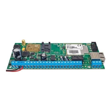
Figure 1. LX2NB Transmitter with LX-ZAS
a) Connections o wires shall be made with due care to prevent any aults or dead
shorts. Places o connections shall be protected against weather conditions.
a) According to the above igure terminals o transmitter shall be connected to:
Terminal Connection descri tion
T1 – R1 Connection to alarm control panel phone communicator
GND Device ground, common or other input and output
LX2NB Manual v.1.3 Page 9 / 57
IN1 - IN4 Signal inputs. Possible connection o detectors contacts or
alarm control panel outputs. GND terminal is common or
all inputs.
OUT1 Type OC output.. It may control external device. Provides
ground during activation.
V+
Connect to the positive pole (+13,8V) o the EBS power
supply.
GND Connect to the negative pole o the power supply.
A ter care ul connections examination a battery may be connected (to +/- AKU
terminals o LX-ZAS power supply) and then power may be switched on or
trans ormer and programming procedure o transmitter may begin (see Chapter 6).
Manufacturer reserves the right to amend a earance of rinted circuit
with no effect on functionality of device.
3.2. INPUT CONFIGURATION
Inputs IN1 - IN4 might work as normally closed (NC) or normally open (NO).
Additionally inputs might be con igured as end o line (EOL-NO or EOL-NC) with
resistors 2,2kΩ or as double end o line (DEOL-NO or DEOL-NC) with resistor 1,1kΩ.
Figure 2. Configuration of input lines
LX2NB Manual v.1.3 Page 10 / 57
3.3. REMOTE CONTROL CONFIGURATION (ONLY LX2NB-5R
VERSION)
The device in version LX2NB-5R provides 2 additional virtual inputs that can be
triggered by radio transmitters. The way o unctioning should be con igured by
GPRS con igurator so tware.
Remote control rogramming rocedure
Press PROG (B) and hold. A ter a moment, the red LED STATUS lash. I the button
is held longer, the red LED STATUS will lash second time and a third and then stop
blinking which would mean the exit rom the programming process.
I the button will be released:
• A ter the irst STATUS LED lash, the transmitter will enter the programming
mode the channel is responsible or virtual input # 5. Status LED on. Pressing the
remote control button program in the transmitter memory. LED turns o to exit the
programming mode.
• A ter the second STATUS LED lash, the transmitter will enter the
programming mode the channel is responsible or virtual input # 6. Status LED on.
Pressing the remote control button program in the transmitter memory. LED turns
o to exit the programming mode.
• A ter the third STATUS LED lash, the transmitter will enter the erasing mode.
Press the PROG button again and wait to LED STATUS o . Release the button.
Erasing o pre-programmed remotes will be con irmed by lighting up STATUS LED
and OK.
3.4. LX-ZAS POWER SUPPLY
The dedicated power supply LX-ZAS (product o EBS) possesses the ollowing
parameters:
Parameter Value
Served batteries Acid-leaded 12V
Maximum voltage o charging battery 13.8V
Charging current 0.2A or 1A (switched by jumper)
Voltage o signaling o low level 11 V
Voltage o switch-o battery 9.5V
as well as it characterizes with ollowing proprieties:
 protection against opposite connecting battery.
 protection against excessive unloading battery:
The battery protects be ore damage in case o long-lasting ading the AC. In
case o lack the AC and unloading below voltage 9.5 V the battery becomes
separated rom device automatically.
 quick charging o the battery:
LX2NB Manual v.1.3 Page 11 / 57
The jumper showed on drawing place causes settlement o maximum
current o charging on 1A. We recommended jumper be taken o and the
current o charging battery carries out 0.2 A.
Figure . Choice of current of charging the battery
Note: the applying the quick charging can bring to damage of battery.
Jumper ON => charging current 1A
Jumper OFF => charging current 0,2A
LX2NB Manual v.1.3 Page 12 / 57
4. QUICK START PROCEDURE
NOTE :
Do not insert SIM card before the first rogramming of transmitter as it
may block the card if PIN code is required for the card.
This cha ter is ur osed for users that ossess ex erience regarding GPRS
data transmission systems and who work with OSM.2007 receiver for
monitoring system. Other users shall ski this cha ter and go to cha ter 5
of this Manual.
As many users possess protected acilities spread at vast locations, local
programming o transmitter is not always available (with PC computer and
programming cable).
Two phases comprise programming in this option:
a) sending to transmitter o main parameters (with SMS) that enable connection
to receiver (OSM.2007 system).
b) ull con iguration o device with remote programming (GPRS transmitter
con igurator and OSM. 2007).
Quick start procedure:
a) insert into device SIM card with PIN code 1111
b) connect power supply or module
c) send to SIM card number with SMS parameters related to connection o
device to receiver (OSM. 2007)
d) waiting or moment, when device indicates connection to OSM.2007
e) complete, remote programming with GPRS transmitter con igurator
Note: Connection to receiver is possible i the device was registered into it.
Registration procedure has been described in OSM.2007 Operation Manual.
SMS text message shall provide the ollowing in ormation:
<transmitter’s service code>█SERVER=<server address>█PORT=<server port>█
APN=<access point name>█UN=<user ID number>█
PW=<user password>
Where:
█: space (every parameter shall be separated with space – blank character)
<transmitter’s service code>: actory settings -1111
<server address>: address o communication server purposed or collection o
transmitter signals e.g. 89.123.115.8. In case address is provided as domain e.g.
block.autostrada.com, SMS message shall include DNS1 parameter (address o main
DNS server)
<server port>: Number o port in server that receives messages rom a device
<access point name>: de ines access point name to GSM network.
I private network is used, SMS message shall provide the ollowing parameters:
UN=<user ID number> and PW=<user password>.
LX2NB Manual v.1.3 Page 13 / 57
Exemplary SMS is as ollows (i we use public network and provide server address
as IP):
1111
█
SERVER=89.123.115.8
█
PORT=6780
█
APN=general.t-mobile.uk
█
UN=
█
PW=
Where:
█:
space character
5. OPERATION
A device maintains communication via GSM-GPRS network. I any problem
ollows a device automatically switch to SMS mode (i this mode has been
programmed be ore – See chapter 7). As a result the transmitter may be used only
at the territory covered with mobile phone operator network.
I status o inputs is the same as programmed one (NO, NC, EOL-NO, EOL-
NC, DEOL-NO, DEOL-NC) a device stays in a rest. Change o status on any input
results in immediate signal transmitting o this event by the device.
Note :
Each input (I 1 – I 4) may be individually defined as normally open ( O) or
normally closed ( C). It means that when input was defined as O, input shorting
will be an active state and when input was defined as C, input opening will be an
active state. EOL and DEOL (parametrized and double parametrized) are options
where you use 1 or 2 resistors to distinguish alarm from sabotage.
To avoid an excessive cost o use related in particular to alse alarms a device
possesses a programmable analysis o inputs.
All inputs respond only to states change which means that transmitting will
ollow only i an active state is on input and maintains during programmed minimum
time. Maintenance o active state longer than a minimum time will result in single
indicating. Another input activation (another transmitting) is possible only a ter
input reached based state.
Number o messages sent in SMS mode is limited (limit includes also text massages
or answers to orders sent by user).This unction provides or cost reduction by
limiting messages e.g. in case o damage o sensor connected to any input. A ter
passage o programmed time new messages will be sent but only in a number
determined by the user.
Text message on events sent to private phone numbers may be edited.
LX2NB transmitter is equipped with input to connect telephone communicator
module o alarm control panel.
Con iguration o transmitter or cooperation with an control panel’s phone
communicator requires entering into memory a phone number or which transmitter
is to answer.
Once a phone is picked up via an alarm control panel telephone
communicator , a telephone number is being dialled to make connection. A ter the
control panel dialled a number to which transmitter is to respond, a transmitter
generates con irmation signal and awaits or data rom a control panel –next DTMF
LX2NB Manual v.1.3 Page 14 / 57
tones generated with communicator are treated as data. A ter transmitting
adequate number o DTMF signs (16 or ContactID and 9 or Ademco FAST)
transmitter generates Kisso signal. Collection o data rom control panel inishes at
hanging up a phone o a control panel by phone communicator module. A ter that
transmitter comes back to standard operation and awaits or dialling o new
number.
I telephone number dialled with communicator is other than number GPRS
module answers, no operation ollows and it waits until communicator hangs up a
phone and picks it up again – since picking up a telephone number dialled with a
communicator module is being checked.
All programmable parameters are saved in memory and in case o voltage
drop that are not lost. Supply o power starts the transmitter with saved settings.
LX2NB Manual v.1.3 Page 15 / 57
6. CONFIGURATION PROGRAM
6.1. INITIAL REMARKS
GPRS transmitters configurator may be downloaded at www.ebs.pl (login: ebs,
password: ebs)
To install program an installation wizard shall be started that per orms installation
in de ault place C:\Program Files\EBS\. During installation process shortcuts on
screen and Windows menu may be created.
I device is to be used or the irst time it shall be programmed with the
above program and a ter this procedure the SIM card may be inserted into the
device. Otherwise SIM card may be blocked i wrong PIN code is entered.
Alternatively SIM card may be used along with switched o PIN code.
In case o remote programming it is necessary to insert SIM card prior to
sending con iguration settings. In this situation SIM card with switched o PIN code
shall be used or be ore card inserting, PIN code shall be changed with mobile phone.
6.2. COMPUTER – REQUIREMENTS
Minimum requirements or computer system where con iguration so tware is to be
installed :
Hardware:
oProcessor Pentium II 400 MHz,
o64 MB RAM,
o1 GB HDD,
oCD-ROM,
oRS-232 serial port,
oColour monitor (minimum 15 inch , min. 800x600 resolution),
oKeyboard,
oMouse
Software:
oOperation system: Windows 2000, Windows XP, Windows Vista or Windows 7
oNET Framework 2.0 (delivered along with installation wizard o con iguration).
6.3. PROGRAM FUNCTIONS
A ter installation and program starting a main view shall be displayed on screen.
Thanks to this view an access to program or programmable parameters o device is
possible (See chapter 7Błąd! Nie można odnaleźć źródła odwołania.).
Main window o program is divided into some ields.
LX2NB Manual v.1.3 Page 16 / 57
Main menu: at upper part o window, contains control and con iguration options.
Main menu contents:
Main menu is available as icons on ast access bar:
6.3.1. File->New
Opens new set o parameters. Editing o con iguration parameters is possible.
Select type o device (LX2NB).
6.3.2. File->O en
I ile contains saved settings, they may be used to program next device. Firstly a
catalogue where ile has been saved shall be chosen and then name o ile shall be
provided. Obtained data collection may be modi ied by the user. Any amendments
are e ective i send to device.
LX2NB Manual v.1.3 Page 17 / 57
6.3.3. File->Save
During programming many devices in di erent con igurations, it is not necessary to
have in mind each one as it may be saved on hard disc or loppy disk under any
name and it may be loaded later on. This unction save on disc any in ormation rom
con iguration wizard window. A ter activation o unction a dialog window appears
with request to provide ile name. De ault data is saved with CMI extension
(Con iguration Memory Image).
6.3.4. File->Language
Allows or selection o any available languages (determined in attached exterior
language iles).
6.3.5. File->Connections
Be ore programming o devices, a connection type shall be de ined. It is possible to
do it with two methods:
- locally
- remotely.
6.3.5.1. Local connection
Local connection means that con iguration so tware (namely computer on which is
installed) is directly connected to proper terminal o transmitter. Connection is
possible owing to special wire and through RS-232 serial port.
To program device or make any other operations (e.g. reading o device settings,
irmware amendments, etc.) it is necessary irstly to de ine connection parameters.
It is possible to do so with the above window that is available a ter activation o
connection rom Main Menu and selection Con iguration tab or a ter clicking on
icon on ast access bar and clicking on RS-232 tab.
De ine:
Name o connection e.g. Local
Choose serial port e.g. COM3
LX2NB Manual v.1.3 Page 18 / 57
Click on [Add] button to con irm settings. Connections shall be saved (and inserted
in table). From this time on program shall enable wires connection with device and
reading, and saving o parameters in LX memory will be possible.
6.3.5.2. Remote connection
As provided above the device and so tware makes or complete con iguration with
GPRS link or CSD channel. This programming mode requires de inition o linking
parameters.
GPRS link
Activate ile in Main menu and select Connection unction (or a ter clicking on
icon on ast access bar) and click on GPRS tab to carry out con iguration o this
mode.
On screen the ollowing window shall appear:
De ine:
 Name o connection e.g.: Remote
 Select name o analyzer e.g.: Primary
 Enter analyzer address e.g.: 87.128.125.8
 Enter port on which analyzer operates e.g. 7000
Click on [Add] button to con irm settings. Connections shall be saved (and inserted
in table). From this time on program shall enable remote connection to device and
reading and saving o parameters in LX memory shall be possible.
Notice: The following arameters: analyzer name, analyze address, ort
relate to settings of OSM.2007 receiver of monitoring system. Remote
rogramming is available only if above mentioned device (or software) is
used.
CSD link
Activate ile in Main Menu and select Connection unction (or a ter clicking on
icon on ast access bar) and click on GSM Modem tab to carry out con iguration o
this mode.
On screen the window shall appear where it is possible to de ine:
 Name o connection e.g. Remote CSD
 Serial port where GSM modem is connected (e.g. Wavecom Fastrack)
 PIN code o SIM card installed in GSM modem e.g. 1111
LX2NB Manual v.1.3 Page 19 / 57
 Serial port parameters: amount o bytes/sec. (e.g. 115200), data bytes (8),
parity (none), stop bytes (1)
Click [Add] button to con irm settings and save connection (settings are inserted
into table). Since that time a remote connection to device, reading and saving o
parameters in LX memory is possible.
Note : Remote con iguration with CSD channel is possible i option o CSD data
sending has been activated both or SIM card inserted into a device and SIM card
installed in GSM modem. In addition, the transmitter must have turned on
permission to receive CSD data calls, see clause 7.5.2 .
Programming with CSD is also possible i OSM.2007 system has been installed, and
minimum one GSM modem is connected. I device has been entered onto server list
( actory number and SIM card telephone number –See OSM.2007 Operation
Manual) it is possible to use link via OSM. It is possible i device is not connected to
the OSM.2007 via GPRS. During programming procedure (with GPRS link- See
above) a question will be displayed i user want to use a modem connected to the
server. A ter con irmation procedure will ollow as in case o other programming
channels.
6.3.6. File->Automatic device settings backu
All con iguration settings including reread rom devices and saved on devices are to
be automatically saved on hard disc. I during installation on con iguring tool
settings have not been changed, iles will be saved as ollows:
C:\Program Files\ EBS\Kon iguratorLX\con igs\LX2NB_20000
Catalog LX2NB_20000 contains all iles in respect o LX2N with actory number o
20000 programming. The name contains date and time o operation and its type
(saving/ reading). Files have cmi extension.
6.3.7. File->Exit
Finishes program operation.
LX2NB Manual v.1.3 Page 20 / 57
6.3.8. O erations->Read
Function reads data saved in memory o GPRS module. Exchange o data ollows on
port selected in section “Select Connection Type” (See below description o option
”Con iguration”). Correct reading is con irmed with message on a screen. Data
downloaded rom device may be saved on ile (see clause 6.3.3) and use or other
devices.
To use this unction it is necessary to de ine type and parameters o connection.
E.g. or local connection the ollowing view is displayed:
where:
Connection kind - serial port to which module is connected
Access code- service code o transmitter
Detailed description o connections con iguration is included in clause 6.3.5.
6.3.9. O erations->Send
This unction is analogical to the above one, at the same time it enables data saving
into EEPROM module. There is also possibility to set correct time into LX device.
Correct saving is con irmed with message on a screen.
6.3.10. O erations->Restore default settings
I operation “Read” inishes with error message (e.g. i access code is unknown) it is
possible to come back to de ault settings by selecting “Restore de ault settings”. e
“Do you want to overwrite current con iguration with de ault values?”. A ter
con irming the ollowing window shall appear:

Other manuals for LX2NB

1

Other EBS Transmitter manuals

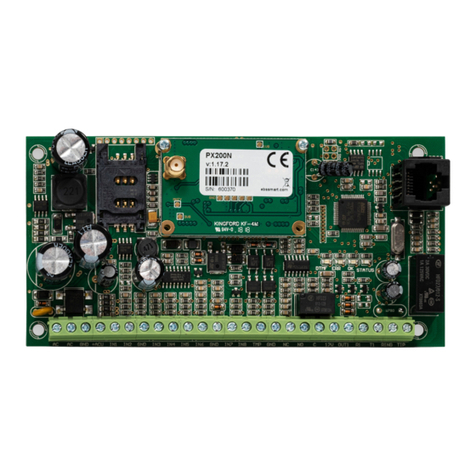
EBS LX1NB-5L Assembly instructions

EBS

EBS LX1NB-5L Assembly instructions

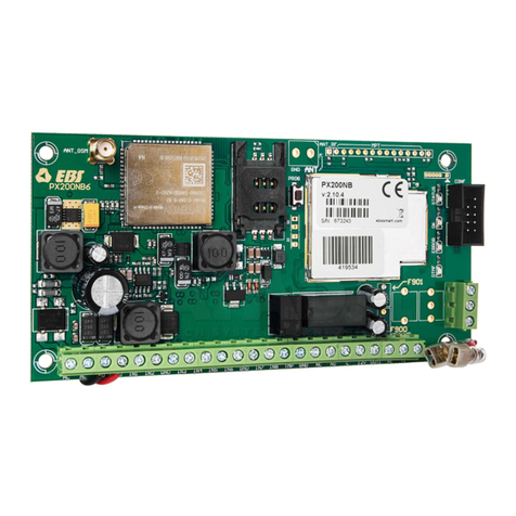
EBS PX200NB Assembly instructions

EBS

EBS PX200NB Assembly instructions

EBS LX2N Assembly instructions

EBS

EBS LX2N Assembly instructions

EBS LX20G Assembly instructions

EBS

EBS LX20G Assembly instructions

EBS LX20B Assembly instructions

EBS

EBS LX20B Assembly instructions

EBS LX1NB-5L Assembly instructions

EBS

EBS LX1NB-5L Assembly instructions

EBS LX2NB Assembly instructions

EBS

EBS LX2NB Assembly instructions

EBS EPX400-5C Assembly instructions

EBS

EBS EPX400-5C Assembly instructions

EBS PX200N Assembly instructions

EBS

EBS PX200N Assembly instructions

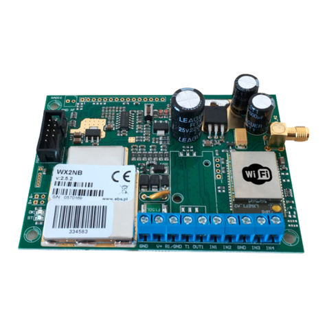
EBS WX2NB Assembly instructions

EBS

EBS WX2NB Assembly instructions

EBS EPX400 Assembly instructions

EBS

EBS EPX400 Assembly instructions

Popular Transmitter manuals by other brands

Kannad 406 AF-COMPACT installation manual

Kannad

Kannad 406 AF-COMPACT installation manual

M-system Mini-M M2XM2 instruction manual

M-system

M-system Mini-M M2XM2 instruction manual

Nokia Treasure Tag user guide

Nokia

Nokia Treasure Tag user guide

KERN YKV-01 Operating and installation instructions

KERN

KERN YKV-01 Operating and installation instructions

M-system MLV instruction manual

M-system

M-system MLV instruction manual

CloviTek CloviFi installation guide

CloviTek

CloviTek CloviFi installation guide

Pico Macom PFT-10 Specifications

Pico Macom

Pico Macom PFT-10 Specifications

Polar Electro WearLink 31 user manual

Polar Electro

Polar Electro WearLink 31 user manual

WIKA R-1 operating instructions

WIKA

WIKA R-1 operating instructions

MG BR instruction manual

MG

MG BR instruction manual

TESTO 6781 instruction manual

TESTO

TESTO 6781 instruction manual

FUTABA R3008SB manual

FUTABA

FUTABA R3008SB manual

ET NICE WAVE instructions

ET NICE

ET NICE WAVE instructions

Burkert 8225 Operating instructions manual

Burkert

Burkert 8225 Operating instructions manual

CityGrow CG102IR-AC installation guide

CityGrow

CityGrow CG102IR-AC installation guide

Canon Wireless File Transmitter WFT-E7A instruction manual

Canon

Canon Wireless File Transmitter WFT-E7A instruction manual

M-system Mini-M M2EXT instruction manual

M-system

M-system Mini-M M2EXT instruction manual

Emerson PT4 Operating	 instruction

Emerson

Emerson PT4 Operating instruction

manuals.online logo
manuals.online logoBrands
  • About & Mission
  • Contact us
  • Privacy Policy
  • Terms and Conditions

Copyright 2025 Manuals.Online. All Rights Reserved.