manuals.online logo
Brands
  1. Home
  2. •
  3. Brands
  4. •
  5. MRC
  6. •
  7. Media Converter
  8. •
  9. MRC 0001911 User manual

MRC 0001911 User manual

HO DCC Steam Sound Decoder
with 20 different chuff sounds
with NMRA 8 pin and 9 pin JST connector
Item#0001911
Thank you for purchasing our most advanced DCC locomo-
tive sound decoder. Combined with any DCC System or Tech
6 Sound Controller, our true live capture digital sound de-
coder will make your model railroad come to life.
•Comeswith NMRA 8 pinand 9 pin JSTconnector foreasy
installation
•Adjustable back EMF load control
•20 types of synchronized chuff sounds
•Double chuff enabling
•1.0 amp capacity
•17 different types of whistles
•Programmable individual sound volumes (64-levels)
•Programmable master sound volumes (64-levels)
•Programmable either 2-digit or 4-digit addresses
•Programmable start voltage and top voltage
•Programmable acceleration and decelaration rates
•Programmable 14, 28, 128 speed steps
•Supports full read back of address and CV values
•Advanced speed table control CV67-CV94
•Directionalhead lights
•Mars light and firebox flicker
•28 accessory functions (F1-F28)
•Supports advanced consisting (CV19)
•Supports programming on the main (OPS mode)
•Compatiblewith NMRA DCCstandards
•Complies with Part 15 of FCC Rules
•28 mm speaker included
•Dimensions: 29.50mm x 10.60mm x 5.0mm
PROGRAMMING
This decoder supports all program modes and read back features.
Printed in USA
SPEED TABLE CV67-CV94 FOR 28 SPEED STEPS
When CV29’s bit 4 is set to “1” it will use the speed table formed by CV67-CV94
to control speed (motor voltage). It allows you to setup each speed for all 28
speed steps. First, program CV29 to 18 for short addresses (1-127) or program
CV29 to 50 for long addresses (128-9999) to enable speed table control. Then
select throttle to 28 speed steps and run your loco at speed step 1. Use program
CV on the main to change CV67’s value (1-255) to adjust step 1’s speed. The
kick voltage, CV65 is only applied when the speed step changes from 0 to 1. You
should switch between 0 to 1 many times to check step 1’s speed. When done
with CV67, select speed step 2 and program CV68. CV68’s value must be
greater then CV67’s. When done with CV67-CV94, use read back CV to make
sure their values are in increasing order.
Note: When using MRC Prodigy DCC to program addresses it will automatically
disable the speed table (set CV29’s bit 4 to “0”). Programming CV125 to 1 will
also disable the speed table and re-program CV67-CV94 to a default linear
speed setting.
TROUBLESHOOTING
Loco running without chuff sound click F12. Whenever the decoder doesn’t
work please use the program track to program CV #125 with value 1 to restore
the decoder to factory settings. This should bring the decoder to life with
address #3. This decoder should perform well with all DCC systems. The maximum
DCC output should be less than 18 V. If the locomotive does not respond to
commands, it may have lost its address. Please re-program the address and
program CV19 to 0 (disable consist). If it responds slowly, you should clear its
momentum by reprogramming CV3 and CV4 to zero. If step 1’s speed is too high,
you should program start voltage, CV2 to zero. If its top speed is too slow, program
top voltage CV5 to 31.You should also clean the track to improve electrical pickup.
Read your DCC system manual to learn how to program and operate the decoder.
For more information about registers/CVs and their functions, please refer to the
NMRADCC Standard & Recommended Practices, RP-9.2.2. This is available
directly from the NMRA or their website at www.nmra.org.
FCC COMPLIANCE
This device complies with part 15 of the FCC Rules. Operation is subject to the
following two conditions. (1) This device may not cause harmful interference, and (2)
This device must accept any interference received, including interference that may
causeundesiredoperation.
RETURNPROCEDURE
This decoder carries a 6 month warranty against factory defects. This warranty does
not include abuse, misuse, neglect, improper installation, or any modifications made
to this decoder, including but not limited to the removal of the NMRA plug if applicable.
If it should become necessary to return the decoder for warranty repair/replacement,
please include a copy of the original sales receipt. Please include a letter (printed
clearly)withyourname, address, daytimephonenumber,and a detaileddescription of
the problem you are experiencing. Please also include a check or a money order for
$11.00 to cover return shipping and handling. If the decoder is no longer considered
under warranty, then please include a check or a money order for $50.00 to cover the
cost of repair or replacement and return shipping and handling. Be certain to return
the decoder only.
Any questions regarding Warranty Policy can be directed to our Customer
Service Department by calling 732-225-6360 between the hours of 8:30am
and 6:00pm EST, or by emailing: rrtech@modelrectifier.com
Send the decoder to: Model Rectifier Corporation
Attn: Parts & Service
80 Newfield Avenue
Edison, NJ 08837-3817 U.S.A
CV Range Default
CV1 1-127 3
CV2 0-32 10
CV3 0-32 0
CV4 0-32 0
CV5 0-32 32
CV29 --- 2
CV7 --- 19
CV8 --- 143
CV17 192-231 192
CV18 0-255 3
CV19 0-127 0
CV21 0-1 0
CV49 0-63 63
CV50 0-17 4
CV51 0-63 60
CV52 0-7 60
CV53 0-63 3
CV54 0-50 10
CV55 0-9 0
CV56 0-63 60
CV57 0-63 40
CV58 0-63 60
CV59 0-63 60
CV60 0-63 60
CV61 0-63 60
CV62 0-63 60
CV63 0-63 60
CV64 0-63 60
CV65 0-63 63
CV67-94 1-255 linear
CV112 0-3 3
CV113 0-31 20
CV114 0-31 10
CV115 0-1 1(enable)
CV116 0-63 60
CV117 0-63 60
CV118 0-63 60
CV120 0-60 30
CV121 0-10 3
CV122 0-1 1(enable)
Description
Short address
Start voltage
Acceleration
Deceleration
Top voltage
Basic configuration
Manufacturer version number
Manufacturer ID
Long address upper byte
Long address lower byte
Advanced consist address
Master sound volume
CV21=0, all accessory function will follow its own address.
CV21=1, all functions will follow the consist address
Whistle type
Whistle volume
Bell type
Bell volume
Bell ring rate
Chuff type (10 types)
Chuff volume
Brake squeal volume
Air release volume
Blower hiss volume
Fire box door volume
Water injector volume
Coupling volume
Water filling volume
Rail clack volume
Kick start voltage
28 speed steps table while CV29.4=1
Metal crank volume
Back EMF Load control proportional gain Kp
Back EMF Load control integral gain Ki
Auto brake squeal enable/disable
Sand drop volume
Shoveling volume
Coal volume
Chuff rate
Chuff start point
Double chuff enable
INSTALLATION
It is quite a challenge to install the decoder in your loco. You should have some
basic electrical knowledge. If you do not , please ask the dealer for help in the
installation.
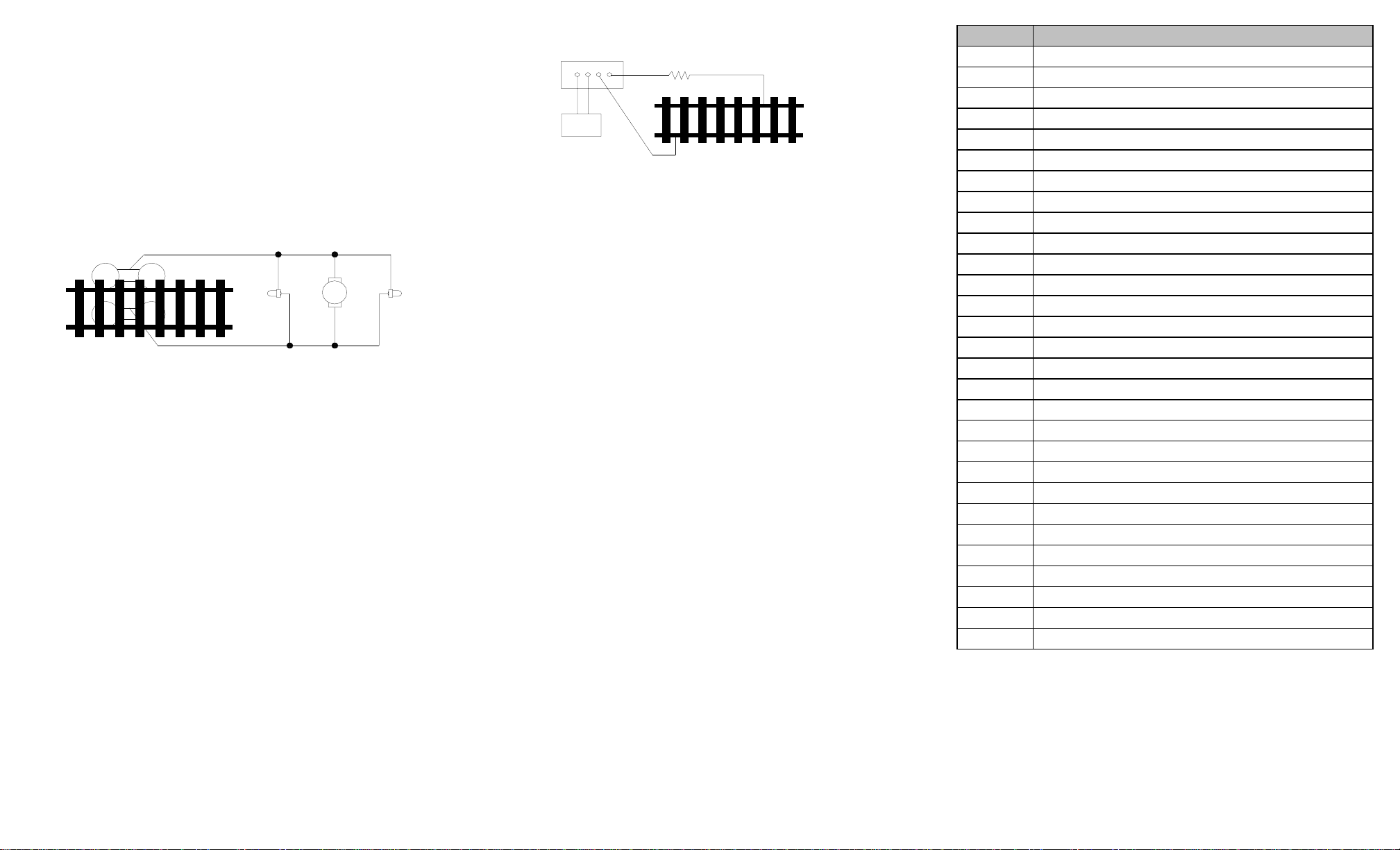
Figure 1 shows the electrical circuit of most standard locos. The terminals of the
motor and lights are directly connected to the wheel pickup. Each type of loco
has its own method of electrical pickup and distribution. There is no standard
rule for installing decoders. It is always better to consult the loco manufacturer
on how to install a decoder in your particular loco. First, figure out your loco’s
electrical wiring and how to disconnect (isolate) the motor and light(s). Label all
wires before you disconnect them.
Figure 1. Connection of standard locomotive. Note: The ‘X’ marks indicate
where to disconnect (isolate).
This decoder is equipped with a wire harness that has an N.M.R.A. 8 pin medium
plug on one end that simply plugs into a dcc ready loco, if you locomotive has a 9
pin JST decoder plug, simply unplug the wire harness of the decoder at the end
of the board and plug the decoder into the 9 pin receptacle.
If your locomotive is not dcc ready and does not have a decoder plug, use the
following directions:
The decoder will be inserted between the wheel pickups and the motor. After
disconnecting the motor terminals from the pickups, connect the right side pickup
wires to the red decoder wire, and connect the left side pickup wires to the
black decoder wire. Connect the right motor terminal to the orange decoder wire,
then connect the left motor terminal to the grey decoder wire.Always use good
soldering techniques, and use shrink wrap to isolate the connections. The white
decoder wire is for the front headlight and the yellow decoder wire is for the rear
light. The blue decoder wire is the light common. The pink and green decoder
wires are for your accessory lights, use the blue decoder wire as the common for
these extra lights. Use double-sided sticky tape to place the decoder in a safe
place. The decoder can’t touch any metal part or bare wires. The 28 mm speaker
should have an enclosure made for a better sound quality.
If you have a 1.5V bulb or LED’s, you should connect a 2k ohm resistor in series to
one of the light leads to limit current.
MAKING A TEST TRACK
We strongly recommend building a test track with a 27 ohm resistor to limit current.
Only test your installed decoder on the test track. The test track will reduce the
chance of damaging your decoder due to an incorrectly installed decoder. Note- The
test track is not your program track.
TESTING
The decoder has been programmed to address #3, 28/128 speed steps.To test,
place the loco on the test track. Select address #3 and 28 speed steps. Move up
the throttle and the loco should move. Push the light button [F0] and headlight
should come on. Change the direction of the loco and the loco should change
direction. The loco cannot reach full speed, due to the resistor. If all the above
occurs, you passed the test. Congratulations! Do not run the loco for an extended
period of time on the test track or the resistor will overheat. If your installed decoder
does not pass the test, find the problem, correct it and test it again. As long as you test
the decoder on the test track there is little chance of damaging the decoder. This is why
the test track is so important.
OPERATION
The decoder has 20 types of chuff sounds (10 single and 10 double). You can
use F24 to select them or F6 to turn the chuff off. With our unique double chuff
enable, (CV122), you can also have 10 articulated chuff sounds. You can use F19 to
select 17 different whistles. You can also use F18 to select 7 different bells. With
MRC ProdigyAdvance2DCC which has 28 functions, you can easily setup and
access all the decoder’s functions. With all other DCC systems you have to use CV
programming to setup the decoder.
BACK EMF LOAD CONTROL (PID CONTROLLER)
This decoder is equipped with adjustable back EMF load control feature. It is a
closed loop speed control. With back EMF load control the locomotive will maintain its
speed regardless of pulling up hill or driving down hill. You may program the back EMF
load control intensity, CV124, to a lower value to get less back EMF load control. This
will enable the locomotive to slow down during uphill travel like real locomotive.
The PID controller contains three components: proportional gain (CV113); the
integral gain (CV114); and derivative gain (fixed). Fine tuning a PID controller is
difficult and experimental on part of the end user, so we optimized these settings
at the factory, but still give the customer the ability to make final adjustments. We
recommend that you do not change these settings. Too much gain may cause the
motor to oscilate (become unstable). Too little gain may cause slow
response. Additional knowledge of PID feedback control is required before
attempting to adjust CV113 and CV114. If CV113 and CV114 are programmed
incorrectly, the locomotive will not run smothly. Program CV125 to “1” will automati-
cally restore the default PID controller settings.
Right side pickup
Front
light Motor Rear
light
Left side pickup
X X
X X X
X
Figure2. Diagram of test track
DCC base unit
Power supply Test track
27 ohm resistor
Function Idle/Moving
F0 Headlight on/off
F1 Bell on/off
F2 Whistle
F3 Accessory lights on/off, Long air release
F4 Coupling 1
F5 Brake squeal (moving) and brake release (idle)
F6 Chuff sound on/off (Drifting) -all other sounds on
F7 Fire box open/close
F8 Water injector
F9 Metal crank sound on/off (moving), steam associated sound (idle)
F10 Water filling
F11 Blower hiss
F12 All sounds on/off
F13 Master volume reduce by 2
F14 Master volume increase by 2
F15 Flange noise
F16 Shoveling
F17 Coal auger
F18 Bell type select (total 7 different ones)
F19 Whistle type select (total 17 different ones)
F20 Air hose firing/uncoupling lever
F21 Flange noise
F22 Associated loco sound
F23 Flange noise
F24 Chuff type select
F25 Long air release
F26 Sand dropping
F27 Associated loco sound
F28 Associated loco sound

Other MRC Media Converter manuals

MRC 0001800 3 User manual

MRC

MRC 0001800 3 User manual

MRC AD324 User manual

MRC

MRC AD324 User manual

MRC 0001952 User manual

MRC

MRC 0001952 User manual

MRC 0001750 User manual

MRC

MRC 0001750 User manual

MRC 0001639 User manual

MRC

MRC 0001639 User manual

MRC 0001805 User manual

MRC

MRC 0001805 User manual

MRC 0001902 User manual

MRC

MRC 0001902 User manual

MRC 0001905 User manual

MRC

MRC 0001905 User manual

MRC 0001802 User manual

MRC

MRC 0001802 User manual

MRC 0001659 User manual

MRC

MRC 0001659 User manual

MRC 0001806 User manual

MRC

MRC 0001806 User manual

MRC 0001819 User manual

MRC

MRC 0001819 User manual

MRC 0001822 User manual

MRC

MRC 0001822 User manual

MRC AD350 User manual

MRC

MRC AD350 User manual

MRC 0001958 User manual

MRC

MRC 0001958 User manual

MRC 0001658 User manual

MRC

MRC 0001658 User manual

MRC 0001910 User manual

MRC

MRC 0001910 User manual

MRC AD370 User manual

MRC

MRC AD370 User manual

MRC 0001956 User manual

MRC

MRC 0001956 User manual

MRC 0001626 User manual

MRC

MRC 0001626 User manual

MRC 0001630 User manual

MRC

MRC 0001630 User manual

MRC 1650 User manual

MRC

MRC 1650 User manual

MRC 0001811 User manual

MRC

MRC 0001811 User manual

MRC 0001628 User manual

MRC

MRC 0001628 User manual

Popular Media Converter manuals by other brands

Seenergy SVD-200 Quick installation guide

Seenergy

Seenergy SVD-200 Quick installation guide

CYP CV-401D Operation manual

CYP

CYP CV-401D Operation manual

Lika Linepuls SME22 Series user guide

Lika

Lika Linepuls SME22 Series user guide

ADF Web HD67954-B2 user manual

ADF Web

ADF Web HD67954-B2 user manual

ATEN UC-232A user manual

ATEN

ATEN UC-232A user manual

TR-Electronic LP-46 Series user manual

TR-Electronic

TR-Electronic LP-46 Series user manual

Planet POE-151 user manual

Planet

Planet POE-151 user manual

CHD Elektroservis SH2/9-M owner's manual

CHD Elektroservis

CHD Elektroservis SH2/9-M owner's manual

Blackmagicdesign Broadcast Converter Operation manual

Blackmagicdesign

Blackmagicdesign Broadcast Converter Operation manual

PTN CSH2 user manual

PTN

PTN CSH2 user manual

WisyCom CSA121 Series quick start guide

WisyCom

WisyCom CSA121 Series quick start guide

Allied Telesis AT-MC1005/2 installation guide

Allied Telesis

Allied Telesis AT-MC1005/2 installation guide

WEISS MEDEA owner's manual

WEISS

WEISS MEDEA owner's manual

Ask Technology HDCN0012M1 user manual

Ask Technology

Ask Technology HDCN0012M1 user manual

CYP CPLUS-VPE2DD Operation manual

CYP

CYP CPLUS-VPE2DD Operation manual

Universal M-400 owner's manual

Universal

Universal M-400 owner's manual

SICK MAX Series operating instructions

SICK

SICK MAX Series operating instructions

Exsys EX-1333VIS manual

Exsys

Exsys EX-1333VIS manual

manuals.online logo
manuals.online logoBrands
  • About & Mission
  • Contact us
  • Privacy Policy
  • Terms and Conditions

Copyright 2025 Manuals.Online. All Rights Reserved.