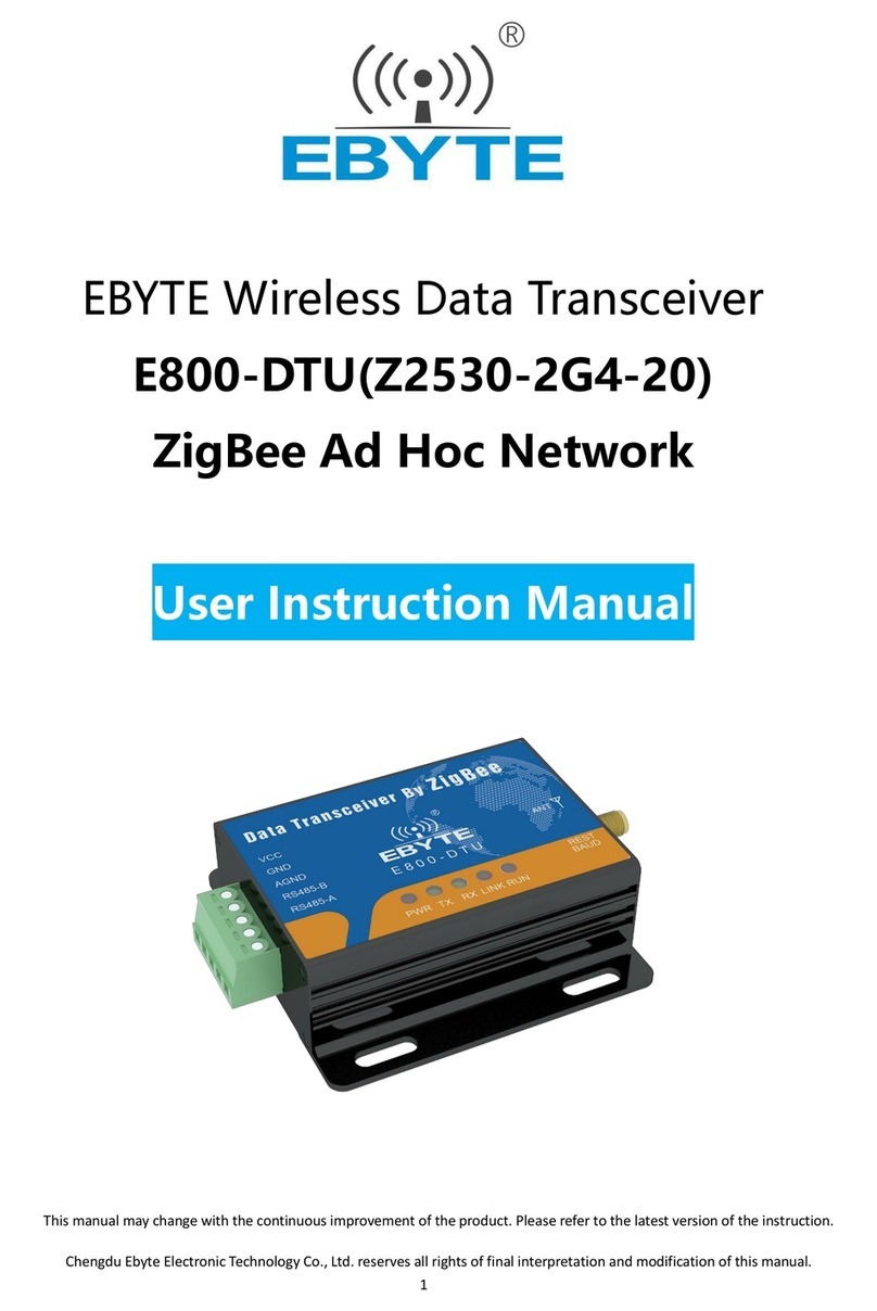
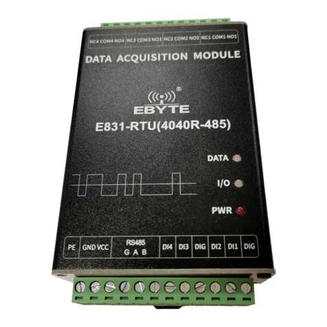
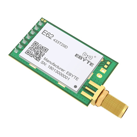
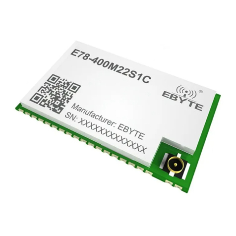
Ebyte E34-2G4H20D User manual

E34-2G4H20D
nRF24L01+ 2.4GHz TTL
Auto Frequency Hopping Module

Chengdu Ebyte Electronic Technology Co.,Ltd. E34-2G4H20D User Manual
Copyright ©2012–2020, Chengdu Ebyte Electronic Technology Co., Ltd.
1
Contents
Contents ····················································································································································································································································1
1. Introduction.............................................................................................................................................................................................................. 2
1.1 Feature............................................................................................................................................................................................................ 3
1.2 Electrical parameter........................................................................................................................................................................................4
1.3 E34 series........................................................................................................................................................................................................5
1.4 FAQ................................................................................................................................................................................................................ 5
2. UART functional description....................................................................................................................................................................................6
2.1 Broadcast transmission...................................................................................................................................................................................6
2.2 Broadcast address........................................................................................................................................................................................... 7
2.3 Monitor address..............................................................................................................................................................................................7
3. Functional description.............................................................................................................................................................................................. 8
3.1 Pin definition.................................................................................................................................................................................................. 8
3.2 Connect to MCU.............................................................................................................................................................................................9
3.3 Reset............................................................................................................................................................................................................... 9
3.4 AUX description.............................................................................................................................................................................................9
4. Operating mode...................................................................................................................................................................................................... 12
4.1 Mode switch................................................................................................................................................................................................. 12
4.2 Fixed Frequency Mode (Mode 0).................................................................................................................................................................13
4.3 Frequency hopping mode (Mode 1)............................................................................................................................................................. 13
4.4 Reservation mode (Mode 2)......................................................................................................................................................................... 13
4.5 Sleep mode (Mode 3)................................................................................................................................................................................... 14
4.6 Quick communication test............................................................................................................................................................................14
5. Instruction format................................................................................................................................................................................................... 15
5.1 Default parameter......................................................................................................................................................................................... 15
5.2 Parameter setting instruction........................................................................................................................................................................ 15
5.3 Reading operating parameters...................................................................................................................................................................... 18
5.4 Reading version number...............................................................................................................................................................................18
5.5 Reset instruction........................................................................................................................................................................................... 18
6. Parameter setting.................................................................................................................................................................................................... 19
7. Customization.........................................................................................................................................................................................................20
Revision history..........................................................................................................................................................................................................20
About us..................................................................................................................................................................................................................... 20
Chengdu Ebyte Electronic Technology Co.,Ltd. E34-2G4H20D User Manual
Copyright ©2012–2020, Chengdu Ebyte Electronic Technology Co., Ltd.
2
Disclaimer
EBYTE reserves all rights to this document and the information contained herein.
Products, names, logos and designs described herein may in whole or in part be subject to
intellectual property rights. Reproduction, use, modification or disclosure to third parties of
this document or any part thereof without the express permission of EBYTE is strictly
prohibited.
The information contained herein is provided “as is” and EBYTE assumes no liability for
the use of the information. No warranty, either express or implied, is given, including but not
limited, with respect to the accuracy, correctness, reliability and fitness for a particular
purpose of the information. This document may be revised by EBYTE at any time. For most
recent documents, visit www.ebyte.com.

Chengdu Ebyte Electronic Technology Co.,Ltd. E34-2G4H20D User Manual
Copyright ©2012–2020, Chengdu Ebyte Electronic Technology Co., Ltd.
3
1. Introduction
1.1 Feature
E34-2G4H20D is a 100mW wireless transceiver module, which operates
at 2.4-2.518GHz. The outstanding advantages of this module is concentrated
power densities, long transmission range, automatic frequency hopping
&strong anti-interference, TTL level.
Automatic frequency hopping technology is in order to ensure the
communication of the secret and anti-interference, compared with fixed
frequency communication, frequency hopping communication is more covert
and difficult to be intercepted. Frequency hopping communication also has a good anti-interference ability, even if there are some
frequency interference, still can communicate on the undisturbed frequency point.
The module has the function of data encryption & compression. The data of the module transmitted over the air features
randomness. And with the rigorous encryption & decryption, data interception becomes pointless. The function of data
compression can decrease the transmission time & probability of being interfered, while improving the reliability & transmission
efficiency.
No.
Feature
Description
1
Frequency
hopping
When the module is in frequency hopping mode, operates automatic frequency
hopping function, compared with fixed frequency communication, frequency
hopping communication is more obscure and difficult to be intercepted.
Frequency hopping communication also has a good anti-interference ability, even
if there are some frequency interference, still can communicate on the
undisturbed frequency point
2
Fixed
transmission
Module can communicate with other modules which work in different channels
and address, easy for networking and repeater.
Module A transmits AA BB CC to module B (address: 0x00 01, channel: 0x80),
HEX format is 00 01 80 AA BB CC (00 01 refers to the address of module B, 80
refers to the channel of module B), then module B receives AA BB CC (only
module B).
3
High-speed
communication
With high air data rate, it features fast communication speed, low delay and big
data packet. This is suitable for those applications requiring low delay and big
data packet.
4
Application
2.4G is free frequency band, so users can use it directly without application.
Because of high frequency and short wavelength, so it’s only suitable for the
open area or the effect decreases in the complicated environment.

Chengdu Ebyte Electronic Technology Co.,Ltd. E34-2G4H20D User Manual
Copyright ©2012–2020, Chengdu Ebyte Electronic Technology Co., Ltd.
4
1.2 Electrical parameter
No.
Item
Parameter details
Description
1
Size
21 * 36mm
Excluding SMA connector
2
Weight
6.7g
Including SMA connector
3
Frequency band
2400 ~ 2518MHz
Default: 2400MHz, Channel:12
4
Process
Lead-free, SMT
-
5
Connector
1 * 7 * 2.54mm
Drop-in
6
Supply voltage
2.3~ 5.5V DC
Note: the voltage higher than 5.5V is forbidden;
7
Communication
level
Maximum 5.2V
Recommended difference between supply voltage is
less than 0.3V to lower power consumption
8
Operation Range
2000m
Test condition:clear and open area&20dBm,
antenna gain: 5dBi ,height:> 2m ,air data rate:
250Kbps
9
Transmitting power
Maximum 20dBm
Four optional level: 20, 14, 8, 2dBm
10
Air data rate
Default 250Kbps
Three optional level: 250, 1000, 2000Kbps
11
Standby current
75uA
M1 =1,M0= 1( Mode 3)
12
Transmitting current
110mA@20dBm
≥250mA (recommended)
13
Receiving current
21.5mA
(mode 0 or mode 1)
14
Driving mode
UART
Can be configured to push-pull/high pull, open-drain
15
Communication
interface
UART
8N1, 8E1, 8O1,
Eight kinds of UART baud rate, from 1200 to 115200
bps
16
Transmitting length
256 bytes
27 bytes per package
17
Receiving length
256 bytes
27 bytes per package
18
Address
4096
Easy for networking, Point to point transmission
(no broadcasting)
19
Wake-on-air
Not supported
-
20
RSSI
N/A
-
21
Antenna type
SMA-K
External thread hole, 50Ω characteristic impedance
22
Operating
temperature
-40 ~ +85℃
-
23
Operating humidity
10% ~ 90%
Relative humidity, no condensation
24
Storage temperature
-40 ~ +125℃
-
25
Receiving
sensitivity
-102dBm@250kbps
Sensitivity has nothing to do with serial baud rate or
timing

Chengdu Ebyte Electronic Technology Co.,Ltd. E34-2G4H20D User Manual
Copyright ©2012–2020, Chengdu Ebyte Electronic Technology Co., Ltd.
5
1.3 E34 series
Model
Interface
Frequency
(Hz)
Power
(dBm)
Operation
range
(km)
Air data
rate
(bps)
Packing
E34-2G4H20D
UART
2.4G
20
2.0
250k~2M
Plug-in
E34-DTU
(2G4H20)
232/485
2.4G
20
2.0
250k~2M
Screwing/ DB9
E34-2G4H20D is compatible with other E34 series
1.4 FAQ
No.
Question
Description
1
Air data rate
Low air rate is recommended, the higher the air rate ,the shorter the range and
higher data loss.
2
Antenna selection
Antenna and module frequency must match with each other, the higher the antenna
gain higher the better, the lowe SWR the better. Sucker antenna is recommended.
3
Messy codes
One reason is serail port baud rate does not match, another one may be due to
inadequate power supply.
4
High delay
Turn off the FEC on both sides, increase air data rate.

Chengdu Ebyte Electronic Technology Co.,Ltd. E34-2G4H20D User Manual
Copyright ©2012–2020, Chengdu Ebyte Electronic Technology Co., Ltd.
6
2. UART functional description
2.1 Broadcast transmission
Format
Values
Fixed transmission format (hexadecimal) for example: FF FF 04 AA BB CC
FF FF are broadcast address; 04 is the channel of target module; AA BB CC are the data to be sent.
Transmitter A
HEX
Address: 00 01; Channel: 02
Receiver B
HEX
Address: 00 03; Channel: 04
Receiver C
HEX
Address: 00 05; Channel: 04
Receiver D
HEX
Address: 00 07; Channel: 06
Module A must be in fixed transmission mode.
Module A sends
HEX
FF FF 04 AA BB CC
Module B receives
HEX
AA BB CC
Module C receives
HEX
AA BB CC
Module D receives
HEX
Null
The receivers under target channel will receive data..
Only 1 data packet length is supported for fixed transmission (refer to electrical parameters);
If the data exceeds 1 data packet length, it will be sub-packed automatically.

Chengdu Ebyte Electronic Technology Co.,Ltd. E34-2G4H20D User Manual
Copyright ©2012–2020, Chengdu Ebyte Electronic Technology Co., Ltd.
7
2.2 Broadcast address
1. For example, set module A address as 0xFF FF and channel as 0x04.
2. When module A is transmitter (transparent mode), all modules with channel 0x04 will receive the data.
2.3 Monitor address
1. For example, set module A address as 0xFF FF and channel as 0x04.
2. When module A is receiver (transparent mode), it with data sent by all modules with channel 0x04.

Chengdu Ebyte Electronic Technology Co.,Ltd. E34-2G4H20D User Manual
Copyright ©2012–2020, Chengdu Ebyte Electronic Technology Co., Ltd.
8
3. Functional description
3.1 Pin definition
Pin
Pin
Pin direction
Pin application
1
M0
Input
(weak pull-up)
Work with M1 & decide the four operating modes.
Floating is not allowed, can be ground.
2
M1
Input
(weak pull-up)
Work with M0 & decide the four operating modes.
Floating is not allowed, can be ground.
3
RXD
Input
TTL UART inputs, connects to external (MCU, PC) TXD output
pin. Can be configured as open-drain or pull-up input.
4
TXD
Output
TTL UART outputs, connects to external RXD (MCU, PC) input
pin. Can be configured as open-drain or push-pull output
5
AUX
Output
To indicate module ’s working status & wakes up the external
MCU. During the procedure of self-check initialization, the pin
outputs low level. Can be configured as open-drain output or
push-pull output (floating is allowed).
6
VCC
-
Power supply 2.3V-5.5V DC
7
GND
-
Ground
8
Fixing hole
-
Fixing hole
9
Fixing hole
-
Fixing hole
10
Fixing hole
-
Fixing hole

Chengdu Ebyte Electronic Technology Co.,Ltd. E34-2G4H20D User Manual
Copyright ©2012–2020, Chengdu Ebyte Electronic Technology Co., Ltd.
9
3.2 Connect to MCU
No.
Description(STM8L MCU)
1
The UART module is TTL level.
2
For some MCU works at 5VDC, it may need to add 4-10K pull-up resistor for the TXD & AUX pin.
3.3 Reset
No.
Description
1
When the module is powered, AUX outputs low level immediately, conducts hardware self-check
and sets the operating mode on the basis of the user parameters. During the process, the AUX keeps
low level. After the process completed, the AUX outputs high level and starts to work as per the
operating mode combined by M1 and M0. Therefore, the user needs to wait the AUX rising edge as
the starting point of module’s normal work.
3.4 AUX description
AUX Pin can be used as indication for wireless send & receive buffer and self-check. It can indicate whether there are data
that are yet to send via wireless way, or whether all wireless data has been sent through UART, or whether the module is still in
the process of self-check initialization.

Chengdu Ebyte Electronic Technology Co.,Ltd. E34-2G4H20D User Manual
Copyright ©2012–2020, Chengdu Ebyte Electronic Technology Co., Ltd.
10
No.
Description
1
【Indication of UART output】can be used to wake up external MCU.
2
【Indication of wireless transmitting】
Buffer (empty): the internal 256 bytes data in the buffer are written to the RFIC (Auto subpackage).
When AUX=1, the user can input data less than 256 bytes continuously without overflow.
Buffer (not empty): when AUX=0, the internal 256 bytes data in the buffer have not been written to
the RFIC completely. If the user starts to transmit data at this circumstance, it may cause overtime
when the module is waiting for the user data, or transmitting wireless subpackage.
Notes: When AUX = 1, it does not mean that all the UART data of the module have been transmitted
already, perhaps the last packet of data is still in transmission.
3
【Configuration procedure of module】
Only happened when power-on resetting or exiting sleep mode.

Chengdu Ebyte Electronic Technology Co.,Ltd. E34-2G4H20D User Manual
Copyright ©2012–2020, Chengdu Ebyte Electronic Technology Co., Ltd.
11
No.
Notes for AUX
1
For function 1 & function 2 mentioned above, the priority should be given to the one with low level
output, which means if it meets each of any low level output condition, AUX outputs low level, if
none of the low level condition is met, AUX outputs high level.
2
When AUX outputs low level, it means the module is busy & cannot conduct operating mode
checking.
Within 1ms since AUX outputs high level, the mode switch will be completed.
3
After switching to new operating mode, it won’t be work in the new mode immediately until AUX
rising edge 2ms later.
If AUX is on the high level, the operating mode switch can be effected immediately.
4
When the user switches to other operating modes from mode 3 (sleep mode) or it’s still in reset
process, the module will reset user parameters, during which AUX outputs low level.

Chengdu Ebyte Electronic Technology Co.,Ltd. E34-2G4H20D User Manual
Copyright ©2012–2020, Chengdu Ebyte Electronic Technology Co., Ltd.
12
4. Operating mode
Contents in below table are the introduction of input status of M1 & M0 and their corresponding mode:
Mode(0-3)
M1
M0
Mode introduction
Remark
Mode 0
Fixed
frequency
mode
0
0
UART and wireless channel are open,
transparent transmission is on.
The receiver must work in
mode 0 or mode 2
Mode 1
Frequency
hopping
mode
0
1
The difference between fixed frequency
mode and frequency hopping mode is: the
frequency will change in send &receive
process according to certain algorithm
rules, the scope is not limited to the basic
frequency of user setting, the module has a
specific spread sequence.
The receiver must work in
mode 1
Mode 2
Reservation
mode
1
0
Reservation mode
Same with mode 0
Mode 3
Sleep
1
1
Parameter setting
-
4.1 Mode switch
No.
Remarks
1
The user can decide the operating mode by the combination of M1 and M0. The two GPIO of MCU
can be used to switch mode. After modifying M1 or M0, it will start to work in new mode 1 ms later
if the module is free. If there are any serial data that are yet to finish wireless transmitting, it will
start to work in new mode after the UART transmitting finished. After the module receives the
wireless data & transmits the data through serial port, it will start to work in new mode after the
transmitting finished. Therefore, the mode-switch is only valid when AUX outputs 1, otherwise it
will delay.
2
For example, in mode 0 or mode 1, if the user inputs massive data consecutively and switches
operating mode at the same time, the mode-switch operation is invalid. New mode checking can
only be started after all the user’s data process completed. It is recommended to check AUX pinout
status and wait 2ms after AUX outputs high level before switching the mode.
3
If the module switches from other modes to stand-by mode, it will work in stand-by mode only after
all the remained data process completed. The feature can be used to save power consumption. For
example, when the transmitter works in mode 0, after the external MCU transmits data “12345”, it
can switch to sleep mode immediately without waiting the rising edge of the AUX pin, also the user’
s main MCU will go dormancy immediately. Then the module will transmit all the data through
wireless transmission & go dormancy 1ms later automatically, which reduces MCU working time
& save power.
4
Likewise, this feature can be used in any mode-switch. The module will start to work in new mode
within 1ms after completing present mode task, which enables the user to omit the procedure of
AUX inquiry and switch mode swiftly. For example, when switching from transmitting mode to
receiving mode, the user MCU can go dormancy before mode-switch, using external interrupt
function to get AUX change so that the mode-switch can be realized.
5
This operation is very flexible and efficient. It is totally designed on the basis of the user MCU’s
convenience, at the same time the work load and power consumption of the whole system has been
reduced and the efficiency of whole system is largely improved.

Chengdu Ebyte Electronic Technology Co.,Ltd. E34-2G4H20D User Manual
Copyright ©2012–2020, Chengdu Ebyte Electronic Technology Co., Ltd.
13
4.2 Fixed Frequency Mode (Mode 0)
When M1 = 0 & M0 = 0, module works in mode 0
Transmitting
The module can receive the user data via serial port, and transmit wireless data package of
29 bytes. When the data inputted by user is up to 29 byte, the module will start wireless
transmission. During which the user can input data continuously for transmission.
When the required transmission bytes are less than 29 bytes, the module will wait 3-byte
time and treat it as data termination unless continuous data inputted by user. Then the module
will transmit all the data through wireless channel.
When the module receives the first data packet from user, the AUX outputs low level.
After all the data are transmitted into RF chip and transmission is started , AUX outputs high
level.
At this time, it means that the last wireless data package transmission is started, which
enables the user to input another 256 bytes continuously. The data package transmitted from
the module working in mode 0 can only be received by the module working in mode 0 or 2.
Receiving
The wireless receiving function of the module is on, the data packet transmitted from the
module working in mode 0 & mode 2 can be received.
After the data packet is received, the AUX outputs low level, 5ms later the module starts to
transmit wireless data through serial port TXD pin.
After all the wireless data have been transmitted via serial port, the AUX outputs high level.
4.3 Frequency hopping mode (Mode 1)
When M1 = 0 & M0 = 1, module works in mode 1.
Transmitting
The condition of data packet transmission & AUX function is the same as mode 0.
The only difference is that the module will according to certain algorithm rules, the
frequency will change in send &receive process, the scope is not limited to the basic
frequency of user setting, the module has a specific spread sequence.
Therefore, the data package transmitted from mode 1 can be received by mode 1
Receiving
The same as that in mode 0.
4.4 Reservation mode (Mode 2)
When M1 = 1 & M0 = 0, module works in mode 2.
Transmitting
The same as that in mode 0.
Receiving
The same as that in mode 0.

Chengdu Ebyte Electronic Technology Co.,Ltd. E34-2G4H20D User Manual
Copyright ©2012–2020, Chengdu Ebyte Electronic Technology Co., Ltd.
14
4.5 Sleep mode (Mode 3)
When M1=1, M0=1,module works in mode 3
Transmitting
Cannot send data
Receiving
Cannot receive data
Parameter
setting
This mode can be used for parameter setting. It uses serial port 9600 & 8N1 to set module
working parameters through specific instruction format.
Notes
When the mode changes from stand-by mode to others, the module will reset its parameters,
during which the AUX keeps low level and then outputs high level after reset completed. It is
recommended to check the AUX rising edge for user.
4.6 Quick communication test
Steps
Operation
1
Plug the USB test board (E15-USB-T2) into computer, make sure the driver is installed correctly.
Plug mode-select jumper in the USB test board (M1 = 0,M0 = 0), make the module work in mode 0.
2
Optional power supply, 3.3V or 5V (it supports 2.3V ~ 5.5V).
3
Operate AccessPort software and select the correct serial port code.

Chengdu Ebyte Electronic Technology Co.,Ltd. E34-2G4H20D User Manual
Copyright ©2012–2020, Chengdu Ebyte Electronic Technology Co., Ltd.
15
5. Instruction format
In sleep mode(mode 3:M1=1, M0=1), it supports below instructions on list.
(Only support 9600 and 8N1 format when setting)
No.
Instruction format
Illustration
1
C0+working parameters
C0 + 5 bytes working parameters are sent in hexadecimal format. 6
bytes in total and must be sent in succession. ( Save the parameters
when power-down )
2
C1 +C1 +C1
Three C1 are sent in hexadecimal format. The module returns the
saved parameters and must be sent in succession.
3
C2+working parameters
C2 + 5 bytes working parameters are sent in hexadecimal format. 6
bytes in total and must be sent in succession. (Do not save the
parameters when power-down )
4
C3 +C3 +C3
Three C3 are sent in hexadecimal format. The module returns the
version information and they must be sent in succession.
5
C4+ C4 +C4
Three C4 are sent in hexadecimal format. The module will reset one
time and they must be sent in succession.
5.1 Default parameter
Default parameter values:C0 00 00 18 00 40
Model
Frequency
Address
Channel
Air data
rate
Baud rate
Parity
Transmitting
power
E34-2G4H20
D
2.4GHz
0xF000
0x00
250kbps
9600
8N1
100mW
5.2 Parameter setting instruction
The difference between C0 command and C2 command is that C0 command will write parameters into the internal flash memory
and can be saved when power down, while C2 command cannot be saved when power down, because C2 command is temporarily
mend instruction.
C2 is recommended for the occasion that need to change the operating parameters frequently, such as C2 F0 00 18 00 40
No.
Item
Description
Remark
0
HEAD
Fix 0xC0 or 0xC2, it means this frame
data is control command
Must be 0xC0 or 0xC2
C0: Save the parameters when power-off
C2: Do not save the parameters when
power-off
1
ADDH
7, 6, 5, 4: resend times (only valid
under mode 0 & 2)
----------------------------------------
3, 2, 1, 0: high address(default F0H)
Default 15 times (default F). Lost data will
be resent.
When multiple same addresses exist,
conflict may occur, please set as 0.
----------------------------------------
Default 0
2
ADDL
Low address of module (default 00H)
(the default 00H)
00H-FFH

Chengdu Ebyte Electronic Technology Co.,Ltd. E34-2G4H20D User Manual
Copyright ©2012–2020, Chengdu Ebyte Electronic Technology Co., Ltd.
16
3
SPED
Rate parameter,including UART baud
rate and air data rate
7,6 UART parity bit
00:8N1(default)
01:8O1
10:8E1
11:8N1(equal to 00)
-----------------------------------------
5,4,3 TTL UART baud rate(bps)
000:1200bps
001:2400bps
010:4800bps
011:9600bps(default)
100:19200bps
101:38400bps
110:57600bps
111:115200bps
----------------------------------------
2, reserved
----------------------------------------
1,0 Air data rate(bps)
00:250(default)
01:1M
10:2M
11:2M (eaqual to 10)
UART mode can be different between
communication parties
----------------------------------------------
UART baud rate can be different between
communication parties
The UART baud rate has nothing to do with
wireless transmission parameters & won’t
affect the wireless transmit / receive
features.
----------------------------------------------
0 is recommended
--------------------------------------
The lower the air data rate, the longer the
transmitting distance, better
anti-interference performance and longer
transmitting time
The air data rate must keep the same for
both communication parties.
10 and 11 are 2Mbps
4
CHAN
7,6,5,4:reserved
-----------------------------------------
3,2,1,0:Channel CHAN(default
0)
Fixed frequency mode(mode 0)
0-5 Communication frequency :
2400M + CHAN * 2M
6-11 Communication frequency :
2508M + (CHAN-6)* 2M
Frequency hopping mode(mode 1)
0-11 Communication frequency :
2412M + CHAN * 2M
0(recommended)
----------------------------------------------
0H-0BH,Totally 12 channels

Chengdu Ebyte Electronic Technology Co.,Ltd. E34-2G4H20D User Manual
Copyright ©2012–2020, Chengdu Ebyte Electronic Technology Co., Ltd.
17
5
OPTION
7,Fixed transmission(similar to
MODBUS)
0:Transparent transmission
mode(default)
1:Fixed transmission mode
-----------------------------------------
6 IO drive mode (default 1)
1:TXD and AUX push-pull
outputs,
RXD pull-up inputs
0:TXD、AUX open-collector
outputs,
RXD open-collector inputs
----------------------------------------
5,4,3,2 reserved
-----------------------------------------
1, 1,0
transmitted power(approximation)
00:20dBm(default)
01:14dBm
10:8dBm
11:2dBm
In fixed transmission mode, the first three
bytes of each user's data frame can be used
as high/low address and channel. The
module changes its address and channel
when transmit. And it will revert to original
setting after complete the process.
----------------------------------------------
This bit is used to the module internal
pull-up resistor. It also increases the level’s
adaptability in case of open drain. But in
some cases, it may need external pull-up
resistor.
----------------------------------------------
0(recommended)
----------------------------------------------
The peak value of the transmitting current
is the current of the data transmission,
current value becomes pointless when it is
not transmitting
The external power must make sure the
ability of current output more than 250mA
and ensure the power supply ripple within
100mV.
For example: The meaning of No.3 "SPED" byte:
The binary bit of the byte
7
6
5
4
3
2
1
0
The specific value
(user configures)
0
0
0
1
1
0
0
0
Meaning
UART parity bit 8N1
UART baud rate is 9600
Air data rate is 250k
Corresponding hexadecimal
1
8

Chengdu Ebyte Electronic Technology Co.,Ltd. E34-2G4H20D User Manual
Copyright ©2012–2020, Chengdu Ebyte Electronic Technology Co., Ltd.
18
5.3 Reading operating parameters
Instruction
format
Description
C1+C1+C1
In sleep mode(M0=1,M1=1),
User gives the module instruction (HEX format): C1 C1
C1,
Module returns the present configuration parameters.
For example, C0 00 00 18 00 40.
5.4 Reading version number
Instruction
format
Description
C3+C3+C3
In sleep mode(M0=1,M1=1),
User gives the module instruction (HEX format): C3 C3
C3,
Module returns its present version number, for example
C3 34 xx yy.
32 here means the module model (E34 series); xx is the
version number and yy refers to the other module features.
5.5 Reset instruction
Instruction format
Description
C4+C4+C4
In sleep mode(M0=1,M1=1),
User gives the module instruction (HEX format): C4 C4 C4, the
module resets for one time.
During the reset process, the module will conduct self-check, AUX
outputs low level. After reset completing, the AUX outputs high
level, then the module starts to work regularly which the working
mode can be switched or be given another instruction.

Chengdu Ebyte Electronic Technology Co.,Ltd. E34-2G4H20D User Manual
Copyright ©2012–2020, Chengdu Ebyte Electronic Technology Co., Ltd.
19
6. Parameter setting
Step
Operation
Description
1
Install Driver
Please install the USB adapter driver (CP2102).
2
Pull out the
jumper
Pull the M0, M1 jumper out, 3.3V or 5V are available for jumper.
3
Connect to
module
Connect the module with USB adapter.
Connect to the USB interface of PC.
4
Open serial
port
Operate the parameter setting software, choose corresponding serial number and
press the “OpenPort”button.
Please choose other serial numbers until open successfully.
5
Interface
Press“Preset”button,the interface will be as below.
If failed, please check if the module is in mode 3, or if the driver has been
installed.
6
Input parameter
Please adjust the parameter as your request according to the corresponding
setting, then click “SetParam”button, write the new parameter to the module.
7
Complete the o
peration
Please operate the “Fifth step”if you need to reconfigure,
if the configuration is completed,
please click "ClosePort" and then take off the module.
8
Commands
Configuration
Parameter configuration is also available for MCU (in mode 3).
This manual suits for next models
3
Table of contents
Other Ebyte Transceiver manuals

Ebyte
Ebyte E70-915T14S Configuration guide

Ebyte
Ebyte Z2530-2G4-20 Operator's manual

Ebyte
Ebyte E90-DTU User manual

Ebyte
Ebyte E90-DTU Operator's manual

Ebyte
Ebyte E90-DTU(433L30E) User manual

Ebyte
Ebyte E810 Series User manual

Ebyte
Ebyte E90-DTU User manual

Ebyte
Ebyte E78-400M22S1C User manual

Ebyte
Ebyte E840-DTU User manual

Ebyte
Ebyte E62-433T20D User manual