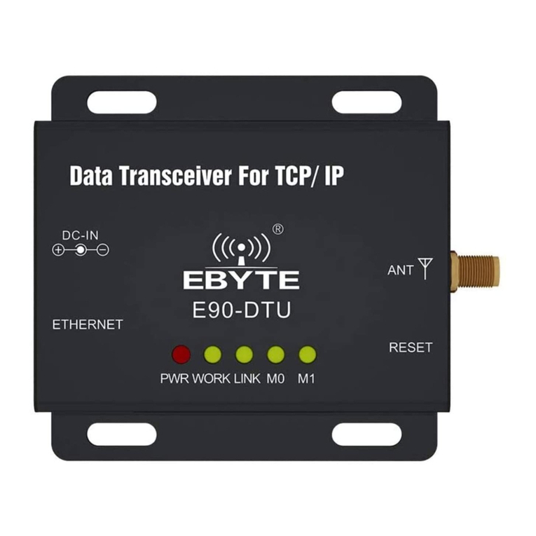
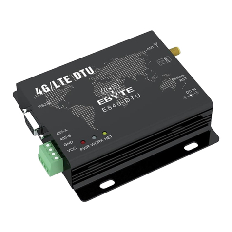
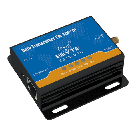
Ebyte Z2530-2G4-20 Operator's manual

1
EBYTE Wireless Data Transceiver
E800-DTU(Z2530-2G4-20)
ZigBee Ad Hoc Network
User Instruction Manual
This manual may change with the continuous improvement of the product. Please refer to the latest version of the instruction.
Chengdu Ebyte Electronic Technology Co., Ltd. reserves all rights of final interpretation and modification of this manual.

2
1. Introduction
1.1 Brief introduction
E800-DTU(Z2530-2G4-20) is a wireless data transceiver based on ZigBee technology with function of transparent
transmission, protocol transmission, AT configuration, etc. Wireless data transceiver working as a communication medium,
as well as the fiber, microwave, the same line, has a certain scope of application: it provides some special conditions in the
private network monitoring signal real-time, reliable data transmission, with the features of low cost, convenient
installation and maintenance, diffraction ability, flexible network structure, range of coverage, suitable for the occasion
of dot and scatter, complex geographical environment , connecting with PLC, RTU, rain gauge, level gauge and other data
terminals.
1.2 Function Features
❖All the core components are imported originally , compared with the current imports of digital transceiver , we are
the most advanced, most cost effective and the smallest one.
❖Transmission power is optional, all technical indicators have met the European industry standards.
❖Use temperature compensation circuit, the frequency stability is better than ±2PPM.
❖With operating temperature range: -40 ℃ ~ +85 ℃, adapting to a variety of harsh working environment.
❖All with aluminum alloy shell, compact, easy installation, good heat dissipation; perfect shielding design, good
electromagnetic compatibility and strong anti-interference ability.
❖Power reverse protection, over-protection, antenna surge protection and other multiple protection functions,
greatly increase the reliability of the transceiver.
❖Powerful software features, all parameters can be programmed to set: such as power, frequency, air data rate,
address ID, etc.
❖Ultra-low power consumption, standby current is 20mA (the power consumption of power saving mode and sleep
mode is lower), the transmitting current ≤ 350A (1W).
❖With watchdog and accurate time layout, in the event of an exception, the module will automatically restart and
continue to follow the previous parameters to operate.
1.3Product Features
No.
Feature
Description
1
Role switch
Users can switch freely between the coordinator, router and end device via UART command.
2
Automatic
Support power-on automatic networking. The coordinator automatically sets up the network, the

3
networking
end device and the router automatically searches and joins the network.
3
Network
self-healing
Automatically reconnect when losing network. When intermediate node in network is lost, other
networks automatically join or maintain the original network. (Isolated nodes automatically join the
original network, non-isolated nodes maintain the original network.)
When the coordinator is lost and non-isolated nodes exist in the original network, the coordinator
can join the network again or coordinator of the original network PAN_ID set by the same user join
the original network.
4
Ultra low power
consumption
The device can be set as low power mode in the end state. Sleep time of the device can be
changed according to the user's using time. The standby power consumption in the low power
mode is less than 2uA. In the father node data storage time, all messages can be received within the
time set by users.
5
Configuration for
data storage
time
When device is in the coordinator and router state, the user can set their own data storage time, and
work with end device in sleep mode to save data for the end device, and sent data to the end device
when it wakes up.
Data saved is up to 3 data packets, if exceeded, it will automatically clear the first data! After the data
is saved, the data heap is automatically cleared.
6
Automatic
retransmission
In unicast mode, the device will automatically retransmit when failed to send to next node, and the
number of retransmission per message is three.
7
Automatic
routing
The module supports network routing. Router and coordinator have network data routing function,
users can conduct multi-hopping networking.
8
Support
encryption
protocol
The module uses AES 128 bit encryption function, can change the network encryption and prevent
monitoring. Users can change the network key by themselves. Only devices with the same network
key can start normal networking communication.
9
Support UART
configuration
Module has built-in UART commands, the user can configure (view) the parameters and functions of
module via UART command .
10
Communication
for various types
of data
Support broadcasting, multicasting and unicasting in the entire network. In the broadcast and
unicast mode, it also supports several transmission methods, please refer to <E18 v1.2
communication protocol> for the details.
11
Change channel
It supports change of 16 channels ranging from 11 to 26(2405~2480MHZ), different channels have
different frequency.
12
Change network
PAN_ID
Free switch of network PAN_ID. Users can define PAN_ID to join the corresponding network by
themselves or automatically select PAN-ID to join the network.
13
Change UART
baud rate
Users can set baud rate by themselves which can be as high as 1M, it is 8 bits by default without
parity bit.
14
Search short
address
Users can find out corresponding short address according to the (unique and fixed) MAC address of
module that already joined network.
15
Command
format switch
The module supports AT command and HEX command for users’easy configuration and switch.
The physical location is P1.6.
16
Module restore
Users can restore the module via UART commands.
17
Onekey recovery
of baud rate
The module supports onekey recovery of baud rate when users forget the baud rate. The baud rate
is 115200(default), physical location is P1.7.
18
Recover factory
setting
Users recover the factory setting via UART commands.

4
2. Installation Dimension
2.1 Pin description
Pin NO.
Name
Function
Description
1
3.81mm terminal block
UART interface/
Power supply interface
Standard RS-232&485 interface/
Screwing power supply interface
2
PWR-LED
Power LED
Red, lit when the power is on
3
TX-LED
Transmit LED
Yellow, blinks when sending data
4
RX-LED
Receive LED
Yellow, blinks when reveiving data
5
LINK-LED
Link LED
Red, lit when no network, off when
network connected
6
RUN-LED
Run LED
Red, system operating Indicator, lit
when running error, off when
running properly
7
Baud Rate Reset
Tact switch
Reset baud rate(115200)
8
Antenna interface
SMA-K interface
External thread, 10mm, 50Ω
characteristic impedance

5
2.2 Dimension

6
3. Interface definition
3.1 Power interface definition
Users can choose ① the VCC and GND terminal power supply, E800-DTU(Z2530-2G4-20) can use 8~ 28V DC power
supply, but it is recommended to use 12V or 24V DC power supply.
3.2 RS485 interface definition
E800-DTU(Z2530-2G4-20) uses RS485 as communication protocol. How to connect the cable? Choose the
corresponding interface in ① 3.81mm terminal block, details below:
Pin NO.
Definition
Function
Description
1
VCC
Screwing power interface, positive
8 ~ 28V DC, 12V or 24V( recommended )
2
GND
Screwing power interface, negative
The power supply negative pole is connected
to the system ground and the housing
3
AGND
Public ground
Connected to ground of other devices or not
connection
4
RS485-B
Serial port terminal
RS-485: Connected to RS 485 device interface B
5
RS485-B
Serial port terminal
RS-485: Connected to RS 485 device interface A
★ Note: The transceiver will be in poor communication when connecting multiple devices , while connecting a single
device is not, please try to parallel connect a 120Ω resistor between 485_A terminal and 485_B terminal.

7
4. Function module
4.1. Operating mode
Mode
Node type
Description
Data communication
display mode
Mode 1
(Transparent
mode)
Coordinator
Serial data will be transmitted to modules not in sheep by broadcasting.
Data format can be
configured by command:
1 Display Mac address of
transmitter
2 Display Mac address of
transmitter
3 Display RSSI value of
message shortest path
(Display mode can be
configured to no display,
one mode display or
multiple modes display)
Router
Serial data will be transmitted to coordinators by point to point.
(Note: Terminal can not receive the data in sleep mode )
Terminal
Mode 2
(Half-transpa
rent mode)
Coordinator
Data will be transmitted according to the fixed format protocol of data
transmission, There are point to point, broadcast, multicast transmission
ways. Please refer to “HEX data communication description“for details.
Router
Serial data will be transmitted to coordinators by point to point.
Terminal
Mode 3
(Protocol
mode)
Coordinator
Data will be transmitted according to the fixed format protocol of data
transmission, There are point to point, broadcast, multicast transmission
ways. Please refer to “HEX data communication description“for details.
None
Router
Terminal
Note:User can only operate Mode 3 to configure GPIO function. Communication between arbitrary modes can communicate with each other
and not affect each other。
4.2 Brief introduction of protocol mode
No.
Mode
Description
1
Broadcast
User can broadcast on the whole network according to command when connecting network (3 modes):
1、Mode 1 ——Broadcast to all modules.
2、Mode 2 ——Broadcast to modules in the receiving mode (except sleep mode).
3、Mode 3 ——Broadcast to full function modules (Coordinator and Router).
2
Multicast
Multicast to all modules (not in sleep mode) when connecting network.
3
Point to
point
Module can communicate with other devices by short address according to command when connecting network (3
modes):
1、Transparent transmission ——no information
2、Short address ——the information is short address
3、Mac address ——the information is MAC address
Notes: Please refer to “HEX data communication description“ for details.

8
5. Quick Start
★ Note: programming can only be carried on in a specific mode(see above), if fails, please confirm the work mode.
No.
Notes
1
【Construct network】:
①.Connect Zigbee ad hoc module via USB to UART converter.
②.Open host computer software “Zigbee_Setting_V1.1”, select Com port and set baud rate as 115200(default), then
open port;
③.Click read parameter to read corresponding module parameter.

9
④.Select node type as coordinator, write in parameter. Wait the coordinator to start constructing network and users can
check module parameter.
Set network parameter:(when PAN ID is FFFF, it is automatic PAN ID)
Read parameter when network is constructed:

10
⑤.Select another module, set it as the router or end device following the same steps (module is set as end device when
leave factory (default),no need to set again, in this experiment it is end device )。

11
2
【Communication test】:
①.Click “fixed networking”of the coordinator and end device of the host computer. Corresponding info. is available to be
viewed.
Coordinator:
End device:
②. For users’convenience to observe, in this experiment it is HEX transmitting mode.
If the device address is unknown, please input corresponding mac address and click get network address. The short
address of coordinator is 0.

12
③.Input random content in these 3 modes, click start.
Transparent transmission:
From coordinator to end device:
From end device to coordinator:
Network address:
From coordinator to end device:

13
From end device to coordinator:
MAC address:
From coordinator to end device:
From end device to coordinator:
Multicast:

14
Broadcast :( broadcast only conduct Mode 1, the entire network conduct broadcast mode experiment, other modes test
by themselves )
Data function transmission needs to reflect its own characteristics in the case of multi-node network, the users can test by
themselves!
6. User Command Set
For the convenience of users, E800-DTU(Z2530-2G4-20) has two command formats, AT and HEX, default HEX. In this mode, user
can transmit “+++”with serial port assistant to be in temporary AT command mode, then can configure with AT command and exit AT
command mode by transmitting “AT+EXIT”.
Note:
1. Serial data format error message
HEX command mode: F7 FF
AT command mode: +ERROR<CR><LF>
2. Coordinator building network message
HEX command mode: FF FF
AT command mode: Builded network<CR><LF>
3. Module joining the network message
HEX command mode: FF AA
AT command mode: Joined network<CR><LF>
4. Module no network message
HEX command mode: FF 00
AT command mode: No network<CR><LF>
5. <CR>: 0x0D
6. <LF>: 0x0A

15
6.1 HEX command Set
Description
Format
Example
Read device type
Transmit:FE 01 01 FF
Return:FB dev_type
Transmit:FE 01 01 FF
Return:FB 02
Read network state
Transmit:FE 01 02 FF
Return:FB nwk_state
Transmit:FE 01 02 FF
Return:FB 01
Read network PAN_ID
Transmit:FE 01 03 FF
Return:FB pan_id
Transmit:FE 01 03 FF
Return:FB 02 F4
Read network key
Transmit:FE 01 04 FF
Return:FB key
Transmit:FE 01 04 FF
Return:FB 11 13 15 17 19 1B 1D 1F 10 12 14 16 18 1A 1C 1D
Read local short address
Transmit:FE 01 05 FF
Return:FB ShortAddr
Transmit:FE 01 05 FF
Return:FB F2 EF
Read local Mac address
Transmit:FE 01 06 FF
Return:FB Mac_Addr
Transmit:FE 01 06 FF
Return:FB 89 6C 50 09 00 4B 12 00
Read father node short
address
Transmit:FE 01 07 FF
Return:FB Coor_shortAddr
Transmit:FE 01 07 FF
Return:FB 00 00
Read father node Mac
address
FE 01 08 FF
Return:FB Coor _Mac_Addr
Transmit:FE 01 08 FF
Return:FB 20 39 EA 0A 00 4B 12 00
Read network group no.
Transmit:FE 01 09 FF
Return:FB group
Transmit:FE 01 09 FF
Return:FB 01
Read communication
channel
Transmit:FE 01 0A FF
Return:FB channel
Transmit:FE 01 0A FF
Return:FB 0B
Read transmission power
Transmit:FE 01 0B FF
Return:FB txpower
Transmit:FE 01 0B FF
Return:FB 04
Read serial baudrate
Transmit:FE 01 0C FF
Return:FB baud
Transmit:FE 01 0C FF
Return:FB 09
Read sleep state (vaild for
terminal)
Transmit:FE 01 0D FF
Return:FB sleep_time
Transmit:FE 01 0D FF
Return:FB 05
Read data storage time
(valid for router and
coordinator)
Transmit:FE 01 0E FF
Return:FB 1E
Transmit:FE 01 0E FF
Return:FB 1E
Read all datas
Transmit:FE 01 FE FF
Return:FB all_info
Transmit:FE 01 FE FF
Return:FB 02 01 02 F4 11 13 15 17 19 1B 1D 1F 10 12 14 16 18 1A
1C 1D F2 EF 89 6C 50 09 00 4B 12 00 00 00 20 39 EA 0A 00 4B 12
00 01 0B 04 09 05
Read arbitrary short
address of Mac address
Transmit:FE 09 10 Mac_Addr FF
Return:FB shortAddr
Transmit:FE 09 10 AF 99 E9 0A 00 4B 12 00 FF
Return:FB 08 35
Read remote /local GPIO
input/output state
Command:FE 04 20 addr gpiox
FF
Return:FB 20 addr In/Out
FE 04 20 F9 DE 04 FF
Read remote /local GPIO
input/output level
Command:FE 04 21 addr gpiox
FF
Return:FB 21 addr In/Out level
FE 04 21 FF FF 04 FF

16
Description
Format
Example
Read remote /local PWM
state
Command:FE 04 22 addr 22 FF
Return:FB 22 addr period duty1
duty2 duty3 duty4 duty5
FE 04 22 FFFF 22 FF
Read remote /local ADC
state
Command:FE 04 23 addr pin FF
Return:FB 23 addr adc_value
FE 04 23 FF FF 01 FF
6.2 HEX Parameter Description
Network type
dev_type:00 coordinator
01 router
02 terminal(default)
Network state
nwk_state:00 no network
01 network
Network PAN_ID
pan_id:0000~FFFE fixed network PAN_ID
FFFF random network PAN_ID
Network key
key:16 bytes network key
Network short address
ShortAddr:2 Byte address
Network MAC address
Mac_Addr:8 Byte address
Father node short address
Coor_shortAddr:2 Byte address
Father node Mac address
Coor_Mac_Addr:8 Byte address

17
Network group no.
group:1~99(default 1)
Network chananel
channel:11~26(default 11)
Transmission power
txpower:
txpower contrast with PA / without PA
txpower
power (dBm)
txpower
power (dBm)
00
-3 / 16
03
2.5 / 20
01
-1.5 / 17
04
4.5 / 20 (default)
02
0 / 19
05
Serial baudrate
baud:
baudrate contrast
baud
baudrate
baud
baudrate
00
2400
08
76800
01
4800
09
115200(default)
02
9600
0A
128000
03
14400
0B
230400
04
19200
0C
256000
05
38400
0D
460800
06
43000
0E
921600
07
57600
0F
1000000
Sleep time
sleep_time:0 sleep mode closed(default)
1~250 sleep mode opened sleep time is sleep_time /S (second)
Father node storage time
time:0~120(default 30), unit S(second)
GPIO parameter
(1)GPIO port
gpiox:

18
GPIO contrast
gpiox
00
01
02
03
04
05
06
07
08
09
GPIO
P0_0
P0_1
P0_2
P0_3
P0_4
P0_5
P0_6
P2_0
P2_1
P2_2
For example:When gpio parameter is 2,the pin is P0_2
When gpio parameter is 8,the pin is P2_1
(2)GPIO input/output state
in/out:1 input
0 output
(3)GPIO state value(configuration input state invalid)
level:0 low
1 high
2 flipping
PWM parameter
(1)PWM port
pwmx:
PWM port contrast
pwmx
duty1
duty2
duty3
duty4
duty5
GPIO
P0_2
P0_3
P0_4
P0_5
P0_6
(2)pwm cycle
period:(0~FFFF)
cycle tim(unit 1 = 62.5ns)
(3)pwm duty cycle
dutyx:(0~FFFF):
duty cycle time (unit 1 = 62.5ns)
ADC parameter
(1)ADC channel
adcx:
ADC channel contrast
adcx
0
1
2
3
4
5
6
GPIO
P0_0
P0_1
P0_2
P0_3
P0_4
P0_5
P0_6
(2)adc state value
adc_state:0 ADC enable
1 ADC disable
(3)adc sampling value
adc_value:0~0X0CE4 (0~3300)unit mV

19
Peripherals addr parameter
(1)Peripherals address
addr:
FFFF inquire/configure local info
0~FFF8 inquire/configure info of whose network address is addr
FFFE、FFFD、FFFC inquire/configure info of which received broadcasting data
---FFFE broadcast to all modules
---FFFD broadcast to free modules(except sleeping modules)
---FFFC broadcast to coordinators and routers
All information
(1)all_info:
Identification ( Length (position) ) Description
dev_type (1 Byte(0))Device type
nwk_state (1 Byte(1))Network state
pan_id (2 Byte(2~3)) Network PAN_ID
key (16 Byte(4~20)) Network key
ShortAddr (2 Byte(21~22)) Network short address
Mac_Addr (8 Byte(23~30)) MAC address
Coor_shortAddr (2 Byte(31~32)) Father node short address
Coor_Mac_Addr (8 Byte(33~40)) Father node MAC address
group (1 Byte(41)) Network group no.
channel (1 Byte(42)) Communication channel
txpower (1 Byte(43)) Transmission power
baud (1 Byte(44)) Serial baudrate
sleep_time (1 Byte(45)) Sleep mode
Example for parameter:
all_info:
020102 F411 13 15 17 19 1B 1D 1F 10 12 14 16 18 1A 1C 1DF2 EF89 6C 50 09 00 4B 12 0000 0020 39 EA 0A 00 4B 12 00010B040905
➢Device type:02 (terminal)
➢Network state:01 (existing network)
➢Network PAN_ID:02 F4 (PAN_ID=0X02F4)
➢Network key:11 13 15 17 19 1B 1D 1F 10 12 14 16 18 1A 1C 1D
➢Local short address:F2 EF (Local short Address=0XF2EF)
➢Local MAC address:89 6C 50 09 00 4B 12 00
➢Father node short address:00 00(Short Address=0X0000)
➢Father node MAC address:20 39 EA 0A 00 4B 12 00
➢Network group no.:01 (1)
➢Communication channel:0B (11)
➢Transmission power:04 (4.5dBm)
➢Serial baudrate:09 (115200)
➢Sleep mode:05 (5 seconds)
(Note:Father node storage time is not included,if needs inquire or configuration,please use independent command)

20
HEX communication description
Command format description
(Note:It is applicable only to the nodes in mode 3 or coordinator in mode 2)
Command(COM)1Byte
Length(LEN)1Byte
Data(DATA)
FC
LEN
DATA
Parameter description
DATA parameter description:
(1)Broadcasting data(content to be sent)
command:01+type+data
parameter description:type
01:mode 1 ——broadcast to all modules
02:mode 2 ——broadcast to free modules(except sleeping modules)
03:mode 3 ——broadcast to coordinators and routers
e.g:FC 05 01 02 31 32 33
description:broadcasting HEX data in mode2:0X31 0X32 0X33
(2)Multicasting data(content to be sent)
command:02+ group+data
parameter description:group
0~99:number
e.g:FC 05 02 01 31 32 33
description:transmit HEX data to network group no.1:0X31 0X32 0X33
(3)Point to point transmission(content to be sent)
command:03+ type +addr+data
parameter description:type (for coordinator in mode 2,it’s invalid,it can be set to any value)
01:transparent transmission mode(no info.)
02:short address mode(short message info.)
03:MAC address mode(MAC message info.)
note:addr:network short address valid address: 0x0000—0xFFF8.
e.g:FC 07 03 01 AB CD 31 32 33
description:transmit HEX data point to point with short address to device whose network address is 0XADCD:0X31 0X32 0X33
AT Command Set
AT+DEV
Function:inquire /configure device type
Format:
inquire
transmit:AT+DEV= type
return:+OK<CR><LF>
configure
This manual suits for next models
1
Table of contents
Other Ebyte Transceiver manuals

Ebyte
Ebyte E90-DTU User manual

Ebyte
Ebyte E90-DTU User manual

Ebyte
Ebyte E90-DTU(433L30E) User manual

Ebyte
Ebyte E34-2G4H20D User manual

Ebyte
Ebyte E831-RTU Series User manual

Ebyte
Ebyte E810 Series User manual

Ebyte
Ebyte E90-DTU Operator's manual

Ebyte
Ebyte E62-433T20D User manual

Ebyte
Ebyte E78-400M22S1C User manual

Ebyte
Ebyte E840-DTU User manual