Echo SHC-266 User manual

Specifications, descriptions and illustrative material in this literature are as accurate as known at the time
of publication, but are subject to change without notice. Illustrations may include optional equipment and
accessories, and may not include all standard equipment.
Operator’s Manual
X502026702
© 4/2013 ECHO Inc.
X7722271404 / X772000164
SHC-266
Shaft Hedge Clipper
Burn Hazard
The muffler or catalytic muffler and surrounding cover may become extremely hot.
Always keep clear of exhaust and muffler area, otherwise serious personal injury may
occur.
The engine exhaust from this product contains chemicals known to the State of California to cause
cancer, birth defects or other reproductive harm.
Users of this equipment risk injury to themselves and others if the unit is used
improperly and/or safety precautions are not followed. ECHO provides an operator’s
manual and a safety manual. Both must be read and understood for proper and safe
operation. Failure to do so could result in serious injury.

2X7502026702
© 4/2013 ECHO Inc.
TABLE OF CONTENTS SHC-266
TABLE OF CONTENTS
Table of contents ............................................................................................................................... 2
Introduction ........................................................................................................................................ 3
The Operator’s Manual ................................................................................................................ 3
The Safety Manual....................................................................................................................... 3
Servicing information ......................................................................................................................... 3
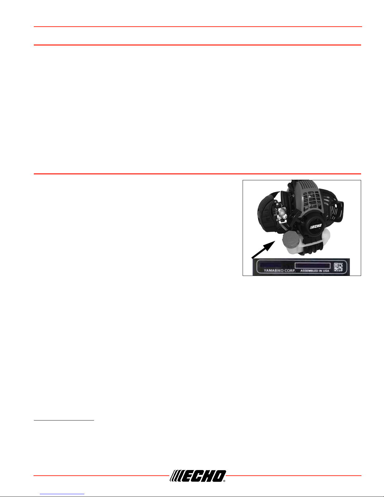
Parts/Serial Number..................................................................................................................... 3
Service......................................................................................................................................... 3
Echo Consumer Product Support ................................................................................................ 3
Warranty Registration .................................................................................................................. 3
Additional or Replacement Manuals ............................................................................................ 4
Safety................................................................................................................................................. 4
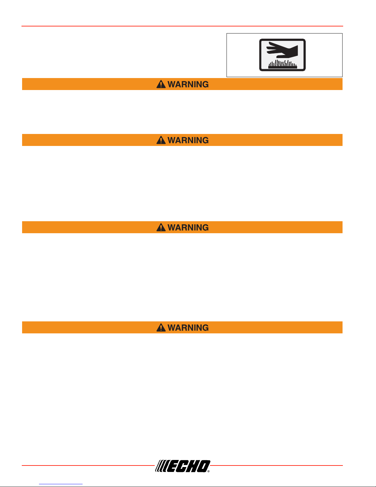
Manual Safety Symbols and Important Information..................................................................... 4
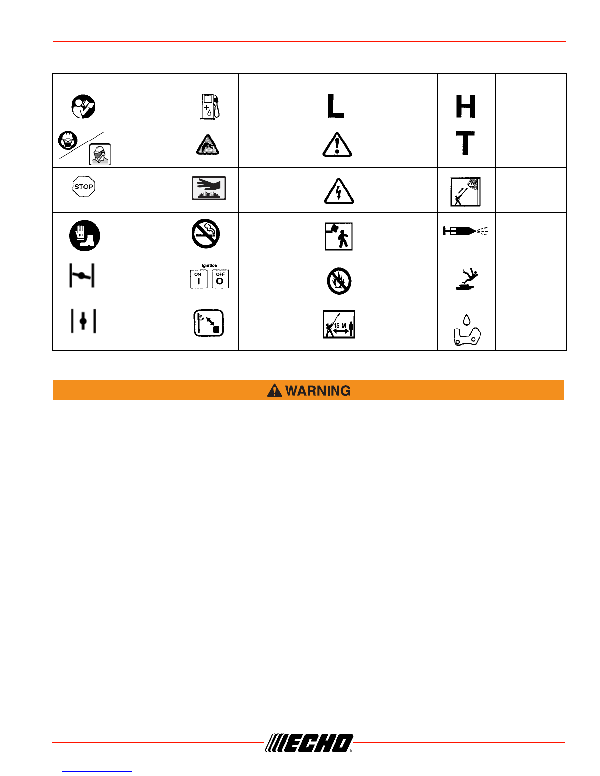
International Symbols .................................................................................................................. 5
Personal Condition and Safety Equipment .................................................................................. 5
Equipment.................................................................................................................................... 8
Emission Control (Exhaust & Evaporative)........................................................................................ 9
EPA 2010 and Later and/or C.A.R.B. TIER III ............................................................................. 9
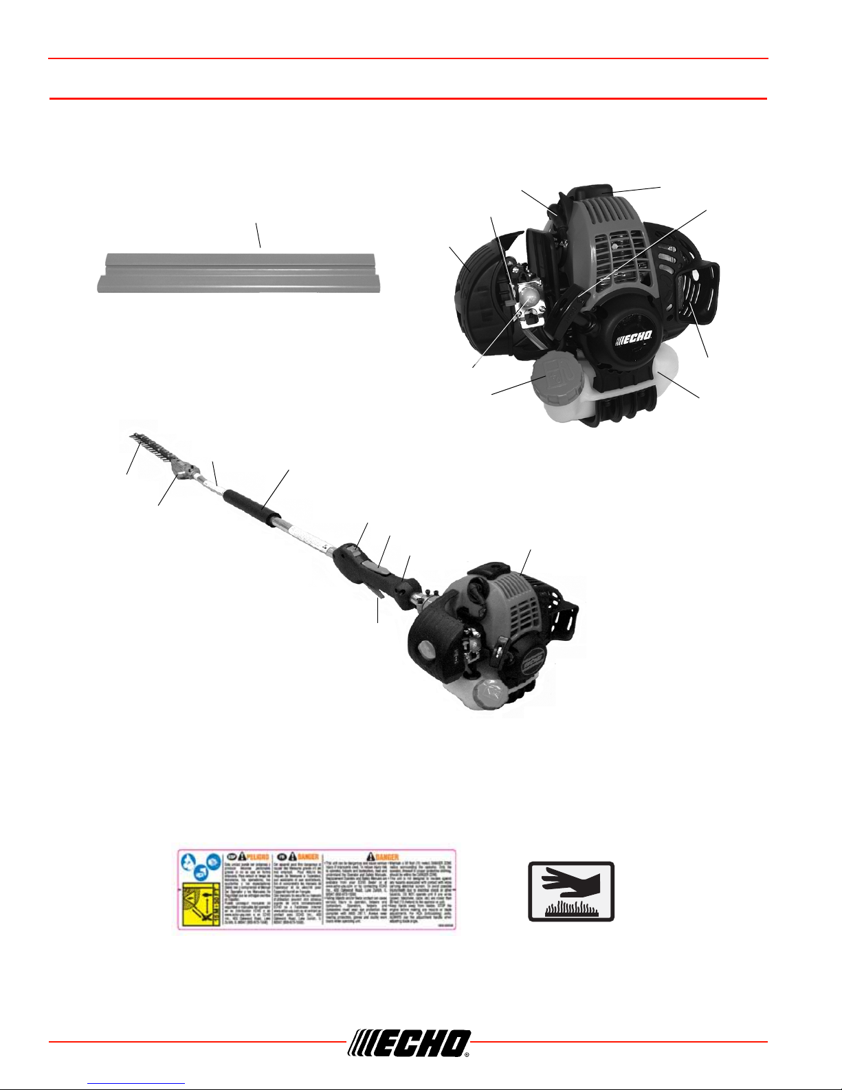
Description....................................................................................................................................... 10
Contents .......................................................................................................................................... 12
Assembly ......................................................................................................................................... 13
Drive Shaft/Power Head ............................................................................................................ 13
Throttle Linkage and Ignition Leads........................................................................................... 13
Gear Housing Assembly / Drive Shaft ...................................................................................... 14
Operation ......................................................................................................................................... 15
Fuel............................................................................................................................................ 15
Starting Cold Engine.................................................................................................................. 17
Starting Warm Engine................................................................................................................ 18
Stopping Engine......................................................................................................................... 19
Hedge Trimming ........................................................................................................................ 19
Maintenance .................................................................................................................................... 20
Skill Levels................................................................................................................................. 20
Maintenance Intervals................................................................................................................ 20
Air Filter...................................................................................................................................... 21
Fuel Filter................................................................................................................................... 21
Cooling System.......................................................................................................................... 22
Exhaust System......................................................................................................................... 23
Carburetor Adjustment............................................................................................................... 24
Lubrication ................................................................................................................................. 25
Blades........................................................................................................................................ 27
Troubleshooting ............................................................................................................................... 29
Storage ............................................................................................................................................ 30
Long Term Storage (Over 30 Days)........................................................................................... 30
Specifications................................................................................................................................... 31
Warranty Statements ....................................................................................................................... 32
Notes ............................................................................................................................................... 34

SHC-266 INTRODUCTION
X7502026702 3
© 4/2013 ECHO Inc.
INTRODUCTION
Welcome to the ECHO family. This ECHO product was designed and manufactured to provide long life and
on-the-job dependability. Read and understand this manual and the SAFETY MANUAL. You will find both
easy to use and full of helpful operating tips and SAFETY messages.
The Operator’s Manual
Keep it in a safe place for future reference. Contains specifications and information for safety, operation,
maintenance, storage and assembly specific to this product.
The Safety Manual
Keep it in a safe place for future reference. Explains possible hazards and the measures you should take to
insure safe operation.
SERVICING INFORMATION
Parts/Serial Number
Genuine ECHO Parts and ECHO REPOWER™ Parts and
Assemblies for your ECHO products are available only from an
Authorized ECHO Dealer. When you do need to buy parts always
have the Model Number and Serial Number of the unit with you. You
can find these numbers on the engine housing. For future
reference, write them in the space provided below.
Model No. _________________ SN. ___________________
Service
Service of this product during the warranty period must be performed by an Authorized ECHO Service
Dealer. For the name and address of the Authorized ECHO Service Dealer nearest you, ask your retailer or
call: 1-800-432-ECHO (3246). Dealer information is also available on our Web Site. When presenting your
unit for Warranty service/repairs, proof of purchase is required.
Echo Consumer Product Support
If you require assistance or have questions concerning the application, operation or maintenance of this
product you may call the ECHO Consumer Product Support Department at 1-800-673-1558 from 8:30 am to
4:30 pm (Central Standard Time) Monday through Friday. Before calling, please know the model and serial
number of your unit.
Warranty Registration
To ensure trouble free warranty coverage it is important that you register your ECHO equipment on-line at
www.echo-usa.com or by filling out the warranty registration card supplied with your unit. Registering your
product confirms your warranty coverage and provides a direct link between you and ECHO if we find it
necessary to contact you.

4X7502026702
© 4/2013 ECHO Inc.
SAFETY SHC-266
Additional or Replacement Manuals
Replacement Operator, Safety Manuals, and Parts Catalogs are available from your ECHO dealer or at
www.echo-usa.com or by contacting ECHO Inc., 400 Oakwood Road, Lake Zurich, IL 60047
(800-673-1558). Always check the ECHO Web Site for updated information.
Safety Videos are available from your Echo dealer. A $5.00 shipping charge will be required for each video.
SAFETY
Manual Safety Symbols and Important Information
Throughout this manual and on the product itself, you will find safety alerts and helpful, informational
messages preceded by symbols or key words. The following is an explanation of those symbols and key
words and what they mean to you.
The safety alert symbol accompanied by the word “DANGER” calls attention to an act or condition
which WILL lead to serious personal injury or death if not avoided.
The safety alert symbol accompanied by the word “WARNING” calls attention to an act or condition
which CAN lead to serious personal injury or death if not avoided.
The safety alert symbol accompanied by the word “CAUTION” calls attention to an act or condition
which may lead to minor or moderate personal injury if not avoided.
The enclosed message provides information necessary for the protection of the unit.
Note: This enclosed message provides tips for use, care and maintenance of the unit.
CIRCLE AND SLASH SYMBOL
This symbol means the specific action shown is prohibited. Ignoring these prohibitions can result
in serious or fatal injury.

SHC-266 SAFETY
X7502026702 5
© 4/2013 ECHO Inc.
International Symbols
Personal Condition and Safety Equipment
Users of this product risk injury to themselves and others if the unit is used improperly and/or safety
precautions are not followed. Proper clothing and safety gear must be worn when operating unit.
Physical Condition
Your judgment and physical dexterity may not be good:
• if you are tired or sick,
• if you are taking medication,
• if you have taken alcohol or drugs.
Operate unit only if you are physically and mentally well.
Eye Protection
Eye protection that meets ANSI Z87.1 or CE requirements must be worn whenever you operate the unit.
Hand Protection
Wear no-slip, heavy duty work gloves to improve your grip on the handles. Gloves also reduce the
transmission of machine vibration to your hands.
Breathing Protection
Wear a facemask to protect against dust.
Symbol Description Symbol Description Symbol Description Symbol Description
Read and
understand
owners manual.
Fuel and oil
mixture
Carburetor
Adjustment - Low
speed mixture
Carburetor
Adjustment - High
speed mixture
Wear eye, ear
and head
protection
Finger severing Safety/Alert
Carburetor
Adjustment - Idle
speed
Emergency Stop Hot Surface
Avoid all power
lines. This unit is
not insulated
against electrical
current.
Do not operate
closer than 15 M
(50 ft.) from
electrical hazard.
Wear hand and
foot protection.
Use two handed
DO NOT smoke
near fuel
Plan retreat path
from falling
objects
Primer Bulb
Choke Control
“Cold Start”
Position (Choke
Closed)
Ignition
ON / OFF
DO NOT allow
flames or sparks
near fuel
Wear slip
resistant footwear
Choke Control
“Run” Position
(Choke Open)
Do not operate
closer than 15 M
(50 ft.) from
electricalhazards.
Keep bystanders
at least
4.5 meters (15 ft.)
away.
Chain Lubrication.

6X7502026702
© 4/2013 ECHO Inc.
SAFETY SHC-266
Hearing Protection
ECHO recommends wearing hearing protection whenever unit is used.
Proper Clothing
Wear snug fitting, durable clothing;
• Pants should have long legs, shirts with long sleeves.
• DO NOT WEAR SHORTS,
• DO NOT WEAR TIES, SCARVES, JEWELRY, or clothing with loose or hanging items that could become
entangled in moving parts or surrounding growth.
Wear sturdy work shoes with nonskid soles;
• DO NOT WEAR OPEN TOED SHOES,
• DO NOT OPERATE UNIT BAREFOOTED.
Wear no-slip, heavy duty work gloves.
Keep long hair away from engine and air intake. Retain hair with cap or net.
Hot Humid Weather
Heavy protective clothing can increase operator fatigue which may lead to heat stroke. Schedule heavy work
for early morning or late afternoon hours when temperatures are cooler.
The ignition componentsof this machine generate an electromagnetic fieldduring operation which
may interfere with some pacemakers.To reduce the risk of serious or fatal injury, persons with
pacemakers should consult with their physician and the pacemaker manufacturer before operating
this machine.In the absence of such information, ECHO does not recommend the use ofECHO
products by anyonewho has a pacemaker.
Vibration and Cold
It is believed that a condition called Raynaud’s Phenomenon,
which affects the fingers of certain individuals, may be brought
about by exposure to vibration and cold. Exposure to vibration
and cold may cause tingling and burning sensations, followed
by loss of color and numbness in the fingers. The following
precautions are strongly recommended, because the minimum
exposure, which might trigger the ailment, is unknown.
• Keep your body warm, especially the head, neck, feet, ankles,
hands, and wrists.
• Maintain good blood circulation by performing vigorous arm exercises during frequent work breaks, and
also by not smoking.
• Limit the hours of operation. Try to fill each day with jobs where operating the unit or other hand-held
power equipment is not required.
• If you experience discomfort, redness, and swelling of the fingers followed by whitening and loss of feeling,
consult your physician before further exposing yourself to cold and vibration.

SHC-266 SAFETY
X7502026702 7
© 4/2013 ECHO Inc.
Repetitive Stress Injuries
It is believed that overusing the muscles and tendons of the
fingers, hands, arms, and shoulders may cause soreness,
swelling, numbness, weakness, and extreme pain in those
areas. Certain repetitive hand activities may put you at a high
risk for developing a Repetitive Stress Injury (RSI). An extreme
RSI condition is Carpal Tunnel Syndrome (CTS), which could
occur when your wrist swells and squeezes a vital nerve that
runs through the area. Some believe that prolonged exposure to
vibration may contribute to CTS. CTS can cause severe pain for
months or even years.
To reduce the risk of RSI/CTS, do the following:
• Avoid using your wrist in a bent, extended, or twisted position. Instead try to maintain a straight wrist
position. Also, when grasping, use your whole hand, not just the thumb and index finger.
• Take periodic breaks to minimize repetition and rest your hands.
• Reduce the speed and force with which you do the repetitive movement.
• Do exercise to strengthen the hand and arm muscles.
• Immediately stop using all power equipment and consult a doctor if you feel tingling, numbness, or pain in
the fingers, hands, wrists, or arms. The sooner RSI/CTS is diagnosed, the more likely permanent nerve
and muscle damage can be prevented.
Do not operate this product indoors or in inadequately ventilated areas. Engine exhaust contains
poisonous emissions and can cause serious injury or death.
Read the Manuals
• Provide all users of this equipment with the Operator’s Manual and
Safety Manual for instructions on Safe Operation.
Clear the Work Area
• Spectators and fellow workers must be warned, and children and
animals prevented from coming nearer than 15 m (50 ft.) while the
unit is in use.
Keep a Firm Grip
• Hold the front and rear handles with thumbs and fingers encircling
the grips.
Keep a Solid Stance
• Maintain footing and balance at all times. Do not stand on slippery, uneven or unstable surfaces. Do not
work in odd positions or on ladders. Do not over reach.

8X7502026702
© 4/2013 ECHO Inc.
SAFETY SHC-266
Avoid Hot Surfaces
• Keep exhaust area clear of flammable debris. Avoid contact
during and immediately after operation.
Never perform blade maintenance procedures while engine is running.
Equipment
Use only ECHO approved attachments. Serious injury may result from the use of a non-approved
attachment combination. ECHO, INC. will not be responsible for the failure of cutting devices,
attachments or accessories which have not been tested and approved by ECHO. Read and comply
with all safety instructions listed in this manual and safety manual.
• Check unit for loose/missing nuts, bolts, and screws. Tighten and/or replace as needed.
• Check that the cutting attachment is firmly attached and in safe operating condition. Dull, loose or
damaged blades should not be used.
Moving parts can amputate fingers or cause severe injuries. Keep hands, clothing and loose objects
away from all openings.
•ALWAYS stop engine, disconnect spark plug, and make sure all moving parts have come to a
complete stop before removing obstructions, clearing debris, or servicing unit.
•DO NOT start or operate unit unless all guards and protective covers are properly assembled to
unit.
•NEVER reach into any opening while the engine is running. Moving parts may not be visible
through openings.
Check fuel system for leaks due to fuel tank damage, especially if the unit is dropped. If damage or
leaks are found, do not use unit, otherwise serious personal injury or property damage may occur.
Have unit repaired by an authorized servicing dealer before using.

SHC-266 EMISSION CONTROL (EXHAUST & EVAPORATIVE)
X7502026702 9
© 4/2013 ECHO Inc.
EMISSION CONTROL (EXHAUST & EVAPORATIVE)
EPA 2010 and Later and/or C.A.R.B. TIER III
The emission control system for the engine is EM (engine modification)
and, if the second to last character of the Engine Family on the Emission
Control Information label (sample below) is “C”, “K”, or “T”, the emission
control system is EM and TWC (3-way catalyst). The fuel tank/fuel line
emission control system is EVAP (evaporative emissions). Evaporative
emissions for California models are only applicable to fuel tanks.
An Emission Control Label is located on the engine. (This is an
EXAMPLE ONLY, information on label varies by engine FAMILY).
Product Emission Durability (Emission Compliance Period)
The 50 or 300 hour emission compliance period is the time span
selected by the manufacturer certifying the engine emissions output
meets applicable emissions regulations, provided that approved
maintenance procedures are followed as listed in the Maintenance Section of this manual.

10 X7502026702
© 4/2013 ECHO Inc.
DESCRIPTION SHC-266
DESCRIPTION
Locate the safety decal(s) on your unit. Make sure the decal(s) is legible and that you understand and follow
the instructions on it. If a decal cannot be read, a new one can be ordered from your ECHO dealer. See
PARTS ORDERING instructions for specific information.
9
1
2
3
4
5
6
7
8
10
11 12
14
15
16
17
18
19
13
Hot Label
Shaft Label

SHC-266 DESCRIPTION
X7502026702 11
© 4/2013 ECHO Inc.
1. POWER HEAD - Includes the Engine, Clutch, Fuel System, Ignition System and Recoil Starter.
2. THROTTLE HANDLE - FOR RIGHT HAND - Contains Stop Switch, Throttle Lockout, and Throttle
Trigger.
3. THROTTLE TRIGGER LOCKOUT - This lever must be held during starting. Operation of the throttle
trigger is prevented unless throttle trigger lockout lever is engaged.
4. STOP SWITCH - “SLIDE SWITCH” mounted on top of the Throttle Trigger Housing. Move switch
FORWARD to RUN, BACK to STOP.
5. SUPPORT HANDLE - FOR LEFT HAND - Cushioned grip for Left Hand.
6. DRIVE SHAFT ASSEMBLY - Includes the flex drive shaft, rear handle assembly, harness ring,
cushioned front shaft grip, and safety decals.
7. BLADES - Double reciprocating blades mounted to a blade support bar. Double sided blades, are
capable of cutting on either side.
8. GEAR HOUSING ASSEMBLY - Gear housing assembly fixed straight extension.
9. THROTTLE TRIGGER - Spring loaded to return to idle when released. During acceleration, depress
gradually for best operating technique.
10. BLADE COVER - Used to cover blade during transport and storage. Remove blade cover before using
unit.
11. SPARK PLUG - Provides spark to ignite fuel mixture.
12. TOP GUARD - Protects arm from the hot engine.
13. SPARK ARRESTOR MUFFLER OR SPARK ARRESTOR MUFFLER WITH CATALYST - The muffler or
catalytic muffler controls exhaust noise and emission. The spark arrestor screen prevents hot, glowing
particles of carbon from leaving the muffler. Keep exhaust area clear of flammable debris.
14. FUEL TANK - Contains fuel and fuel filter.
15. RECOIL STARTER HANDLE - Pull handle slowly until starter engages, then quickly and firmly. When
engine starts, return handle slowly. DO NOT let handle snap back or damage to unit will occur.
16. FUEL TANK CAP - Covers and seals fuel tank opening.
17. PURGE BULB - Pumping purge bulb before starting engine draws fresh fuel from the fuel tank, purging
air from the carburetor. Pump purge bulb until fuel is visible and flows freely in the clear fuel tank return
line. Pump purge bulb an additional 4 or 5 times.
18. AIR CLEANER - Contains replaceable filter element.
19. CHOKE CONTROL - Located on the air cleaner housing. Move choke lever to Cold Start ( ) to close
choke for cold start. Move choke lever to “Run” ( ) position to open choke.

12 X7502026702
© 4/2013 ECHO Inc.
CONTENTS SHC-266
CONTENTS
After opening the carton, check for damage. Immediately notify your retailer or ECHO Dealer of damaged or
missing parts. Use the contents list to check for missing parts.
____ 1 - Power Head
____ 1 - Gear Case Assembly
____ 1 - Drive Shaft Assembly
____ 1 - Operator's Manual
____ 1 - Emission Control Warranty Statement
____ 1 - Safety Manual
____ 1 - Warranty Registration Card
____ 1 - Blade Cover
____ Assembly Tools (s)

SHC-266 ASSEMBLY
X7502026702 13
© 4/2013 ECHO Inc.
ASSEMBLY
Drive Shaft/Power Head
1. Stand power head upright on a level surface.
2. Loosen the two (2) drive shaft clamp bolts (B) at engine
drive shaft clamp, and remove center drive shaft location
bolt (A).
3. Remove dust cap and carefully fit drive shaft assembly to
engine making sure that inner drive shaft engages into
clutch mount.
4. Turn drive shaft housing until locating hole lines up with
location hole in clamp and install center drive shaft location
bolt (A).
Note: Gear Housing must be aligned properly with engine.
Aligning center locating hole in driveshaft housing with center drive shaft bolt (A) provides correct
alignment.
5. Tighten two (2) drive shaft clamp bolts (B) securely.
6. Route throttle linkage and ignition lead assembly along shaft
and clip as shown.
Throttle Linkage and Ignition Leads
1. Close choke and remove air filter cover.
2. Place throttle linkage (C) through adjustment fixture (D) and
install wire end into large carburetor throttle swivel hole (E).
Check throttle for freedom of movement and that wide open
throttle / low idle extremes are adjusted properly. The
throttle linkage must be adjusted by moving the adjustment
fixture (D). Consult with your Echo Dealer for correct
adjustment procedure.
Parts Required: Power Head, Drive Shaft Assembly
A
B
A
B
C
D
E

14 X7502026702
© 4/2013 ECHO Inc.
ASSEMBLY SHC-266
3. Connect 2 ignition stop leads (F, G) from throttle cable
tubing to 2 ignition leads (F, G) on engine.
4. Secure ignition leads behind air filter case with clip (H).
5. Install air filter and cover.
Gear Housing Assembly / Drive Shaft
Note: Hedge Clipper Blades are very sharp. Wear gloves to
protect hands.
1. Remove locating bolt (A) and loosen clamping bolt (B).
2. Remove vinyl cap from drive shaft.
3. Slide Gear Housing Assembly onto Drive Shaft. Be certain
the Flex Drive Shaft engages the hole in Driver Gear.
Flat edge of washer (C) must be against drive shaft.
4. Align locating hole in gear housing with locator hole in drive shaft.
5. Install locating bolt (A). Tighten clamping bolt (B).
F
G
H
A
B
C

SHC-266 OPERATION
X7502026702 15
© 4/2013 ECHO Inc.
OPERATION
Moving parts can amputate fingers or cause severe injuries. Keep hands, clothing and loose objects
away from all openings. Always stop engine, disconnect spark plug, and make sure all moving parts
have come to a complete stop before removing obstructions, clearing debris, or servicing unit.
Operation of this equipment may create sparks that can start fires. This unit is equipped with a spark
arrestor to prevent discharge of hot particles from the engine. Metal cutters can can create sparks if
the cutter strikes rocks, metal, or other hard objects. Contact local fire authorities for laws or
regulations regarding fire prevention requirements.
Fuel
Alternative fuels, such as E-15 (15% ethanol), E-85 (85% ethanol) or any fuels not meeting ECHO
requirements are NOT approved for use in ECHO 2-stroke gasoline engines. Use of alternative fuels
may cause performance problems, loss of power, overheating, fuel vapor lock, and unintended
machine operation, including, but not limited to, improper clutch engagement. Alternative fuels may
also cause premature deterioration of fuel lines, gaskets, carburetors and other engine components.
Fuel Requirements
Gasoline - Use 89 Octane [R+M/2] (mid grade or higher) gasoline known to be good quality. Gasoline may
contain up to 10% Ethanol (grain alcohol) or 15% MTBE (methyl tertiary-butyl ether). Gasoline containing
methanol (wood alcohol) is NOT approved.
Two Stroke Oil - A two-stroke engine oil meeting ISO-L-EGD (ISO/CD 13738) and J.A.S.O. FD Standards
must be used. Echo brand premium Power Blend X TM Universal 2-Stroke Oil meets these standards. Engine
problems due to inadequate lubrication caused by failure to use an ISO-L-EGD (ISO/CD 13738) and
J.A.S.O. FD certified oil, such as Echo premium Power Blend X TM, will void the two-stroke engine warranty.
Echo premium Power Blend X TM Universal 2-Stroke Oil may be mixed at 50:1 ratio for application in all Echo
engines sold in the past regardless of ratio specified in those manuals.
Handling Fuel
Fuel is VERY flammable. Use extreme care when mixing, storing or handling, or serious personal
injury may result.
•Use an approved fuel container.
•DO NOT smoke near fuel.
•DO NOT allow flames or sparks near fuel.
•Fuel tanks/cans may be under pressure. Always loosen fuel caps slowly allowing pressure to
equalize.

16 X7502026702
© 4/2013 ECHO Inc.
OPERATION SHC-266
•NEVER refuel a unit when the engine is HOT or RUNNING!
•DO NOT fill fuel tanks indoors. ALWAYS fill fuel tanks outdoors over bare ground.
•DO NOT overfill fuel tank. Wipe up spills immediately.
•Securely tighten fuel tank cap and close fuel container after refueling.
•Inspect for fuel leakage. If fuel leakage is found, do not start or operate unit until leakage is
repaired.
•Move at least 3m (10 ft.) from refueling location before starting the engine.
Mixing Instructions
1. Fill an approved fuel container with half of the required
amount of gasoline.
2. Add the proper amount of 2-stroke oil to gasoline.
3. Close container and shake to mix oil with gasoline.
4. Add remaining gasoline, close fuel container, and remix.
Spilled fuel is a leading cause of hydrocarbon emissions. Some
states may require the use of automatic fuel shut-off containers
to reduce fuel spillage.
After use
• DO NOT store a unit with fuel in its tank. Leaks can occur. Return unused fuel to an approved fuel storage
container.
Storage - Fuel storage laws vary by locality. Contact your local government for the laws affecting your area.
As a precaution, store fuel in an approved, airtight container. Store in a well-ventilated, unoccupied building,
away from sparks and flames.
Stored fuel ages. Do not mix more fuel than you expect to use in thirty (30) days, ninety (90) days when a
fuel stabilizer is added.
Stored two-stroke fuel may separate. ALWAYS shake fuel container thoroughly before each use.

SHC-266 OPERATION
X7502026702 17
© 4/2013 ECHO Inc.
Starting Cold Engine
Hedge Clipper blades are very sharp. Touching them may lead to severe personal injury. Avoid
touching blades whenever possible, and always wear gloves to protect hands.
Note: The blade cover is used for transportation and storage. Remove blade cover before using the unit.
The attachment will operate immediately when the engine starts, and could result in possible
serious injury.Keep movable parts of the attachment away from objects that could become
entangled or thrown, and surfaces that could cause loss of control.
1. Stop Switch
Move stop switch (A) away from the STOP position.
2. Choke
Move choke (B) to Cold Start ( ) (closed) position.
3. Purge Bulb
Pump purge bulb (C) until fuel is visible and flows freely in the
clear fuel tank return line. Pump bulb an additional 4 or 5
times.
4. Recoil Starter
Lay the unit on a flat area and keep movable attachment parts
clear of all obstacles. Firmly grasp throttle handle and throttle
trigger lockout with left hand and fully depress throttle trigger
to wide open position. Rapidly pull recoil starter handle/rope
(D) until engine fires (or maximum five [5] pulls).
5. Choke
After engine fires (or 5 pulls), move choke (B) to the Run
( ) (open) position. Firmly grasp throttle handle and throttle
trigger lockout with left hand and fully depress throttle trigger
to wide open position. Pull starter handle/rope until engine
starts and runs. Release throttle trigger and allow unit to warm up at idle for several minutes.
Note: If engine does not start with choke in “Run” position after 5 pulls, repeat instructions 2 - 5.
A
B
C
D
D

18 X7502026702
© 4/2013 ECHO Inc.
OPERATION SHC-266
The blades must not move at idle, otherwise serious personal injury may result. Periodic carburetor
adjustment may be necessary to assure blades do not move at idle. If blades move, readjust
carburetor according to “Carburetor Adjustment” instructions in this manual or see your ECHO
Dealer.
6. Throttle Trigger
After engine warm-up, grip the rear handle and front handle. Depress the throttle trigger lockout, and
gradually depress throttle trigger to increase engine RPM to operating speed.
Starting Warm Engine
The starting procedure is the same as Cold Start except DO
NOT close the choke, and do not depress throttle trigger to wide
open position.
The blades must not move at idle, otherwise serious
personal injury may result. Periodic carburetor adjustment
may be necessary to assure blades do not move at idle. If
blades move, readjust carburetor according to “Carburetor
Adjustment” instructions in this manual or see your ECHO Dealer.
1. Stop Switch
Move stop switch (A) away from the STOP position.
2. Purge Bulb
Pump purge bulb (C) until fuel is visible and flows freely in the
clear fuel tank return line. Pump bulb an additional 4 or 5
times.
3. Recoil Starter
Lay the unit on a flat area and keep movable attachment parts
clear of all obstacles. Firmly grip throttle handle and throttle
trigger lockout with left hand. Rapidly pull recoil starter
handle/rope (D) until engine fires.
Note: If engine does not start after 5 pulls, use Cold Start
Procedure.
A
B
C
D
D

SHC-266 OPERATION
X7502026702 19
© 4/2013 ECHO Inc.
Stopping Engine
1. Throttle
Release throttle and allow engine to return to idle before
shutting off engine.
2. Stop Switch
Move stop switch (A) to STOP position.
If engine does not stop when stop switch is moved to STOP position, close choke - COLD START
position - to stall engine. Have your ECHO dealer repair stop switch before using trimmer again.
Hedge Trimming
Engine exhaust IS HOT, and contains Carbon Monoxide (CO), a poison gas. Breathing CO can cause
unconsciousness, serious injury, or death. Exhaust can cause serious burns. ALWAYS position
unit so that exhaust is directed away from your face and body.
Hedge Clipper blades are very sharp. Touching them may
lead to severe personal injury. Avoid touching blades
whenever possible, and always wear gloves to protect
hands.
1. Always grip throttle handle with right hand and support
handle with left hand while trimming.
2. Hold trimmer firmly and squeeze throttle trigger to
accelerate engine.
3. Tilt trimmer so cutting teeth are angled slightly toward the
hedge or shrub and proceed to cut.
Never remove hands from unit when blades are moving.
The engine continues running even when the blades have stopped due to an obstruction. If this
occurs, stop the engine, disconnect ignition cable and remove the obstruction
A

20 X7502026702
© 4/2013 ECHO Inc.
MAINTENANCE SHC-266
MAINTENANCE
Moving parts can amputate fingers or cause severe injuries. Keep hands, clothing and loose objects
away from all openings. Always stop engine, disconnect spark plug, and make sure all moving parts
have come to a complete stop before removing obstructions, clearing debris, or servicing unit.
Allow unit to cool before performing service. Wear gloves to protect hands from sharp edges and
hot surfaces.
Your ECHO unit is designed to provide many hours of trouble free service. Regular scheduled maintenance
will help your unit achieve that goal. If you are unsure or are not equipped with the necessary tools, you may
want to take your unit to an ECHO Service Dealer for maintenance. To help you decide whether you want to
DO-IT-YOURSELF or have the ECHO Dealer do it, each maintenance task has been graded. If the task is
not listed, see your ECHO Dealer for repairs.
Skill Levels
Level 1 = Easy to do. Common tools may be required.
Level 2 = Moderate difficulty. Some specialized tools may be required.
ECHO offers REPOWERTM Maintenance Kits and Parts to make your maintenance job easier.
Maintenance Intervals
MAINTENANCE PROCEDURE LETTER CODES: I = INSPECT, R = REPLACE, C = CLEAN
IMPORTANT NOTE - Time intervals shown are maximum. Actual use and your experience will determine the
frequency of required maintenance.
MAINTENANCE PROCEDURE NOTES:
1. Apply POWER BLENDXTM grease every 25 hours of use.
2. Inspect blade, and clean and sharpen as needed. Lubricate blades periodically during use
COMPONENT/SYSTEM MAINTENANCE
PROCEDURE
REQ’D
SKILL
LEVEL
DAILY
OR
BEFORE
USE
EVERY
REFUEL
3
MONTHS YEARLY
Air Filter Inspect/Clean 1I/C* R *
Choke Shutter Inspect/Clean 1 I / C
Fuel Filter Inspect/Replace 1I*I / R *
Fuel Cap Gasket Inspect/Replace 1I*R *
Fuel System Inspect/Replace 1I(3)*I (3) *
Spark Plug Inspect/Clean/Replace 1 I / C / R *
Cooling System Inspect/Clean 2 I / C
Muffler Spark Arrestor Inspect/Clean/Replace 2 I / C / R *
Cylinder Exhaust Port Inspect/Clean/Decarbon 2I/C
Drive Shaft (flex cable
models)
Grease 2I(1)
Gear Housing Grease 2I(1)
Blades Inspect/Clean 1 I / C (2)
Recoil Starter Rope Inspect/Clean 1I/C*
Screws/Nuts/Bolts Inspect/Tighten/Replace 1I*
Other manuals for SHC-266
1
Table of contents
Other Echo Lawn And Garden Equipment manuals

Echo
Echo Pro Attachment Series User manual

Echo
Echo PAS-260 PRO - 01-07 User manual

Echo
Echo WV160 User manual

Echo
Echo HC-150 User manual

Echo
Echo 99944200418 User manual

Echo
Echo 99944200595 User manual

Echo
Echo BRUSHCUTTER User guide

Echo
Echo SHC-2401 User manual

Echo
Echo SHC-2100 User manual

Echo
Echo HC-181 User manual

Echo
Echo SHC-266 User manual

Echo
Echo EA-410 User manual

Echo
Echo hcas-235es User manual

Echo
Echo POWER PRUNER DPPT-2600H User manual

Echo
Echo PAS-260 PRO - 08-00 User manual

Echo
Echo SHC-251 User manual

Echo
Echo BRD-280 User manual

Echo
Echo SHC-210 User manual

Echo
Echo HC-233 User manual

Echo
Echo PAS-260 PRO - 12-06 User manual