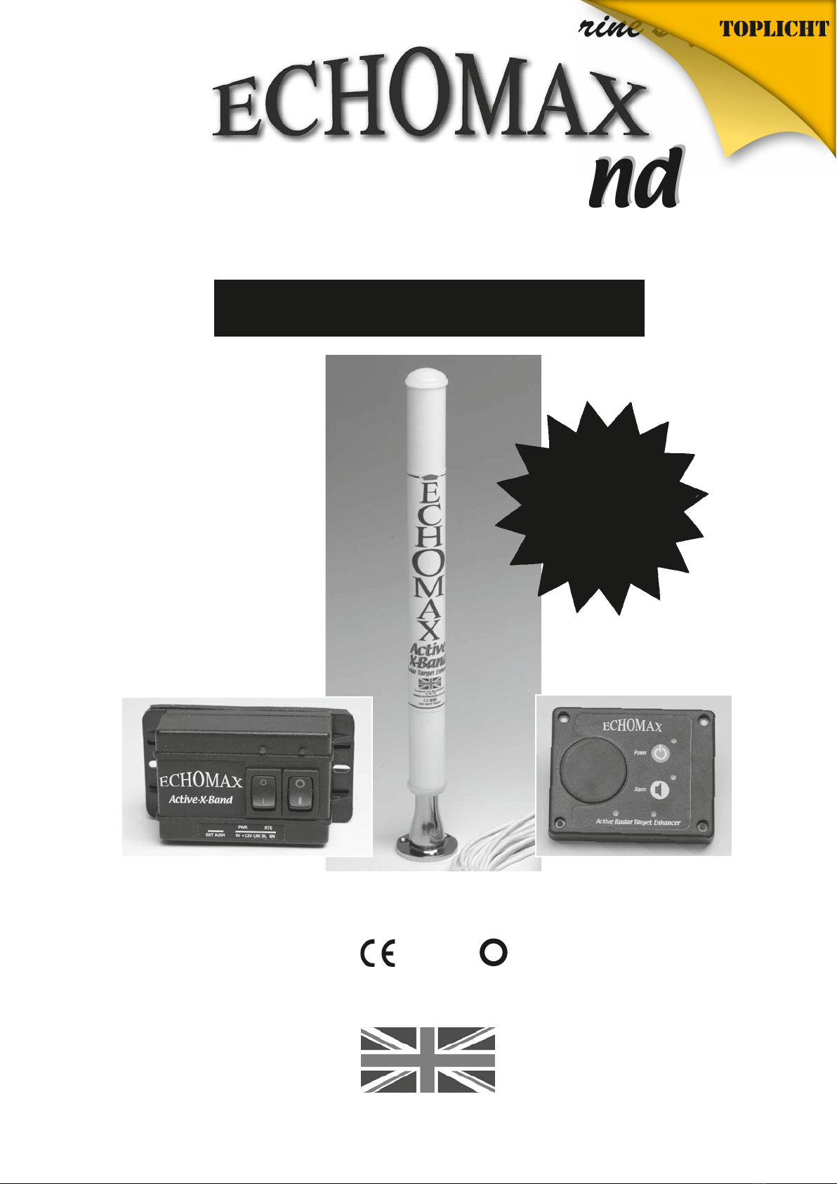
Radar Target Enhancer
Radar Target Enhancer
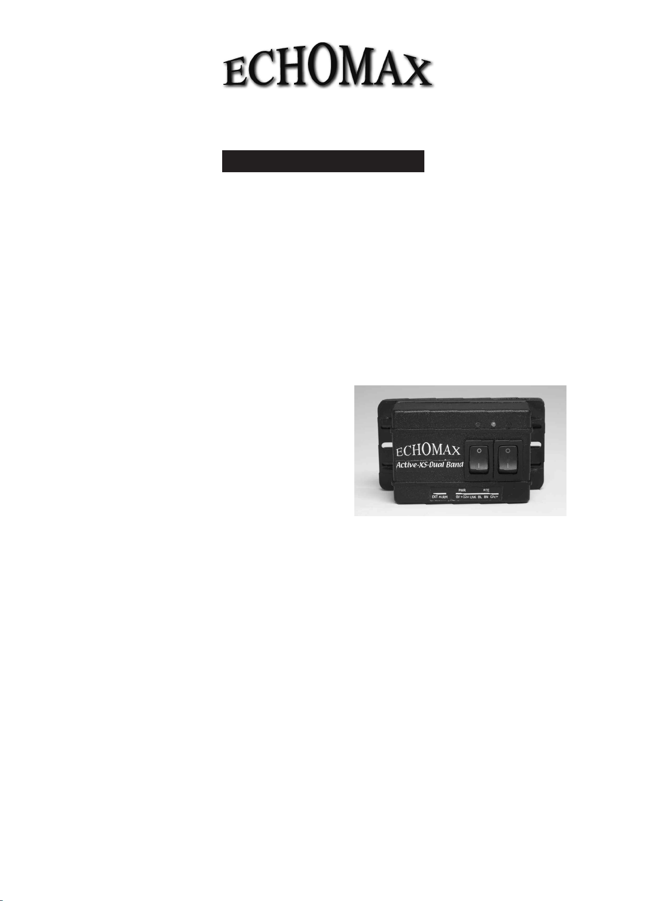
Active-XS-DualBand
Active-XS-DualBand
GENERAL INTRODUCTION
The Echomax Active-XS-Dual Band Radar Target Enhancer (RTE) is designed to respond to interrogating both X (9.3 - 9.5
GHz) and S band radar (2.9 - 3.1 GHz) by receiving a transmitted pulse, amplifying and re-transmitting the pulse back to the
radar at the same frequency with minimum delay, thereby improving the radar detection range and visibility of small
targets. It will not enhance significantly vessels with large radar cross section. The Active-XS-Dual Band Radar Target
Enhancer is suitable for all vessels up to 150 gross tonnage.
SOLAS V Regulation 19 2.1.7 states (Radar reflector) - All ships irrespective of size shall have, if less than 150 gross
tonnage and if practicable, a radar reflector, or other means to enable detection by ships navigating by radar at both
9 GHz (X Band) and 3 GHz. (S Band). The Active-XS-Dual Band Radar Target Enhancer will typically enhance the
RCS (radar cross section) of vessels up to 25M in length. For small craft/rigid inflatables improvements will start to
be seen at around 1-2 miles extending to 8-10 miles or more depending on prevailing conditions.
The response of the RTE will vary according to range, RTE and radar height above sea level, radar power and condition.
Poor weather, sea state and precipitation will greatly reduce the response.
IMPORTANT
The fitting of the Echomax Active-XS-Dual Band RTE does
not exclude you from exercising safe navigational judgement
for your vessel under the International Regulations for the
Prevention of Collisions at Sea and to keep a proper look out
at all times.
LICENSING REQUIREMENTS
Many countries and administrations require a ships radio
license or modification of your existing ships radio licence
before Active-XS can be used for maritime use. Contact your
local administration for details.
ECHOMAX ACTIVE-XS COMPONENTS,
CONSTRUCTION, use and installation
If you are not able to safely install the unit yourself you are
advised to seek the services of a competent person or
company to install the RTE.
COMPONENTS
Echomax Active-XS mast head radome fitted with
25 meters of 3 core cable
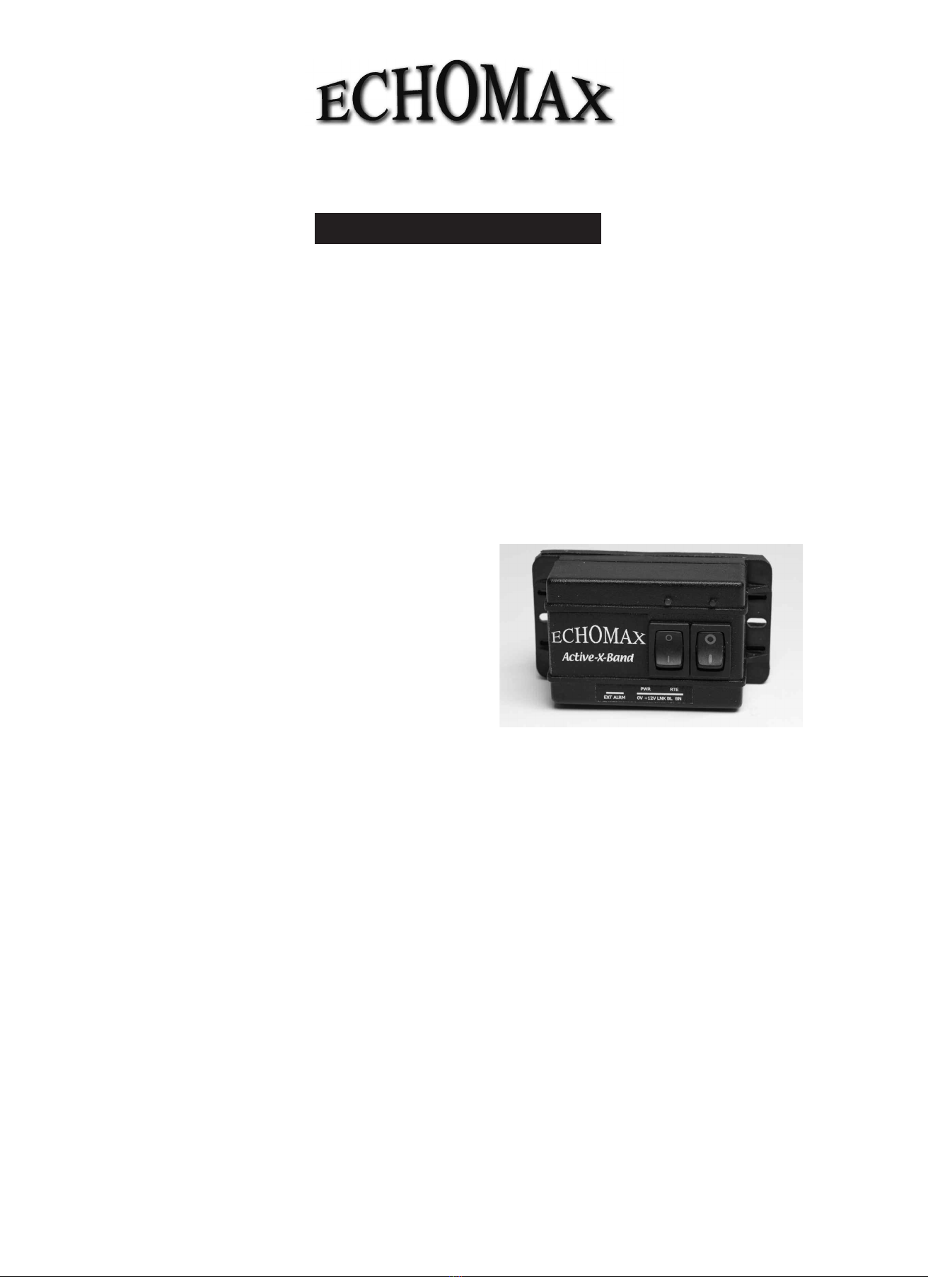
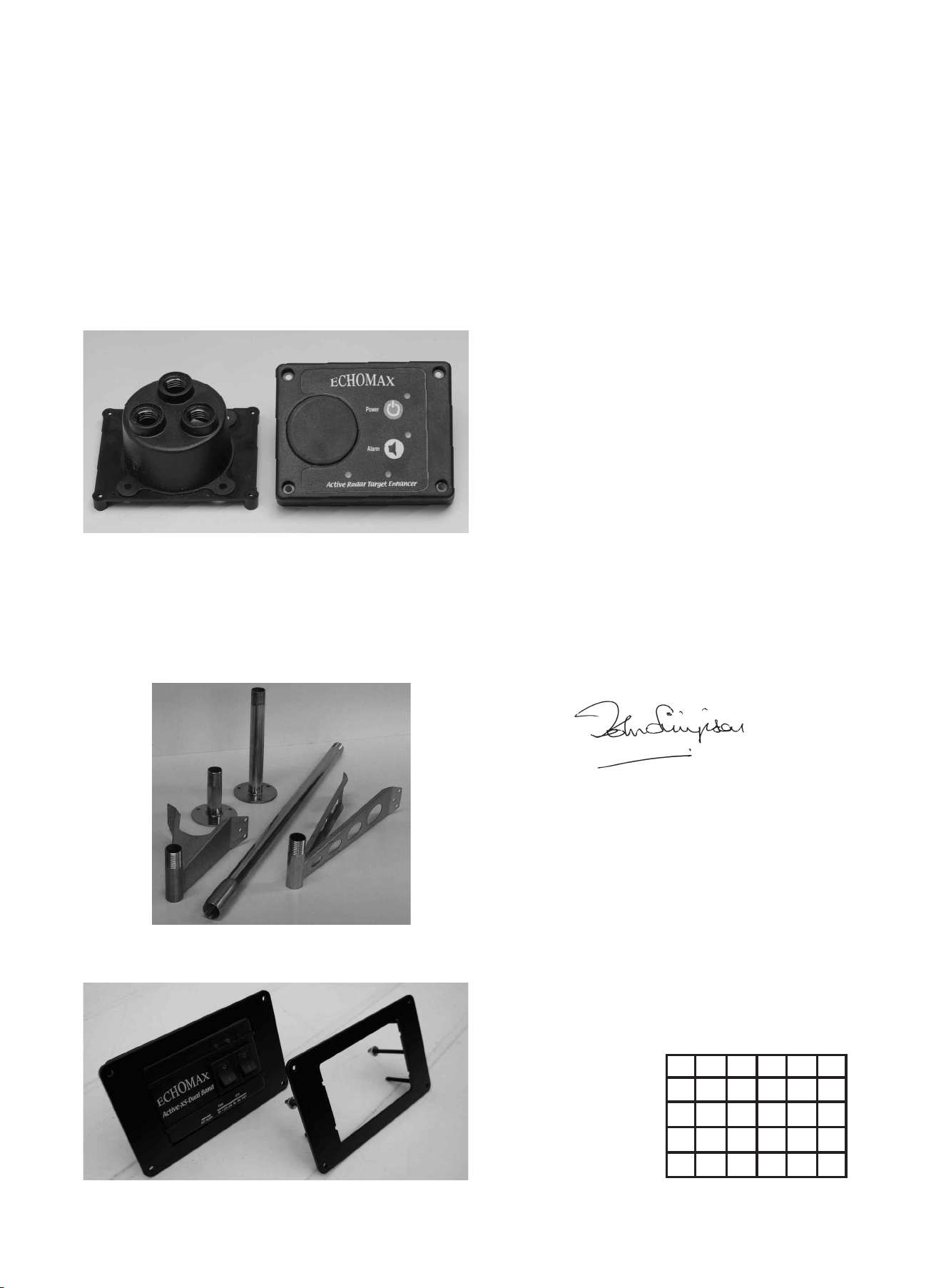
Control Box
Operation Manual
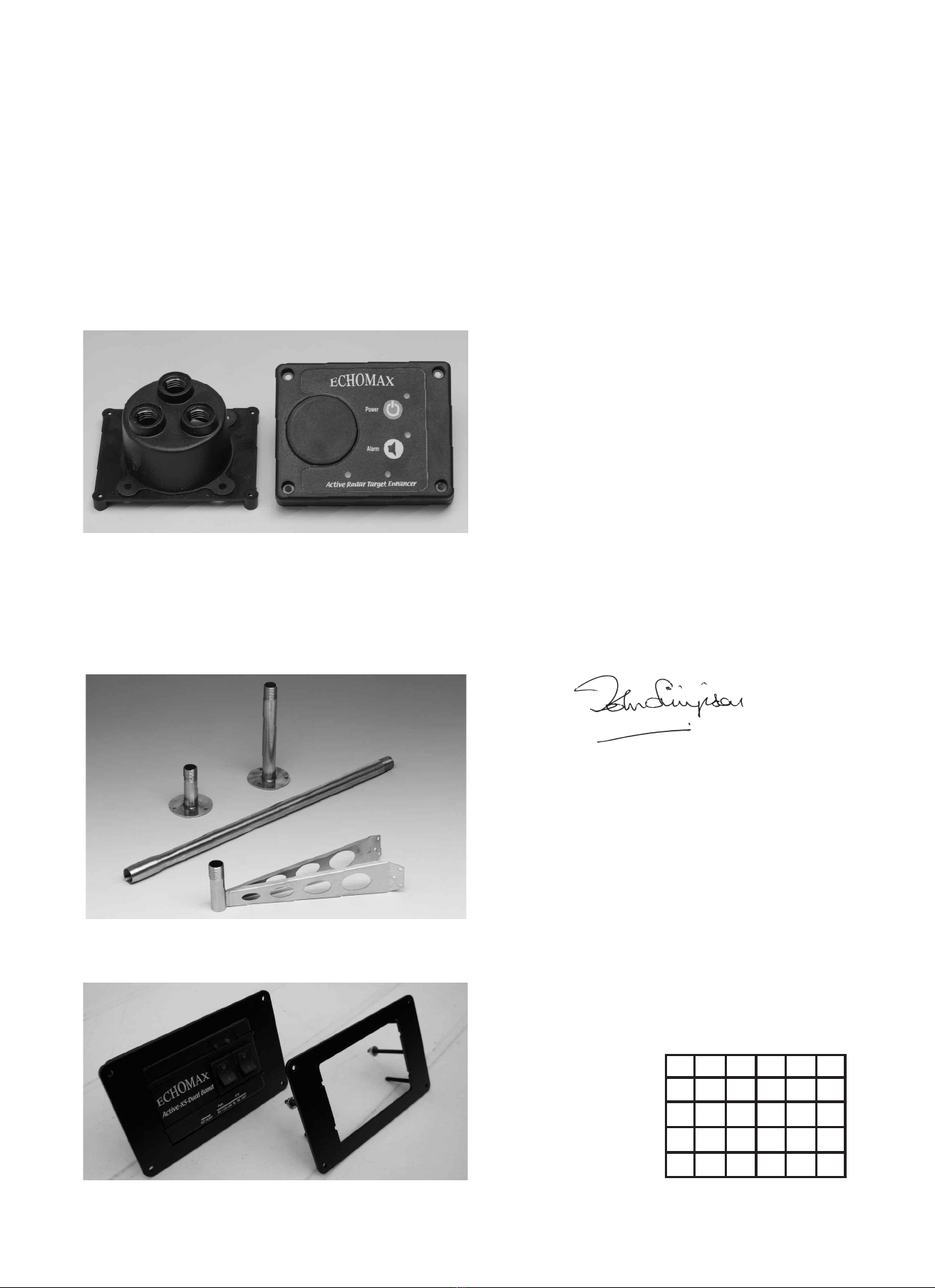
RADOME FITTING
The antenna has provisions in the base for a 1 inch -14 NF
female thread mast fitting or deck mount bracket. Plastic
mounts should not be used. To ensure a permanent fixing
‘LOCTITE’ or PTFE or plumbers tape should be used and the
RTE must be screwed down tightly. Care must be taken to
ensure that as the RTE is tightened on the base the cable is
allowed to turn freely.
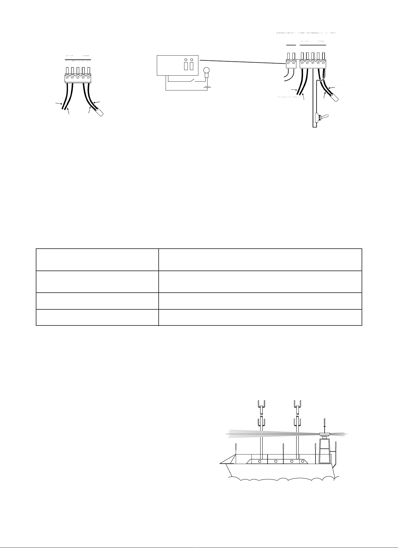
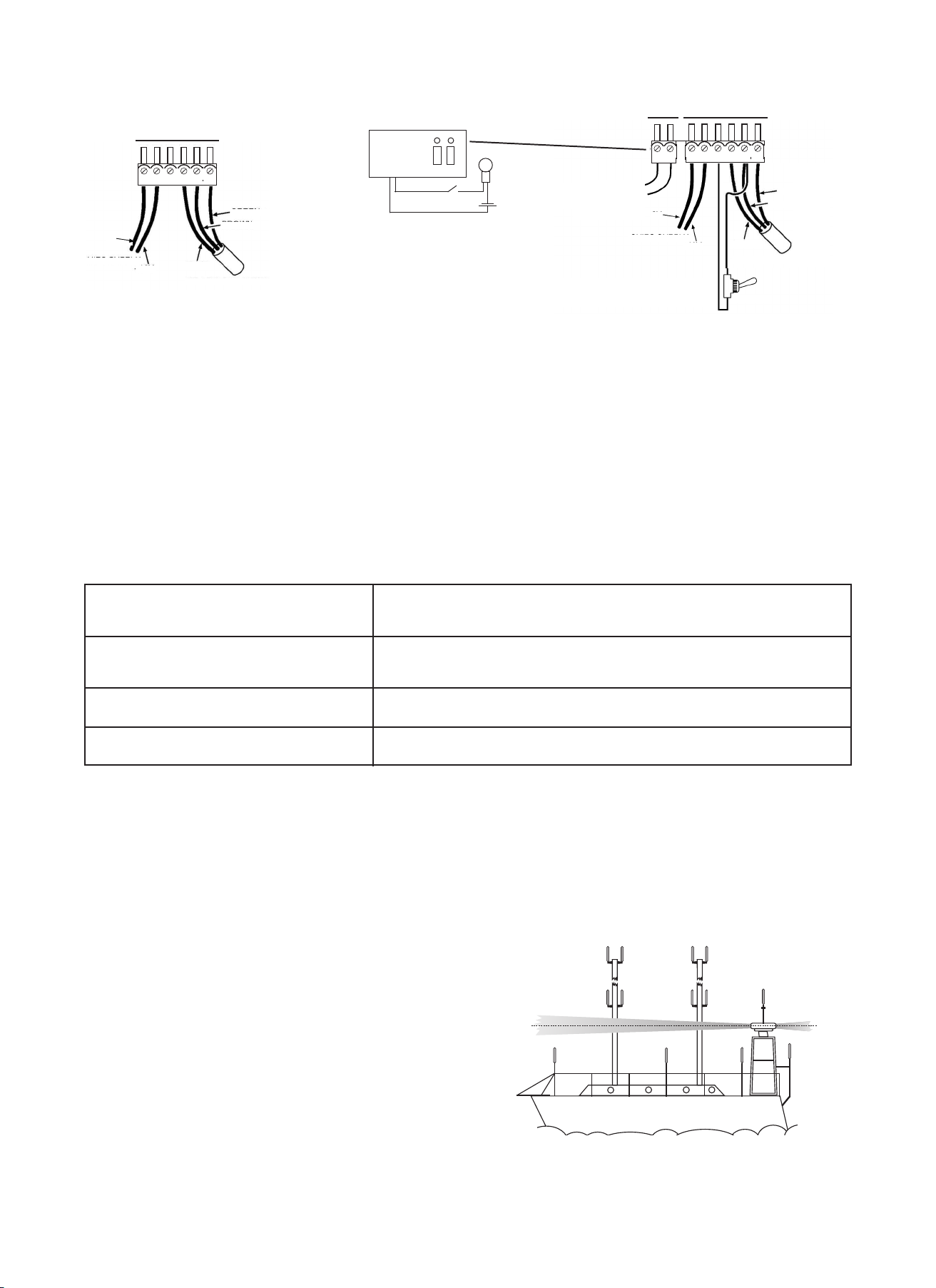
For mast fitting the radome should be fitted vertically at
masthead or as illustrated on the following page. The transmit
antennas are positioned 70mm from the base of the radome
and need a clear 360 degree azimuth. When fitted at mast head
keep as far away as possible from other fittings to reduce
shadowing using the Echomax mast bracket. The radome will
not interfere electrically with other mast head fittings. It should
not be fitted on a back stay or where its vision is obscured or is
close to any metal object otherwise performance could be
significantly impaired.
The radome unit must never be painted as this will seriously
impair performance. The radome must not be fitted in or close
to the vessels radar transmitting beam width of 28 degrees as
this may seriously damage the PCB. The RTE can be fitted
ECHOMAX CONTROL BOX for surface fittin
or flush mount fittin with optional flush
mount kit
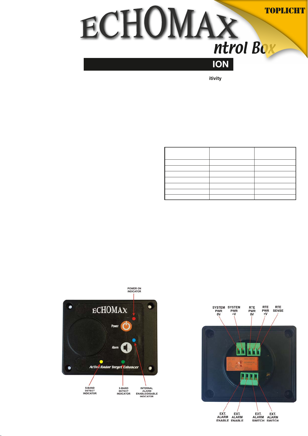
The control box must be fitted internally as it is not waterproof
and can be wired from the base or back as required. A 12v
fused or circuit breaker supply of 3-5A is required.
The control box has a quadruple alarm facility. Once the red
power switch is turned on the unit is in the quiescent mode
and will consume up to 23mA. When interrogated by an X
Band radar the green LED light will flash every 2.4 seconds. If
the flash lengthens then this indicates that more than one radar
is painting the antenna. If painted by a high speed radar which
rotates every 1.5 seconds then the LED light will flash quicker.
When painted by an S Band radar the yellow light will flash.
It should be borne in mind that vessels with S Band radar are
very large and in most cases over 3000GT and can neither
stop nor change course quickly. Turning on the green switch
will mobilize the internal buzzer, which is set to actuate for
approximately half a second intervals. The control box also
has facilities for a 8A external volt free alarm. THIS IS NOT A
POWER SOURCE and must be initialised as shown in the
wiring diagram. The control box has an externally replaceable
0.5A fuse and is surge and cross polarity protected.
NB – ISOLATE POWER SUPPLY during installation, alteration
or repair of wiring.
REMOVAL OF FUSE
Gently push fuse in and turn anti-clockwise and then remove.
Failure to do this will damage the aluminium connections.
below or preferably above the radar. It is possible to shorten
or extend the cable by a further 25 meters without affecting
the performance using extension cable rated at 3A at 300V.