7
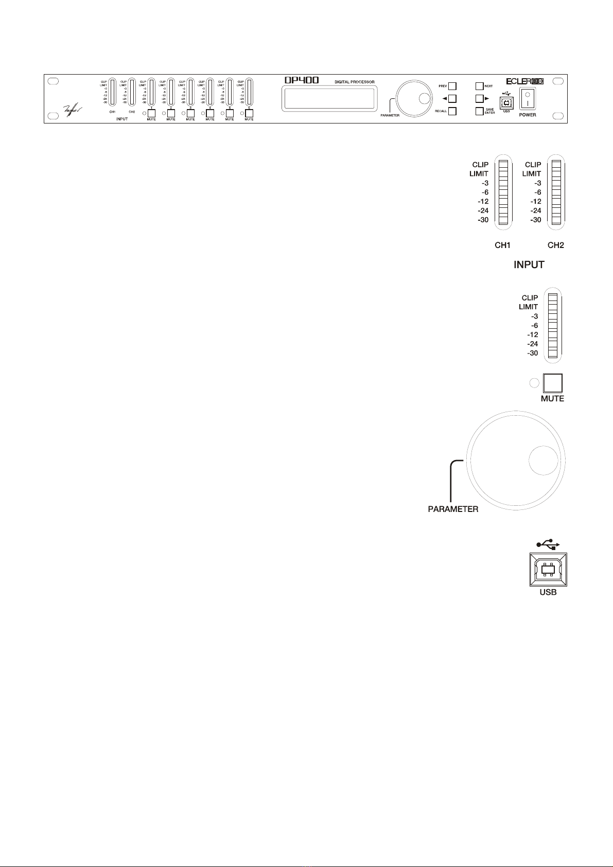
4. FRONT PANEL
Input VU-meter
The input VU-meter lets you visually monitor the input signal level, having
indications for –30dB, -24dB, -12dB, -6dB and –3dB.
Furthermore, LIMIT and CLIP indicators are provided. Apart from normal
operation for input level monitoring, digital clipping is also shown here.
If the CLIP led lights up but the LEDs below do not, this means that the
digital audio signal is clipping (DSP) and not the analogue input stage. This may
happen if inadequate EQ or excessive gain is applied to any of the outputs.
Output VU-meter
The output VU-meter lets you visually monitor the output signal level relative to a
trigger threshold adjustment. If a +4dB signal is sent to an output with a trigger threshold of
0dB, the –6dB led will light up.
MUTE Buttons
By pressing these buttons (one for each output channel) the selected channel is
muted. If the output is muted, the associated led next to the button is lit.
Rotary encoder wheel
By turning the encoder wheel clockwise or counter-clockwise,
parameters and values shown on the display can be incremented or
decremented. The encoder wheel also features a push-button function. At
each press, the parameters for the next input or output channel are
accessed cyclically. By pressing and simultaneously turning the wheel,
inputs and outputs can be accessed more quickly.
USB Connector
The system comes with a USB B-type connector that is used to communication the
DP400 up to the PC and establish a connection between the DP400 and the DP:lab2 software,
allowing you to fully manage the processor from your computer.