Eco-Aire 2400 User manual

Ussc1
Owner’s Operation and Instruction Manual
SAFETY NOTICE:
If this heater is not properly installed, a house re
may result. For your safety, follow the installation in-
structions. Contact your local building or re ofcials
about obtaining a permit, restrictions and installation
requirements in your area.
CAUTION!
Read All Instructions Carefully
Before Starting The Installation or
Operating This Heater.
Improper Installation Could Void
Your Warranty!
SAFETY TESTED TO ASTM 1509-04 & ULC S-627-00
United States Stove Company
227 Industrial Park Road
P.O. Box 151
South Pittsburg, TN 37380
SAVE THIS MANUAL FOR FUTURE REFERENCE
THIS MANUAL WILL HELP YOU TO OBTAIN EFFICIENT, DEPENDABLE SERVICE FROM THE HEATER, AND ENABLE YOU TO ORDER
REPAIR PARTS CORRECTLY. KEEP IN A SAFE PLACE FOR FUTURE REFERENCE.
WINDOW PELLET HEATER
MODEL
2400
PATENT NO.: 7,686,011
C
S
S
U
C
O
M
P
A
N
Y
U
N
I
T
E
D
S
T
A
T
E
S
S
T
O
V
E
851724C
CM
C
US
Window Pellet Unit
-

2Ussc
IMPORTANT: Read this entire manual before
installing and operating this product. Failure to do
so may result in property damage, bodily injury,
or even death. Proper installation of this heater is
crucial for safe and efcient operation. Never use
make-shift compromises during the installation.
Before installing your heater, you must perform
an initial burn in an OUTSIDE environment. Follow
the Start-Up Procedure in the Operation section
of this manual.
This heater must be installed in an exterior wall or
window to the outside.
Contact your local building ofcials to obtain
a permit and information on any additional
installation restrictions or inspection requirements
in your area.
Save these instructions.. This manual has important
operating and maintenance instructions that
you will need at a later time. Always follow the
instructions in this manual.
This heater is designed and approved for premium
hardwood pellet fuel only. Any other type of fuel
burned in this heater will void the warranty and
safety listing.
Never use gasoline, gasoline-type lantern
fuel, kerosene, charcoal lighter uid, or similar
ammable liquids to start or “freshen up” a re in
this heater. Keep all such liquids well away from
the heater while it is in use.
A working smoke detector must be installed in the
same room as this product.
Do not unplug the heater if you suspect a
malfunction. Turn the ON/OFF SWITCH to ”OFF’
and contact your dealer.
Do not operate your heater with the viewing or
combustion door open. The auger will not feed
pellets under these circumstances and a safety
concern may arise from sparks or fumes entering
the room.
Never disable or bypass the safety devices in this
unit. Doing so could result in damage to the unit
or endanger yourself or someone else.
Your heater requires periodic maintenance
and cleaning (see ”MAINTENANCE ”). Failure to
maintain your heater may lead to improper and/
or unsafe operation.
Never try to repair or replace any part of the
heater unless instructions for doing so are given
in this manual. All other work should be done by
a trained technician.
Turn the heater OFF and allow to completely cool
before performing any maintenance.
Safety Precautions
Disconnect the power cord before performing any
maintenance! NOTE: Turning the ON/OFF Switch
to ”OFF” does not disconnect all power to the
electrical components of the heater.
Ashes must be disposed in a metal container with
a tight tting lid. The closed container of ashes
should be placed on a non-combustible surface
or on the ground, well away from all combustible
materials, pending nal disposal.
The exhaust system should be checked bi- monthly
during the burning season for any build-up of
yash, soot or creosote.
HOT WHILE IN OPERATION. KEEP CHILDREN
CLOTHING AND FURNITURE AWAY. CONTACT MAY
CAUSE SKIN BURNS. Do not touch the hot surfaces
of the heater. Educate all children on the dangers
of a high-temperature heater. Young children
should be supervised when they are in the same
room as the heater.
A power surge protector is required. This unit must
be plugged into a 110 - 120V, 60 Hz grounded
electrical outlet. Do not use an adapter plug
or sever the grounding plug. Do not route the
electrical cord over the heater. Do not route the
cord in foot trafc areas or pinch the cord under
furniture.
The heater will not operate during a power
outage. If a power outage does occur, check the
heater for smoke spillage and open a window if
any smoke spills into the room.
Never block free airow through the open vents
of the unit.
Keep foreign objects out of the hopper.
The moving parts of this heater are propelled by
high torque electric motors. Keep all body parts
away from the auger while the heater is plugged
into an electrical outlet. These moving parts may
begin to move at any time while the heater is
plugged in.
Do not place clothing or other ammable items
on or near this heater.
WARNING—DO NOT INSTALL THIS UNIT IN A
SLEEPING ROOM. CAUTION—THE STRUCTURAL
INTEGRITY OF THE MOBILE HOME FLOOR, WALL,
AND CEILING/ROOF MUST BE MAINTAINED.
This appliance is not intended for commercial use.
DO NOT INSTALL A FLUE DAMPER IN THE EXHAUST
VENTING SYSTEM OF THIS UNIT.
DO NOT CONNECT THIS UNIT TO A CHIMNEY FLUE
SERVING ANOTHER APPLIANCE.
DO NOT USE CHEMICALS OR FLUIDS TO START THE
FIRE; DO NOT BURN GARBAGE OR FLAMMABLE
FLUIDS SUCH AS GASOLINE, NAPHTHA OR ENGINE
OIL.

Ussc3
" CUT HERE " CUT HERE
WARRANTY INFORMATION CARD
Name__________________________________________ Telephone #: (_____)_____________
City____________________________________________ State_______ Zip_________________
Email Address __________________________________________________________________
Model # of Unit________________________________ Serial #___________________________
Fuel Type: qWood qCoal qPellet qGas qOther _________________________
Place of Purchase (Retailer)______________________________________________________
City____________________________________________ State_______ Zip_________________
If internet purchase, please list website address___________________________________
Date of Purchase _______________________________________________________________
Reason for Purchase: qAlternative Heat qMain Heat Source
qDecoration qCost qOther _________________________
What was the determining factor for purchasing your new USSC appliance?_______
I have read the owner’s manual that accompanies this unit and fully understand the:
Installation
q
Operation
q
and Maintenance
q
of my new USSC appliance.
Print Name Signature Date
Please attach a copy of your purchase receipt.
Warranty not valid without a Proof of Purchase.
Warranty information must be received within 30 days of original purchase.
Detach this page from this manual, fold in half with this page to the inside and tape
together. Apply a stamp and mail to the address provided. You may use an enve-
lope if you choose.
You may register online by going to www.usstove.com
All information submitted will be kept strictly condential. Information provided will not be sold for advertising purposes.
Contact information will be used solely for the purpose of product notications.
4Ussc
" CUT HERE " CUT HERE
Ê É
Fold Here Fold Here
United States Stove Company
P.O. Box 151
South Pittsburg, TN 37380
Fold Here
PLACE
STAMP
HERE
Ussc5
FUEL CONSIDERATIONS
Your Pellet heater is designed to burn certified
Premium Hardwood pellets that comply with
Association of Pellet Fuel Industries standards. Pellets
that are soft, contain excessive amounts of loose
sawdust, have been, or are wet, will result in reduced
performance. Failure to use proper fuel can affect
the longevity of the appliance. Smaller pellets could
affect feed rates. Store your pellets in a dry area and
well away from the heater.
24
⅞
[632]
12
⅜
[314] 12
½
[318]
13
¾
[349]
5
½
[140]
4 [102]
21
⅜
[543]
22
⅞
[581]
22
½
[572]
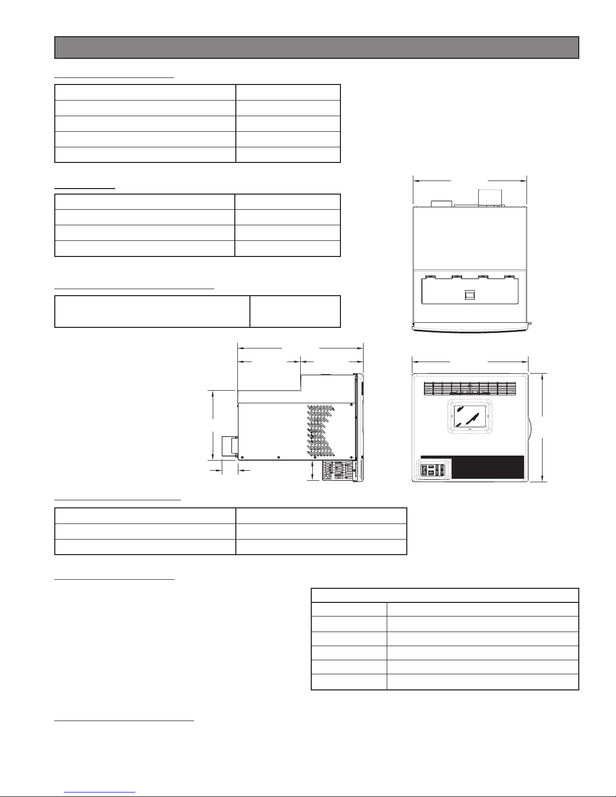
Heating Specications
Height 21⅜ in. [543mm]
Width 22½ in. [572mm]
Depth 27⅛ in. [689mm]
Weight 126½ lbs. [57.5kg]
Dimensions
1 BTU output will vary depending on the quality of fuel. Use
PFI listed fuels for the best results.
2 Heating capacity will vary depending on floor plan
layout of your home, degree of insulation, and the outside
temperature.
3 Pellet size may effect the actual rate of fuel feed and burn
times. Fuel feed rates may vary by as much as 20%. Use PFI
listed fuel for best results.
Electrical Rating 110-120 volts, 60 HZ, 3.0 Amps
Watts (operational) 175 (approx.)
Watts (igniter running) 425 (approx.)
Electrical Specications
Minimum Cut-out / Window Opening
inches [milimeters]
14” x 22¾”
[356 x 578]
Window / Cut-Out Dimensions
Specications
Heat Output116,400 BTU/hr.
Heating Capacity2500 - 1,000 sq. ft.
Fuel Burn Rate3¾ - 2½ lbs./hr.
Burn Time (lowest setting) approx. 35-40 hrs.
Hopper Capacity approx. 30 lbs.
Pellet Fuel Institute (PFI) Premium Standards
Min. Density 40 lbs. per cubic ft.
Size ¼” to 5/16” diameter, length no greater than 1½”
Heat Output 8,200 BTU/lb
Moisture Content 8% by weight or less
Ash Content 1% by weight
Salt Content 300 parts per million or less
SAFETY AND COMPLIANCE
Your Pellet heater has been safety tested and listed to ASTM E 1509-04 and ULC S627-00, by Intertek Testing
Services in Portland, Oregon, USA.

6Ussc
Read this entire manual before you install and use your Pellet heater. Failure to follow instructions may
result in property damage, bodily injury, or even death!
Before installing your heater, you must perform an initial burn in an OUTSIDE environment. Follow the Start-
Up Procedure in the Operation section of this manual.
Your Eco-Aire heater may be installed to code in either a conventional or mobile home (see SPECIAL MOBILE
HOME REQUIREMENTS).
It is recommended that only a authorized technician install your heater, preferably a National Fireplace Institute
(NFI) certied specialist.
This heater must be installed through an opening on an exterior wall. The heater may be installed in an existing
window or opening cut through a wooden, brick, or masonry wall.
Once the desired location is selected, and before cutting a hole, check the outside of the structure for
anything obstructing clearances to the exhaust vent. Also clear away leaves, shrubs/bushes, or trees that may
be around the exhaust outlet.
IMPROPER INSTALLATION: The manufacturer will not be held responsible for damage caused by the
malfunction of a heater due to improper venting or installation. Call (800) 750-2723 and/or consult a
professional installer if you have any questions.
INSTALL VENT AT CLEARANCES SPECIFIED ABOVE.
Your Eco-Aire heater comes pre-assembled with
the exception of the Spark Suppressor that needs
to be attached to the rear of the unit on the ex-
haust outlet.
DO NOT OPERATE THIS HEATER WITH THE SPARK SUP-
PRESSOR REMOVED!
Using the hardware and gasket supplied, attach
the suppressor to the rear of the unit as shown in
the illustration.
VENT TERMINATION CLEARANCES:
A) Minimum 4-foot [1.2m] clearance below or
beside any door or window that opens.
B) Minimum 1-foot [0.3m]clearance above any
door or window that opens.
C) Minimum 2-foot [0.6m] clearance from any
adjacent building.
D) Minimum 7-foot [2.1m] clearance from any
grade when adjacent to public walkways.
E) Minimum 2-foot [0.6m] clearance above any
grass, plants, or other combustible materials.
F) Minimum 4-foot [1.2m] clearance from an
forced air intake of any appliance.
G) Minimum 2-foot [0.6m] clearance below eves
or overhang.
H) Minimum 1-foot [0.3m] clearance horizontally
from combustible wall.
NOTICE: This unit shall be installed in such a way that the exhaust gases are directed so they do not jeopardize
people, overheat combustible structures, or enter buildings.
Assembly
Installation
Ussc7
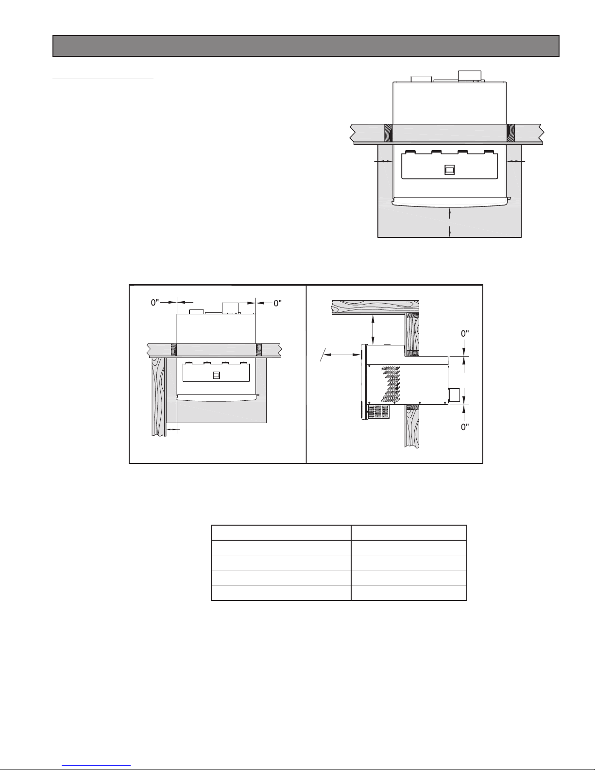
FLOOR PROTECTION
This heater must have a non-combustible oor protector
(ember protection) installed beneath it if the floor is of
combustible material. If a oor pad is used, it should be UL
listed or equal. The oor pad or non-combustible surface
should be large enough to extend a minimum of 6-inches
[152mm] in front and 2-inches [51mm] on each side of the
heater.
Canadian Installations require a minimum of 450 mm [17.7”]
beyond the front of the unit and 200mm [7.8”] beyond each
side of the unit
Your heater will need a minimum 18½” x 34½” oor protector.
A Floor Protector of ¼ inch thick is recommended for this
installation.
2 [51] 2 [51]
6 [152]
inches [milimeters]
2” [51mm]
6”
[152mm]
60”
[1.5M]
Clearances to Combustibles
Combustible Clearance
Floor (Allow for brace) 6 inches [152mm]
Left / Right 2 inches [51mm]
Ceiling (Allow for fuel loading) 6 inches [152mm]
Front 60 inches [1.5M]
General Installation Clearance:
This unit is approved for Zero Clearance to any installed combustible surface such as the window sash, sill,
or wooden structure in a wall installation. However, clearance should be considered for ease of installation
and removal for maintenance and repair.
General Installation Notes
♦ Do not install heater where the exhaust will terminate in a window well or any opening below ground level.
♦ Special precautions may be required to prevent snow build-up within 12 inches of the air intake.
♦ Clearances around heater must provide adequate room for service, cleaning, and air circulation.
♦ Residential Garage Installation: The heater shall be located or protected so it is not subject to damage by
a moving vehicle. Use care when selecting a good location within the garage. DO NOT locate the heater
where the discharge air will be directed onto a nearby parked vehicle. DO NOT store containers of paint,
gasoline, or other ammable liquids in the same area as the heater, inside or outside the home or structure.
Installation
8Ussc
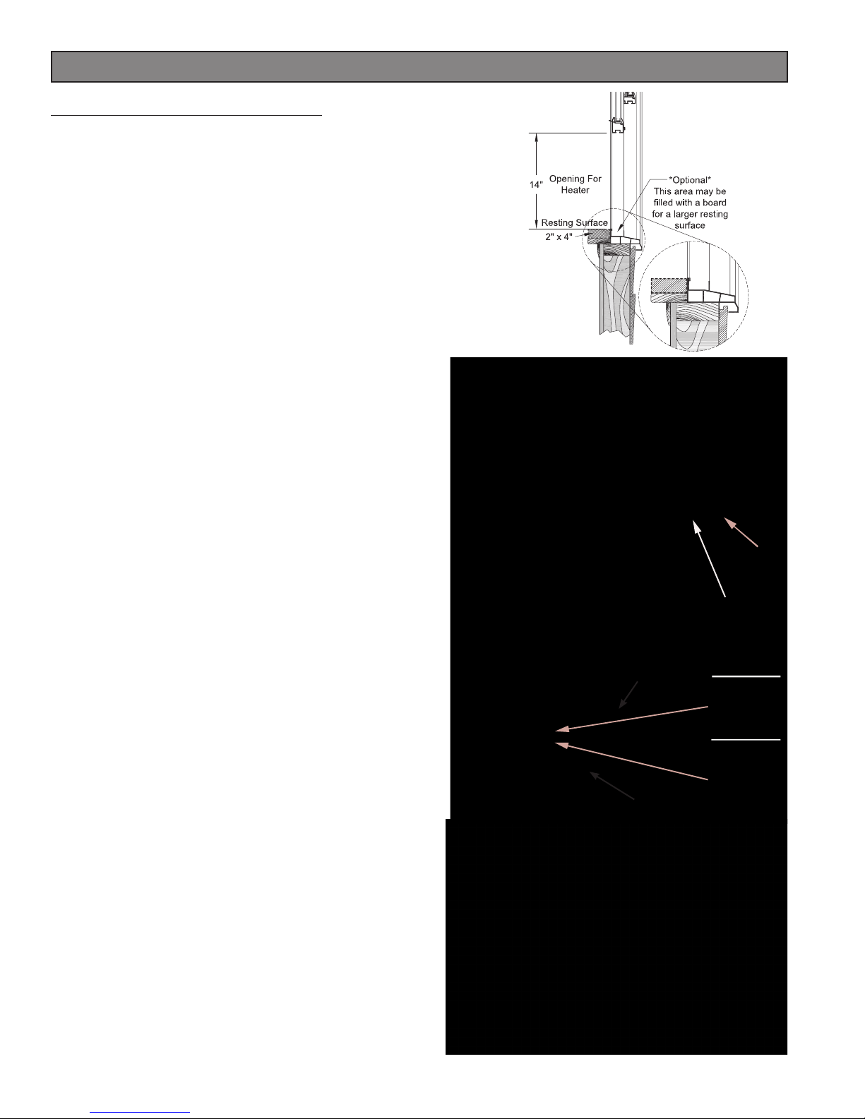
When Installing your heater in a window
• Select a window of adequate size and with the ap-
propriate clearances needed for a safe installation.
The mounting hardware supplied is designed for the
appliance to be installed in the approximate center
of the window. You will need to provide the attach-
ing hardware, (i.e. screws, wall anchors, etc.) of which
should be suitable for mounting to the outside surface
of your home or structure. You may choose to utilize
the supplied mounting system or a conguration of your
own. However, U.S. Stove shall not be liable for faulty
mounting congurations.
• Depending on your application, a solid resting surface
will need to be established on the window sill. If your
selected window’s bottom ange rises above the sill, a
board will need to be placed and should be level with
or just rise above that ange. Use the illustration to the
right for reference.
• The supplied support brackets will need to be mounted
before inserting the heater into the window. These
pieces will mount to the outside of the home or structure.
• Assemble the two Knee Braces to the Retention Bracket
using a washer (d) and nut (e) for each side. Tighten the
nuts then back them off to allow the bracket to slide
back and forth along the knee braces.
• Using a carpenter’s level or a straight edge, determine
the height of the retention bracket in relation to the
resting surface of the heater. Once you’ve determined
that mark, locate the mounting assembly 1/4” lower to
allow for precipitation runoff.
• Attach the Knee Braces to the home or structure using
the hardware that you have determined suitable for
your application.
• Once you’ve stabilized the Knee Braces, you’re ready
to insert the heater into the window/opening. Slide the
heater thru the window or opening. Insert item “a” in the
center hole of the bottom but don’t tighten fully. Allow
item “a” to engage the SLOT in the retention bracket
as shown in the illustration to the right. Slide the heater
into the window opening until it stops. The heater should
either stop on the window sash at the back of the hop-
per lid or on the window sill when it reaches the fan
enclosure, whichever comes rst.
• Align the holes in the retention bracket and heater bot-
tom. Insert a washer (b) and bolt (c), and tighten.
• Tighten the two nuts (e) on the knee braces.
• Using the window sill brackets, mount them to the side
of the heater, using the existing cabinet screws, then to
the top of the window sill with the screws provided. See
illustration on the following page.
• Lower the sash onto the top of the heater and proceed
to install the window insulation/ller panels.
Window Installation
SLOT
a
b
c
d
e
Retention
Bracket
Knee
Braces

Ussc9
A
B
WINDOW Sill MOUNT-
ING BRACKETS
Window Installation
Installing the ller panels
• Begin by assembling the left and right side ller panels together.
Slide part A into part B; Notice the range of adjustment. If the
openings on each side of the heater exceeds this range, you will
have to ll the gap by other means necessary to keep the window/
opening weather tight. Otherwise, proceed.
• Place the panel assembly against the bottom of the window sash
and bottom of the window frame. Slide apart the two sections
until the ange on part A meets the inside of the window frame
and the ange on part B meets the side of the heater. Using a drill
with a 5/16” socket bit, drive the self-tapping screw through the
hole in part A into part B. This sets the width of the panels.
• Peel away the protective coating from the two-sided tape on the
anges and adhere it to the window and framing.
• Measure the ller panel width and cut the foam insulation to size.
Peel away the coating on the tape strips and apply the foam to
the panels.
• Finish the install by sealing around the outside of the heater and
ller panels with a weatherproong silicone sealant.
TWO-SIDED TAPE
TWO-SIDED TAPE
SCREW
CUT-TO-FIT

10Ussc
When Installing your heater in an exterior wall
• Select a wall to the exterior of the building. This wall should
have the required clearance to combustibles inside and out
mentioned earlier in this manual. Make certain that electrical
wires, conduit, water or gas pipes do not pass through the area
you have selected
• USSC suggest the following installation illustrated to the right,
however, you may frame the hole cut out to your discretion.
A sturdy base for the heater to rest should be established.
• At the desired height, mark the hole location for your heater.
Measure and cut the appropriate size hole for your installation.
The cut out should border a wall stud. The next wall stud will
need to be cut.
Build a frame of 2 x 4’s at the dimensions suggested and secure
it in place by attaching it to the available studs.
• Before installing the heater, install the Knee/Support Braces.
• Install the knee/support braces supplied. See the previous page for installation. You may use the hardware
supplied or purchase the appropriate fasteners from your local hardware store for the type of material you
are securing into.
• Seal around the heater with silicone or caulking to protect against the weather.
[648mm]
[572mm]
[356mm] [432mm]
WARNING! - DO NOT INSTALL IN A SLEEPING ROOM
CAUTION! - THE STRUCTURAL INTEGRITY OF THE MOBILE HOME FLOOR, WALL, AND CEILING/ROOF MUST BE
MAINTAINED.
• The heater must be permanently attached to the wall.
• The heater must be electrically grounded to the steel chassis of the mobile home with 8 GA copper wire
using a serrated or star washer to penetrate paint or protective coating to ensure grounding.
• When moving your mobile home, the heater must be removed while the mobile home is being relocated.
After relocation, heater may be reinstalled and securely fastened.
• Check with your local building ofcials as other codes may apply.
Mobile Home Installation Requirements
Wall Installation
Other manuals for 2400
1
Table of contents
Other Eco-Aire Heater manuals

Popular Heater manuals by other brands


Siemens
Siemens DE 1113415 Installation and operating instructions

Dimplex
Dimplex RCE 050 Installation and operating instructions

Fakir
Fakir HK 2200 Operation manual

Quality Heating
Quality Heating QH-H4 manual

Combustion Research
Combustion Research Reflect-O-Ray EDS-4DI Installation, operating, maintenance and parts manual

Bestron
Bestron AWH2000 instruction manual


