Ecoflam MAIOR P 300.1 AB User manual

420010362200
24.05.2011
MAIOR P 300.1 AB
MAIOR P 400.1 AB
MOTORIDUTTORE
AIR DAMPER MOTOR
SERVOMOTEUR
MOTORREDUCTOR
ЭЛЕКТРОПРИВОД ВОЗДУШНОЙ ЗАСЛОНКИ
BRUCIATORI DI GASOLIO
OIL BURNERS
BRULEURS A MAZOUT
QUEMADOR DE GASOLEO
ДИЗЕЛЬНЫЕ ГОРЕЛКИ
IT
EN
FR
ES
RU

mbar
1500 2000 2500 3000 3500 4000
10
12
14
16
1000
-2
0
2
4
6
8
500
MAIOR P 300.1
MAIOR P 400.1
40 80 120 160 200 240 280 320
kW
kg/h
CARATTERISTICHE TECNICHE
MODELLO MAIOR P 300.1 AB MAIOR P 400.1 AB
Portata termica max. kcal/h 2.586.000 3.362.000
kW 3.000 3.900
Portata termica min. kcal/h 867.300 1.127.500
kW 1.000 1.300
Max. portata gasolio kg/h 250 350
Min. portata gasolio kg/h 85 110
Tensione alimentazione 50 Hz V 230/400 230/400
Potenza motore kW 7,5 9
Giri -minuto Nº 2.800 2.800
Trasf. accensione kV/mA 13/35 13/35
App. controllo fiamma LANDIS LMO 44 LMO 44
Combustibile: gasolio kcal/kg 10.200 max. visc 1,5°E a 20°C
CURVE DI LAVORO
PRESSIONE IN CAMERA DI COMBUSTIONE
PORTATA
DIMENSIONI DI INGOMBRO
I
M
L
ED - D1
F
G
C
B
A
SUNTEC
H1
MODELLI ABCDD1EFGH1I LM
Maior P 300.1 AB 1055 502 553 330 530 810 290 471 746 315 315 M16
Maior P 400.1 AB 1100 547 553 345 545 810 320 471 746 315 315 M16
D = testa corta D1 = testa lunga
IT 420010362200 Maior P 300.1/400.1 AB
2

2
1345
6
7
INSTALLAZIONE DEL BRUCIATORE
1 - BRUCIATORE
2 - DADO
3 - RONDELLA
4 - GUARNIZIONE ISOMART
5 - PRIGIONIERO
6 - CALDAIA
7 - MATERIALE DI RIEMPIMENTO
CIRCUITO IDRAULICO
1 - FLESSIBILI
2 - FILTRO
3 - RUBINETTO
4 - ASPIRAZIONE
5 - RITORNO
4
5
VS
V2
V1
V3
1
1
23
ALIMENTAZIONE COMBUSTIBILE
La lunghezza corretta delle tuba-
zioni è data dalla somma di tutti i
tratti rettilinei orizzontali, verticali
e delle curve. L’altezza statica di
aspirazione è (max. 3.5m) data
dalla distanza tra la valvola di
fondo e l’asse della pompa del
bruciatore. La depressione non
deve superare 0,45 bar; un valore
maggiore potrebbe causare un
deterioramento della pompa con
conseguente aumento dei rumori
meccanici ed eventuale rottura.
H
H
H
(m)
ø 14 mm ø 16 mm
0
0,5
1
2
3
3,5
16
18
20
25
29
31
29
33
37
44
52
55
J 7
(m)
H
(m)
ø 14 mm ø 16 mm
0
0,5
1
2
3
3,5
16
14
12
7
3
1
29
26
22
14
7
4
J 7
(m)
TA2C
(m)
TA2C
(m)
Bitubo dalla sommità del serbatoio
Bitubo in aspirazione
Lunghezza tubazioni
Lunghezza tubazioni
4
5
VS
V2
V1
IT
420010362200 Maior P 300.1/400.1 AB
3

UGELLO PRESSIONE POMPA(bar)
GPH 10 11 12 13 14 15 16
2,50 9,50 9,97 10,41 10,83 11,24 11,64 12,02
3,00 11,40 11,96 12,49 13,00 13,49 13,96 14,42
3,50 13,30 13,95 14,57 15,17 15,74 16,29 16,83
4,00 15,20 15,94 16,65 17,33 17,99 18,62 19,23
4,50 17,10 17,94 18,73 19,50 20,24 20,95 21,63
5,00 19,00 19,93 20,82 21,67 22,48 23,27 24,04
5,50 20,90 21,92 22,90 23,83 24,73 25,60 26,44
6,00 22,80 23,92 24,98 26,00 26,98 27,93 28,84
6,50 23,70 25,91 27,06 28,17 29,23 30,26 31,25
7,00 26,60 27,90 29,14 30,33 31,48 32,58 33,65
7,50 28,50 29,90 31,22 32,50 33,73 34,91 36,05
8,30 31,54 33,08 34,55 35,97 37,32 38,63 39,90
9,50 36,10 37,87 39,55 41,17 42,72 44,22 45,67
10,50 40,06 41,73 43,74 45,41 47,20 48,90 50,50
12,00 45,60 47,80 50,00 52,00 54,00 55,90 57,70
13,80 52,40 55,00 57,50 59,80 62,10 64,20 66,30
15,30 58,10 61,00 63,70 66,30 68,80 71,10 73,60
17,50 66,50 69,80 72,90 75,80 78,70 81,50 84,10
19,50 74,10 77,70 81,20 84,50 87,70 90,80 93,70
21,50 81,70 85,70 89,50 93,20 96,70 100,10 103,40
24,00 91,20 95,70 99,90 104,00 107,90 111,70 115,40
28,00 106,40 111,60 116,60 121,30 125,90 130,30 134,60
30,00 114,00 119,60 124,90 130,00 134,90 139,60 144,20
GPH PORTATA kg/h
PORTATA UGELLI
DELAVAN B - MONARCH PLP
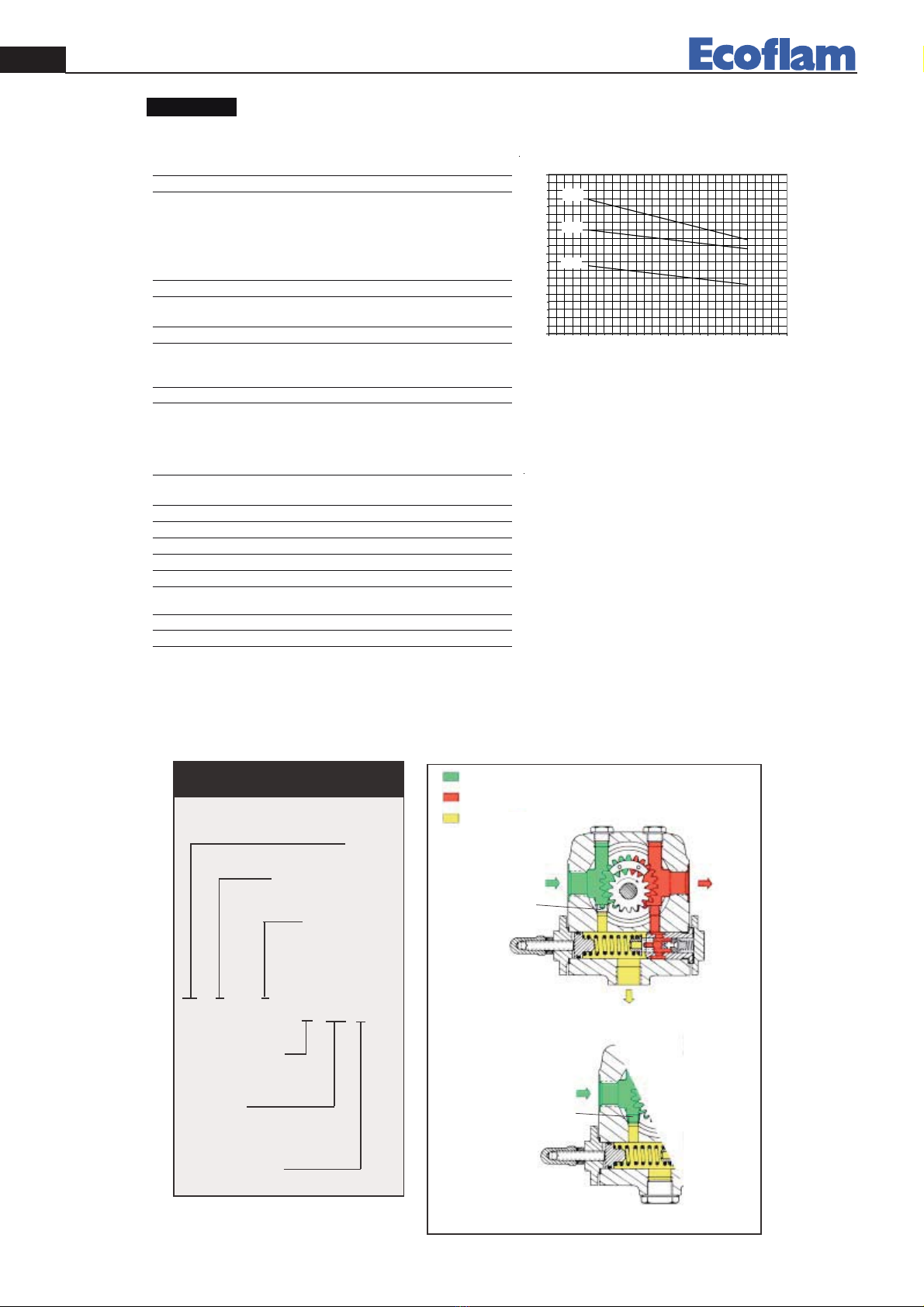
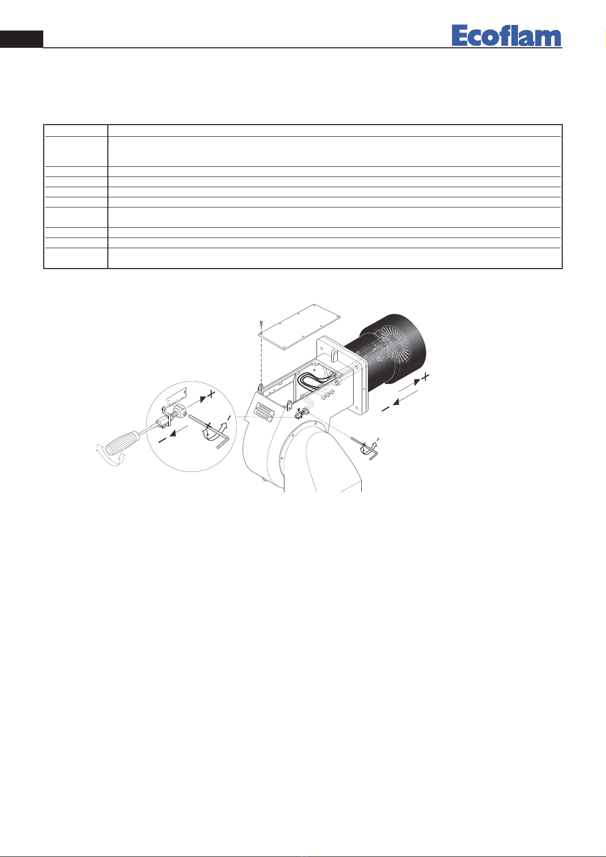
Utilizzare solo la apposita chiave fornita in dotazione pre rimuovere l’ugello, facendo attenzione a non danneggiare gli
elettrodi. Montare il nuovo ugello con la medesima cura.
N.B.: Verificare sempre la posizione degli elettrodi dopo il montaggio dell’ugello (vedi figura). Una posizione errata
può comportare problemi di accensione.
PULIZIA E SOSTITUZIONE DELL’UGELLO
5÷6 mm
3÷4 mm
5÷6 mm
3÷4 mm
SUNTEC J 7 C 1000
6
5
3
2
SUNTEC
SUNTECSUNTEC
14
SUNTEC TA2C4
INNESCO E REGOLAZIONE DELLA POMPA GASOLIO
1 - ASPIRAZIONE
2 - RITORNO
3 - SFIATO E PRESA
MANOMETRO
4 - PRESA VUOTOMETRO
5 - REGOLAZIONE
PRESSIONE
6 - ALL' UGELLO
1
2
5
6
34
IT 420010362200 Maior P 300.1/400.1 AB
4

CONTROLLARE:
- Che le tubazioni siano perfettamente a tenuta;
- Che siano usati tubi rigidi (preferibilmente di rame), ove possibile;
- Che la depressione in aspirazione non ecceda 0,45 bar, per evitare che la pompa entri in cavitazione;
- Che la valvola di fondo sia dimensionata correttamente;
La pressione della pompa viene regolata al valore di 12 bar (13 bar Maior P 300) durante il collaudo del bruciatore.
Prima di avviare il bruciatore, spurgare l’aria contenuta nella pompa attraverso la presa del manometro. Riempire le
tubazioni di gasolio per facilitare l’innesco della pompa. Avviare il bruciatore e verificare la pressione di alimentazione
della pompa. Se l’innesco della pompa non dovesse avvenire durante il primo prelavaggio, con conseguente, successiva
entrata in blocco del bruciatore, riarmarne il blocco per riavviarlo, premendo il pulsante rosso sull’apparecchiatura di
controllo. Se, ad innesco della pompa avvenuto, il bruciatore dovesse andare in blocco dopo la fase di prelavaggio, a
causa di una caduta di pressione del gasolio nella pompa, riarmarne il blocco per riavviarlo. Non permettere che la
pompa funzioni per più di tre minuti senza gasolio. Nota: prima di avviare il bruciatore, assicurarsi che il tubo di ritor-
no sia aperto. Una sua eventuale occlusione provocherebbe una rottura dell’organo di tenuta della pompa.
IT
420010362200 Maior P 300.1/400.1 AB
5
IDENTIFICAZIONE
DELLA POMPA
(Non tutte le combinazioni sono disponibili.
Contattare Suntec)
J : regolazione della pressione
Capacità dell'ingranaggio
(vedi curve di portata pompa)
Filtro
Senso di rotazione
e posizione attacco
mandata all'ugello
(vista lato albero)
A:rotazione oraria /
attacco mandata destra.
B: rotazione oraria /
attacco mandata sinistra.
C: rotazione antioraria /
attacco mandata sinistra.
D: rotazione antioraria/
attacco mandata destra.
Campo di pressione
C: 10-21bar
E: 10-30 bar
J 6 C A C 1 001 5 P
Montaggio a flangia
000 : attachi conici;
funzione di taglio.
001: attachi cilindrici;
funzione di taglio.
002 : attachi cilindrici;
raccordo all'ugello forato,
senza taglio.
Numero di revisione
5 : per J4 ed J6
4 : per J7
Installazioni
P : installazioni a 2 tubi,
con grano di by-pass inserito
nel foro di ritorno.
Ingranaggio
Tenuta
albero
Ritorno
all'aspirazione
Grano
di by-pass
inserito
Grano
di by-pass
tolto
Attacco
manometro
pressione
All'ugello
Olio in aspirazione
Olio in pressione
Ritorno dell'olio non
utilizzato al serbatoio
o all'aspirazione
Attacco
vuotometro
Vite di regolazione
della pressione
INSTALLAZIONE
MONOTUBO
INSTALLAZIONE
A2 TUBI
Aspirazione
Ritorno
Retorno
chiuso
DATI TECNICI POMPA SUNTEC J
NB : Per impianti monotubo, togliere il grano di by-pass inserito sull'attacco di ritorno e chiudere l'attacco di ritorno
mediante un tappo d'acciaio ed una rondella.

6
420010362200 Maior P 300.1/400.1 AB
IT
0
100
200
300
400
5 101520253035
J7
J6
J4
Ref :SK264 -20/03/2001
DATI TECNICI
Generalità
Montaggio a flangia conforme agli standardEN 225.
Modello1000 Modelli 1001/1002
Attacchi Conici cilindrici in accordo con ISO 228/1
Entrataeritorno 1/4"NPTF G 1/2
Uscitaall'ugello 1/8"NPTF G 1/4
Attacco manometropressione 1/8"NPSF G 1/8
Attacco vuotometro1/4"NPTF G 1/2
Funzione della valvola regolazione della pressione etaglio (salvoJ1002).
Filtrosuperficie utile :45 cm²
grado di filtraggio :170 μm
AlberoØ 11mm in accordo con standardEN 225.
Grano di by-pass inseritonel forodi ritorno per installazione a2tubi;
da toglierecon chiavetipoAllen 3/16" per
installazione monotubo.
Peso 4 kg
Dati idraulici
Campodi pressione all'ugello C :10 -21 bar
E:10 -30 bar
Taraturadi fabbrica 12 bar
Campoviscosità2-75 mm²/s (cSt)
Temperaturaolio 0 -90°C nella pompa.
Pressione entrata1,5bar max.
Pressione ritorno 1,5bar max.
Altezzadi aspirazione 0,45 bar max. vuotoper evitarela separazione dell'aria
dall'olio.
Velocità 3600 gpmmax.
Coppia (a45 gpm) 0,30 N.m
Lecaratteristiche indicatetengono contodi unmargine
di usura. Non aumentarele misuredella pompaquando
si sceglie la capacitàdell'ingranaggio.
Viscosità= 5cSt -Velocità= 2850 gpm
Portata(L/h)
Portata della pompa
Pressione (bar)
DATI TECNICI POMPA SUNTEC TA
NB : Tutte le pompe TA sono consegnate per installazione bitubo (grano di by-pass inserito sull' attacco vuotometro).
Per impianti monotubo, togliere il grano di by-pass e chiudere l'attacco di ritorno mediante un tappo d'acciaio ed una
rondella.
IDENTIFICAZIONE
DELLA POMPA
(Non tutte le combinazioni sono disponibili
Contattare Suntec)
TA :tipo
Capacità dell'ingranaggio
(vedi curvedi portata pompa)
Senso di rotazione
(vista lato albero)
A : rotazione oraria.
C:rotazione anti oraria.
TA 2A40 10 5
Campo di pressione :
30 :7-30 bar
40 :7-40 bar
Corpo con
alloggiamento
per preriscaldatore
Numero di revisione
Ingranaggio
Grano
diby-pass
tolto
Attacco
manometro
pressione
All'ugello
Olioinaspirazione
Olioinpressione
Ritorno dell'olio
non utilizzato
alserbatoioo
all'aspirazione
Attacco
vuotometroo
misurapresione
dientrata
Vitediregolazione
dellapressione
INSTALLAZIONE
MONOTUBO
Aspirazione
Ritorno
chiuso
Grano
diby-pass
inserito
INSTALLAZIONE
BITUBO
Ritorno
Aspirazione

7
420010362200 Maior P 300.1/400.1 AB IT
Dopo aver eseguito l’installazione del bruciatore, verificare i seguenti punti:
- Tensione di alimentazione del bruciatore ed i fusibili di protezione di rete.
- I collegamenti del motore. - La corretta lunghezza delle tubazioni e la loro tenuta.
- Il tipo di combustibile, che deve essere adatto al bruciatore. - Il collegamento dei termostati caldaia e delle varie sicu-
rezze. - Il senso di rotazione del motore. - La corretta taratura della protezione termica del motore.
Quando tutte queste condizioni sono verificate e soddisfatte, si può procedere con il collaudo del bruciatore.
Dare tensione al bruciatore. L’apparecchiatura di controllo alimenterà, allo stesso tempo, sia il trasformatore di accensio-
ne che il motore del bruciatore, che provvederà ad effettuare un prelavaggio della camera di combustione per un perio-
do di 20 secondi circa. Al termine del prelavaggio, l’apparecchiatura di controllo apre le elettrovalvole della pompa gaso-
lio e quella del 1° stadio (Bassa fiamma), il trasformatore d’accensione produce una scintilla ed il bruciatore si accende.
Dopo l’intervallo di sicurezza di 5 secondi, ad accensione avvenuta, l’apparecchiatura di controllo disinserisce il trasfor-
matore di accensione quindi, dopo altri 10 secondi, aziona il servocomando dell’aria alla massima apertura ed apre
l’elettrovalvola del 2° stadio(Maior 300) e 3° stadio (Maior 400) (Alta fiamma). In caso di accensione difettosa, l’appa-
recchiatura di controllo causa il blocco del bruciatore entro 5 secondi. In questo caso, il riarmo manuale del bruciatore
non potrà avvenire prima che siano trascori 30 secondi dall’entrata in blocco. Per avere una combustione ottimale,
occorrerà regolare la portata dell’aria in ALTA e BASSA fiamma, seguendo le istruzioni fornite più avanti. Durante tale
fase, si potrà passare manualmente dalla posizione ALTA fiamma ( II ) a quella di BASSA fiamma ( I ), e viceversa, tra-
mite l’interruttore di ALTA/BASSA fiamma. Al termine delle regolazioni, lasciare l’Interruttore in posizione II (Alta
fiamma). La pressione di alimentazione della pompa gasolio dovrà aggirarsi sui 12 bar.
AVVIAMENTO E REGOLAZIONE DEL BRUCIATORE
4020 30 3510 15 255
1000
1200
1400
200
400
0
600
800
TA5
TA4
TA3
TA2
0
900
1500
1100
1300
100
300
500
700
Generalità
Montaggio a flangia
Attacchi cilindrici in accordo con ISO 228/1
Entrata eritorno G 1/2"
Uscita all'ugello G 1/2"
Attacco manometro pressione G 1/4"
Attacco vuotometro G 1/4"
Albero Ø 12 mm
Grano di by-pass inserito nel foro di attacco vuotometro
per installazione a2tubi ;
da togliere con chiavetipo Allen 3/16" per
installazione monotubo
)3AT(gk7,5-)2AT(gk4,5oseP
6kg (TA4) - 6,4 kg (TA5)
Dati idraulici
Campo di pressione 30 :7-30 bar
all'ugello 40 :7-40 bar
Taratura di fabbrica 30 bar
Campo viscosità 4 -450 cSt
Temperatura olio 0 -140°C max. nella pompa
Pressione entrata installazioni agasolio :0,45 bar max. vuoto per
evitare la separazione dell'aria dall'olio
installazioni anafta :5bar max.
Pressione ritorno installazioni agasolio :5bar max.
installazioni anafta :5bar max.
Velocità 3600 gpm max.
Coppia di spunto 0,30 N.m
Scelta del riscaldatore
Cartuccia Ø 12 mm
Raccordo di collegamento in accordo con DIN40430 -NFC 68190 (N° 9elec.)
Potenza 80-100 W
Portata (L/h) Portata dellapompa
Pressione
(bar)
Viscosità = 200 cSt
20 cSt
5cSt - Velocità =2850 gpm
I dati indicati si riferiscono apompe nuove, senzausura.
2850 gpm

REGOLAZIONE TESTA DI COMBUSTIONE
1
2
1234567
8
420010362200 Maior P 300.1/400.1 AB
IT
SOLO PER APPARECCHIATURA LANDIS LMO 44
In caso di blocco é disponibile l’indicazione della causa che ha provocato il blocco. Operare come segue: con l’apparec-
chiatura in blocco (led rosso acceso) tenere premuto il pulsante di sblocco per più 3 secondi, quindi rilasciarlo. Il led
rosso inizierà a lampeggiare indicando la causa secondo la seguente tabella:
Codice errore Possibile causa
2 lampeggi Assenza di fiamma al termine del tempo di sicurezza all’accensione «TSA»
- elettrovalvole difettose - rilevatore fiamma difettoso - regolazione bruciatore errata
- elettrodi difettosi
3 lampeggi Non utilizzati
4 lampeggi Luci estranee durante la fase di pre-ventilazione
5 lampeggi Non utilizzati
6 lampeggi Non utilizzati
7 lampeggi Troppe mancanze di fiamma durante il funzionamento (superato il limite del n° di ripetizioni del ciclo) - elettrovalvole difet
tose - rilevatore fiamma difettoso - regolazione bruciatore errata
8 lampeggi Controllo del tempo riscaldamento combustibile
9 lampeggi Non utilizzati
10 lampeggi Contatti in uscita difettosi o guasto del dispositivo interno

9
420010362200 Maior P 300.1/400.1 AB IT
LANDIS SQM 50.381A2
MAIOR P 400
I - Camma di regolazione della posizione di apertura in
3afiamma (potenza max.)
II - Camma di regolazione della posizione di apertura in
1afiamma (potenza min.)
III - Camma di regolazione della posizione di apertura in
2afiamma
IV - Ritorno da 3a fiamma a 2a fiamma (sempre 5° superiore
alla camma di regolazione della 2a fiamma)
V - Camma di consenso all’apertura dell’elettrovalvola della
2afiamma.
VI - Camma di consenso all’apertura dell’elettrovalvola della
3afiamma.
VII - Camma non utilizzata.
VIII - Camma non utilizzata.
REGOLAZIONE DELLA PORTATA DELL’ARIA DI COMBUSTIONE (ALTA-BASSA FIAMMA)
Togliere il coperchio per accedere alle camme di regolazione. Lo sposta-
mento delle camme va effettuatocon l’ausilio dell’apposita chiavetta in
dotazione. Descrizione :
MAIOR P 300
I - Camma di regolazione della posizione di apertura in
2afiamma (potenza max.)
II - Camma di regolazione della posizione di apertura in
1afiamma (potenza min.)
III - Controllo posizione motoriduttore all’avviamento.
IV - Camma di consenso all’apertura dell’elettrovalvola
della 2afiamma.
V - Camma non utilizzata.
VI - Camma non utilizzata.
VII - Camma non utilizzata.
VIII - Camma non utilizzata.
Tutti i bruciatori vengono collaudati a 400V - 50Hz trifase per i motori, e 230V - 50Hz monofase con neutro per le
apparecchiature ausiliarie. Se si rendesse necessario alimentare il bruciatore con 230V - 50Hz trifase senza neutro,
modificare i collegamenti sul motore e sulla morsettiera come indicato in figura. Proteggere la linea di alimentazione del
bruciatore con fusibili adeguati.
COLLEGAMENTI ELETTRICI

ANOMALIE DI FUNZIONAMENTO
Il bruciatore non si avvia.
- Interruttore generale in posizione “0”
- Fusibili saltati.
- Termostati caldaia aperti.
- Apparecchiatura di controllo difettosa.
Il bruciatore effettua il prelavaggio, ma non si accende e va in blocco subito dopo.
- Apparecchiatura di controllo difettosa.
- Trasformatore difettoso..
- Elettrodi sporchi.
- Elettrodi difettosi.
- Elettrodi in posizione errata.
- Ugelli otturati.
- Ugelli eccessivamente usurati.
- Filtri intasati.
- Pressione gasolio troppo bassa.
- Portata d’aria di combustione eccessivamente elevata in rapporto alla portata dell’ugello.
Il bruciatore si accende ma va in blocco subito dopo.
- Apparecchiatura di controllo difettosa.
- Ugelli otturati.
- Ugelli eccessivamente usurati.
- La fotocellula non vede la fiamma.
- Filtri intasati.
- Pressione gasolio troppo bassa.
- Portata d’aria di combustione eccessivamente elevata in rapporto alla portata dell’ugello.
Il bruciatore non passa in 2° (3°) stadio.
- Interruttore manuale di 1° e 2° stadio sulla morsettiera in posizione errata.
- Apparecchiatura di controllo difettosa..
- Bobina dell’elettrovalvola 2° (3°) stadio difettosa.
- Pressione gasolio troppo bassa.
- Filtri intasati.
- Ugello 2° (3°) stadio eccessivamente usurato.
- Ugello 2° (3°) stadio intasato.
- Motoriduttore serranda aria non tarato o difettoso.
IT 420010362200 Maior P 300.1/400.1 AB
10

mbar
1500 2000 2500 3000 3500 4000
10
12
14
16
1000
-2
0
2
4
6
8
500
MAIOR P 300.1
MAIOR P 400.1
40 80 120 160 200 240 280 320
kW
kg/h
TECHNICAL DATA
MODELS MAIOR P 300.1 AB MAIOR P 400.1 AB
Thermal power max. kcal/h 2.586.000 3.362.000
kW 3.000 3.900
Thermal power min. kcal/h 867.300 1.127.500
kW 1.000 1.300
Max. flow rate light oil kg/h 250 350
Min. flow rate light oil kg/h 85 110
Feeding power 50 Hz V 230/400 230/400
Motor kW 7,5 9
Rpm Nº 2.800 2.800
Ignition transformer kV/mA 13/35 13/35
Control box LANDIS LMO 44 LMO 44
Fuel : light oil kcal/kg 10.200 max. visc 1,5°E a 20°C
WORKING FIELDS
PRESSURE IN THE COMBUSTION CHAMBER
OUTPUT
OVERALL DIMENSIONS
I
M
L
ED − D1
F
G
C
B
A
H
SUNTEC
SUNTEC
SUNTEC
MODELS ABCDD1EFGH1I LM
Maior P 300.1 AB 1055 502 553 330 530 810 290 471 746 315 315 M16
Maior P 400.1 AB 1100 547 553 345 545 810 320 471 746 315 315 M16
D = short head D1 = long head
EN
420010362200 Maior P 300.1/400.1 AB
11

MAXIMUM LENGTH OF SUCTION LINES FOR TWO-PIPE SYSTEM
To correct length of pipes is
calculated by summing up the
length of all vertical and hori-
zontal right sections and bends.
The static suction head will be
the distance between the non-
return valve and the burner’s
pump axle. The depression
must not be greater than 0.45
bar; should it be higher, some
damages could occur to the
pump, with consequent increa-
se in mechanical noises and
,eventually, a failure.
2
1345
6
7
BURNER INSTALLATION
1 - BURNER
2 - NUT
3 - WASHER
4 - GASKET
5 - BOLT
6 - BOILER
7 - GASKET
HYDRAULIC CIRCUIT
1 - HOSE
2 - OIL FILTER
3 - OIL COCK
4 - SUCTION
5 - RETURN
1
1
23
H
H
H
(m)
ø 14 mm ø 16 mm
0
0,5
1
2
3
3,5
16
18
20
25
29
31
29
33
37
44
52
55
J 7
(m)
H
(m)
ø 14 mm ø 16 mm
0
0,5
1
2
3
3,5
16
14
12
7
3
1
29
26
22
14
7
4
J 7
(m)
TA2C
(m)
TA2C
(m)
Two-pipe siphon feed system
Two-pipe lift system
Pipe length
Pipe length
4
5
VS
V2
V1
V3
EN
420010362200 Maior P 300.1/400.1 AB
12
4
5
VS
V2
V1

NOZZLE PUMP PRESSURE (bar)
GPH 10 11 12 13 14 15 16
2,50 9,50 9,97 10,41 10,83 11,24 11,64 12,02
3,00 11,40 11,96 12,49 13,00 13,49 13,96 14,42
3,50 13,30 13,95 14,57 15,17 15,74 16,29 16,83
4,00 15,20 15,94 16,65 17,33 17,99 18,62 19,23
4,50 17,10 17,94 18,73 19,50 20,24 20,95 21,63
5,00 19,00 19,93 20,82 21,67 22,48 23,27 24,04
5,50 20,90 21,92 22,90 23,83 24,73 25,60 26,44
6,00 22,80 23,92 24,98 26,00 26,98 27,93 28,84
6,50 23,70 25,91 27,06 28,17 29,23 30,26 31,25
7,00 26,60 27,90 29,14 30,33 31,48 32,58 33,65
7,50 28,50 29,90 31,22 32,50 33,73 34,91 36,05
8,30 31,54 33,08 34,55 35,97 37,32 38,63 39,90
9,50 36,10 37,87 39,55 41,17 42,72 44,22 45,67
10,50 40,06 41,73 43,74 45,41 47,20 48,90 50,50
12,00 45,60 47,80 50,00 52,00 54,00 55,90 57,70
13,80 52,40 55,00 57,50 59,80 62,10 64,20 66,30
15,30 58,10 61,00 63,70 66,30 68,80 71,10 73,60
17,50 66,50 69,80 72,90 75,80 78,70 81,50 84,10
19,50 74,10 77,70 81,20 84,50 87,70 90,80 93,70
21,50 81,70 85,70 89,50 93,20 96,70 100,10 103,40
24,00 91,20 95,70 99,90 104,00 107,90 111,70 115,40
28,00 106,40 111,60 116,60 121,30 125,90 130,30 134,60
30,00 114,00 119,60 124,90 130,00 134,90 139,60 144,20
GPH OUTPUT kg/h
NOZZLE FLOW RATE
DELAVAN B - MONARCH PLP
Use only the suitable box wrench provided for this operation to remove the nozzle, taking care to not damage the elec-
trodes. Fit the new nozzle with the same care.
Note: Always check the position of electrodes after having replaced the nozzle (see illustration). A wrong position could
cause ignition troubles.
NOZZLE CLEANING AND REPLACEMENT
5÷6 mm
3÷4 mm
5÷6 mm
3÷4 mm
SUNTEC J 7 C 1000
6
5
3
2
SUNTEC
SUNTECSUNTEC
14
SUNTEC TA2C4
PRIMING AND ADJUSTMENT OF OIL PUMP
1 - INLET
2 - RETURN
3 - BLEED AND PRESSURE
GAUGE PORT
4 - VACUUM GAUGE PORT
5 - PRESSURE
ADJUSTMENT
6 - TO NOZZLE
1
2
5
6
34
EN
420010362200 Maior P 300.1/400.1 AB
13

VERIFY:
- That piping system is perfectly sealed;
- That the use of hoses is avoided whenever is possible (use copper pipes preferably);
- That depression is not greater than 0,45 bar, to avoid pump’s cavitation;
- That check valve is suitably designed for the duty;
The pump pressure is set at a value of 12 bar (13 bar Maior P 300.1) during the testing of burners. Before starting the
burner, bleed the air in the pump through the gauge port. Fill the piping with light-oil to facilitate the pump priming.
Start the burner and check the pump feeding pressure. In case the pump priming does not take place during the first
prepurging, with a consequent, subsequent lock-out of the burner, rearm the burner’s lock-out to restart, by pushing
the button on the control box. If, after a successful pump priming, the burner locks-out after the prepurging, due to a
fuel pressure drop in the pump, rearm the burner’s lock-out to restart the burner. Do never allow the pump working
without oil for more than three minutes. Note: before starting the burner, check that the return pipe is open. An even-
tual obstruction could damage the pump sealing device.
EN
420010362200 Maior P 300.1/400.1 AB
14
PUMP
IDENTIFICATION
(Not all model combinations are available.
Consult your Suntec representative)
J : Pressure regulation
Gear set capacity
(see pump capacity curves)
Filter
Shaft rotation
and nozzle location
(seen from shaft end)
A : clockwise rotation/
right hand nozzle.
B: clockwise rotation/
left hand nozzle.
C: anti clockwise rotation/
left hand nozzle.
D:anti clockwise rotation/
right hand nozzle.
Pressure range
C: 10-21bars
E: 10-30 bars
J 6 C A C 1 001 5 P
Flange mounting
000 : conical connection threads
cut-off function
001: cylindrical connection threads
cut-off function
002 : cylindrical connection threads
by-pass nozzle, no cut-off function
Revision number
5 : for J4 and J6
4 : for J7
Installation
P : by-pass plug installed in return port
for two-pipe operation
Pressure
gauge port
Gear set
To nozzle
Pressure
adjustment
Back
to suction
By-pass
plug
inserted
By-pass
plug
removed
Return
Inlet
ONEPIPE
INSTALLATION
Return
plugged
TWOPIPE
INSTALLATION
Vacuum
gauge port
Oil under pressure
Oil under suction
By-passed oil
returned to tank,
or to suction
PUMP SUNTEC J TECHNICAL DATA
NB : For one-pipe installation, the by-pass plug must be removed from the return port and the return port sealed by
steel plug and washer.

15
420010362200 Maior P 300.1/400.1 AB
EN
0
100
200
300
400
510 1520 2530 35
J7
J6
J4
Ref :SK264-20/03/2001
TECHNICALDATA
General
Mounting Flange mounting according toEN225.
Model1000 Models1001/1002
Connection threads ConicalCylindrical(according toISO 228/1)
Inlet and return1/4"NPTF G 1/2
Nozzleoutlet 1/8"NPTF G 1/4
Pressuregauge port 1/8"NPSF G 1/8
Vacuumgauge port 1/4"NPTF G 1/2
Valvefunction Pressureregulating and cut-off (except for 1002 models).
StrainerOpen area :45cm²
Opening size:170 μm
ShaftØ11mm according toEN225.
By-pass plugInserted inreturnport for 2pipesystem;
toberemoved witha3/16" Allen key for 1pipesystem.
Weight4kg
Hydraulic data
Nozzlepressurerange C :10 -21 bars
E:10 -30 bars
Deliverypressuresetting 12 bars
Operating viscosity2-75mm²/s(cSt)
Oil temperature0-90°C inthe pump.
Inlet pressure1,5barsmax.
Returnpressure1,5barsmax.
Suction height0,45barsmax. vacuumtoprevent air separation from oil.
Rated speed 3600 rpmmax.
Torque(@ 45rpm) 0,30 N.m
Pressure(bars)
Viscosity= 5cSt -rated speed = 2850rpm
Datashowntake intoaccount awear margin.
Do not oversizethe pump when selecting the
gear capacity.
Capacity(L/h)
Pump capacity
PUMP SUNTEC TA TECHNICAL DATA
Note : All TA models are delivered for two-pipe system (by-pass plug fitted in vacuum gauge port). For one-pipe
system, the by-pass plug must be removed and the return port sealed by steel plug and washer.
TA :type
TA2A4010 5
PUMP
IDENTIFICATION
(Not all modelcombinations are available
Consultyour Suntec representative)
Gear set capacity
(see pump capacitycurves)
Shaftrotation
(seen from shaftend)
A :clockwise rotation
C:anti clockwise rotation
Pressure range :
30:7-30bars
40 :7-40 bars
Preheater
facility
Revision number
Ingranaggio
Grano
diby-pass
tolto
Attacco
manometro
pressione
All'ugello
Olio in aspirazione
Olio in pressione
Ritorno dell'olio
non utilizzato
alserbatoio o
all'aspirazione
Attacco
vuotometroo
misurapresione
dientrata
Vitediregolazione
dellapressione
INSTALLAZIONE
MONOTUBO
Aspirazione
Ritorno
chiuso
Grano
diby-pass
inserito
INSTALLAZIONE
BITUBO
Ritorno
Aspirazione

16
420010362200 Maior P 300.1/400.1 AB
EN
Once having installed the burner, check the following items:
- The burner power feeding and the main line protection fuses.- The correct length of pipes and that the same are sea-
led.- The type of fuel, which must be suitable for burner.- The connection of boiler’s thermostats and all the safeties.-
The motor rotation direction.- The correct calibration of the motor’s thermal protection.
When all the above mentioned conditions are checked and accomplished, it is possible to go on with burner’s tests.
Power the burner. The control box feeds the ignition transformer and the burner’s motor at the same time, which will
run a prepurging of the combustion chamber for about 20 sec.
At the end of prepurging, the control box opens the fuel pump and the 1st stage (Low flame) solenoid valves, the igni-
tion transformer produces a spark and the burner ignites. After a safety interval of 5 seconds and a correct ignition, the
control box turns off the ignition transformer and, 10 seconds later, sets the motorised air damper to its maximum ope-
ning and opens the 2nd stage solenoid valve (Maior 300) and 3rd stage solenoid valve (Maior 400) (High flame). In
case of faulty ignition, the control box switches the burner into safety condition. In such a case, the manual rearming of
the burner shall not take place before 30 seconds have elapsed from the burner’s safety shutdown. In order to obtain an
optimal combustion, it is necessary adjust the LOW - HIGH flame air flow, according to the instruction given further
on. During such a phase, it will be possible to manually switch between HIGH ( II ) and LOW ( I ) flame and vicever-
sa, through the High/Low flame switch. At the end of the adjusting phase, leave the switch in position II (HIGH
flame). The fuel pump feeding pressure, must remain around 12 bar.
START-UP AND ADJUSTMENT
Inlet end return G1/2"
To nozzle G1/2"
Pressure gauge port G1/4"
Vacuum gauge port G1/4"
4020 30 3510 15 255
1000
1200
1400
200
400
0
600
800
TA5
TA4
TA3
TA2
0
900
1500
1100
1300
100
300
500
700
General
Mounting Flange mounting
Connection threads Cylindrical according to ISO 228/1
Shaft Ø12 mm
By-pass plug Inserted in vacuum gauge port
for 2pipe system;
to be removed with a3/16" Allen key
for 1pipe system
Weight 5,4 kg (TA2) - 5,7 kg (TA3)
6kg (TA4) -6,4kg (TA5)
Hydraulicdata
Nozzle pressure ranges 30 :7-30 bars
40 :7-40 bars
Delivery pressure
setting 30 bars
Operating viscosity 4 -450 cSt
Oil temperature 0 -140°C max. in the pump
Inlet pressure light oil : 0,45 bars max. vacuum to prevent
air separation from oil
heavyoil :5bars max.
Return pressure light oil :5bars max.
heavyoil :5bars max.
Rated speed 3600 rpm max.
Starting torque 0,3 N.m
Choice of heater
Cartridge Ø 12 mm
Fitting according to DIN40430, NFC 68190 (N°9 elec.)
Rating 80-100 W
Data shown are for new pumps, with no allowance for wear.
Pump capacity
Capacity (L/h)
Viscosity = 200 cSt
20 cSt
5cSt - Rated speed =2850 rpm
Pressure
(bars)
2850 rpm

17
420010362200 Maior P 300.1/400.1 AB
EN
LANDIS LMO 44 CONTROL INFORMATION SYSTEM
In case of burner lockout, it is possible to read which cause originated it. Proceed as follows: with the burner in lockout
mode (red LED switched on) keep pressed the lockout button for more than 3 sec. then release it. The red LED will
blink according to the following error code list:
Error Code Possible cause
2 blinks No establishment of flame at the end of «TSA»
- Faulty or soiled fuel valves - Faulty or soiled flame detector - Poor adjustment of burner,
no fuel - Faulty ignition
3 blinks Free
4 blinks Extraneous light on burner start-up
5 blinks Free
6 blinks Free
7 blinks Too many losses of flame during operation (limitation of the number of repetitions)
- Faulty or soiled fuel valves - Faulty or soiled flame detector - Poor adjustment of burner
8 blinks Time supervision oil pre-heater
9 blinks Free
10 blinks Wiring error or internal error, output contacts
FIRING HEAD SETTING
1
2
1234567

All burners are factory tested at 400V - 50Hz 3-phase for motors, and 230V - 50Hz single phase with neutral for auxi-
liary equipments. Should it be necessary to power the burner with 230V - 50Hz, modify the connections on motor and
the terminal board as shown in the picture. Protect the burner supply line with suitable fuses and/or other safety devices
as required by the local regulations on the matter.
ELECTRICAL CONNECTIONS
LANDIS SQM 50.381A2
COMBUSTION AIR FLOW ADJUSTMENT (HIGH-LOW FLAME)
Remove cover to gain access to the adjusting cams. The cams are to
be adjusted through the suitable key provided . Description:
MAIOR P 400
I - Limit switch for air damper “3rd. stage” position
adjustment (Max. power).
II - Limit switch for air damper “1st. stage” position
adjustment (Min. power).
III - Limit switch for air damper “2nd. stage” position
adjustment .
IV - Switches from 3rd stage to 2nd stage
(always 5° bigger than 2nd stage adjusting limit switch)
V - Limit switch for 2nd stage’s solenoid valve
opening release.
VI - Limit switch for 3rd stage’s solenoid valve
opening release.
VII - Limit switch “NOT USED”.
VIII - Limit switch “NOT USED”.
MAIOR P 300
I - Limit switch for air damper “2nd. stage” position
adjustment (Max. power)
II - Limit switch for air damper “1st. stage” position
adjustment (Min. power).
III - Limit switch for ignition flame position adjustment.
IV - Limit switch for 2nd stage’s solenoid valve
opening release..
V - Limit switch “NOT USED”.
VI - Limit switch “NOT USED”.
VII - Limit switch “NOT USED”.
VIII - Limit switch “NOT USED”.
EN
420010362200 Maior P 300.1/400.1 AB
18

TROUBLESHOOTING
The burner does not start.
- Main switch in “0”.
- Fuses are blown.
- Boiler thermostats are in open position.
- Control box is defective.
The burner runs the prepurging but does not ignite and then switches into safety condition.
- Control box is defective.
- Ignition transformer is defective.
- Electrodes are dirty.
- Electrodes are defective.
- Electrodes are in wrong position.
- Nozzles are clogged.
- Nozzles are too worn.
- Filters are clogged.
- Oil pressure too low.
- Combustion air flow rate excessively high related to nozzle’s flow rate.
The burner ignites but then switches into safety condition.
- Control box is defective.
- Nozzles are clogged.
- Nozzles are too worn.
- The photocell does not detect the flame.
- Filters are clogged.
- Oil pressure too low.
- Combustion air flow rate excessively high related to nozzle’s flow rate.
The burner does not switch to High flame.
- 1st(Low flame) and 2nd (High flame) stage manual switch on control board is in wrong position.
- Control box is defective.
- 2nd (3rd) stage solenoid valve coil is defective.
- Oil pressure too low.
- Filters are clogged.
- 2nd (3rd) stage nozzle is too worn.
- 2nd (3rd) stage nozzle is clogged.
- Air damper motor jack not properly adjusted or defective.
EN
420010362200 Maior P 300.1/400.1 AB
19

mbar
1500 2000 2500 3000 3500 4000
10
12
14
16
1000
-2
0
2
4
6
8
500
MAIOR P 300.1
MAIOR P 400.1
40 80 120 160 200 240 280 320
kW
kg/h
CARACTERISTIQUES TECHNIQUES
MODELES MAIOR P 300.1 AB MAIOR P 400.1 AB
Puissance thérmique max. kcal/h 2.586.000 3.362.000
kW 3.000 3.900
Puissance thérmique min. kcal/h 867.300 1.127.500
kW 1.000 1.300
Débit max. kg/h 250 350
Débit min. kg/h 85 110
Tension d'alimentation 50 Hz V 230/400 230/400
Moteur kW 7,5 9
Tours par minute Nº 2.800 2.800
Transformateur kV/mA 13/35 13/35
Coffret de sécurité LANDIS LMO 44 LMO 44
Combustible : mazout kcal/kg 10.200 max. visc 1,5°E a 20°C
COURBE DE TRAVAIL
PRESSION DANS LA CHAMBRE DE COMBUSTION
DEBIT
DIMENSIONS D'ENCOMBREMENT
I
M
L
ED − D1
F
G
C
B
A
H
SUNTEC
SUNTEC
SUNTEC
FR
420010362200 Maior P 300.1/400.1 AB
20
MODELES ABCDD1EFGH1I LM
Maior P 300.1 AB 1055 502 553 330 530 810 290 471 746 315 315 M16
Maior P 400.1 AB 1100 547 553 345 545 810 320 471 746 315 315 M16
D = tete courte D1 = tete longue
Other manuals for MAIOR P 300.1 AB
2
This manual suits for next models
1
Table of contents
Languages:
Other Ecoflam Industrial Equipment manuals