Ecoflo NATURE LOO EXCELET CS Instruction Manual

IMNL-003.181008 © Ecoflo Wastewater Management Pty Ltd Page 1
®
EXCELET CS & EXCELET
Installation & Maintenance Manual
▪Thank you for purchasing the Excelet model. Please read this manual carefully before installation.
▪“Nature Loo” is a brand of Ecoflo Wastewater Management Pty Ltd.
▪ Visit our website at ecoflo.com.au
IMNL-003.181008 © Ecoflo Wastewater Management Pty Ltd Page 2
Copyright © 2018 Ecoflo Wastewater Management Pty Ltd
Please call your local distributor or Ecoflo Wastewater Management for support if required.
Ecoflo Wastewater Management Pty Ltd
www.ecoflo.com.au
www.natureloo.com.au
Phone: 1300 138 182
Phone: 07 3889 6144
Email: [email protected]
ABN 33 606 583 895
Proudly Designed and Assembled in Australia
by Ecoflo Wastewater Management

IMNL-003.181008 © Ecoflo Wastewater Management Pty Ltd Page 3
Table of Content
COMPONENTS, TOOLS & MATERIALS ..................................................................................... 4
TOILET INSTALLATION .............................................................................................................. 8
STEP 1: Choose a suitable site to install the toilet........................ 8
STEP 2: Installing the vent pipe & liquid drain .............................. 9
STEP 3: Constructing the liquid drain trench .............................. 13
STEP 4: Powering the fan .......................................................... 14
STEP 5: Assembling the compost chamber................................ 17
COMPOSTING ACCELERATORS ..............................................................................................21
TOILET USE & MAINTENANCE .................................................................................................22
EXCHANGING THE COMPOST CHAMBER...............................................................................23
THE COMPOSTING PROCESS ..................................................................................................26
TROUBLE SHOOTING................................................................................................................28
HOW TO DEAL WITH VINEGAR FLIES .....................................................................................31
PRODUCT & COMPONENT WARRANTY ..................................................................................32
MAINTENANCE SCHEDULE .....................................................................................34
IMNL-003.181008 © Ecoflo Wastewater Management Pty Ltd Page 4
WHAT’S IN THE BOX?
Please check the packing slip to ensure everything has been delivered.
If anything is missing, please notify your supplier immediately.
For Excelet/Excelet CS-3 or Excelet/Excelet CS-4, there will be 1 or 2 additional chambers
and associated fittings.
Items you will need to complete your installation:
Wall brackets to fix the vent pipe to the building
A length of 100mm DWV vent pipe (to connect to the air exhaust) (length depending on
specific installation)
2 x 100mm (DWV) PVC 45 degree bends Or 1x 100m roof cowling
You will also require the following materials for the Excess Fluid Absorption Trench (check
with your local Authority):
2.0m length of 100mm diameter agricultural pipe
2.0m x 0.5m synthetic or Hessian geotextile mat
0.30 cubic metre 20 mm Aggregate
50mm PVC pipe to connect the hose to the agricultural pipe
Or
Purchase a Drain Kit from Ecoflo.
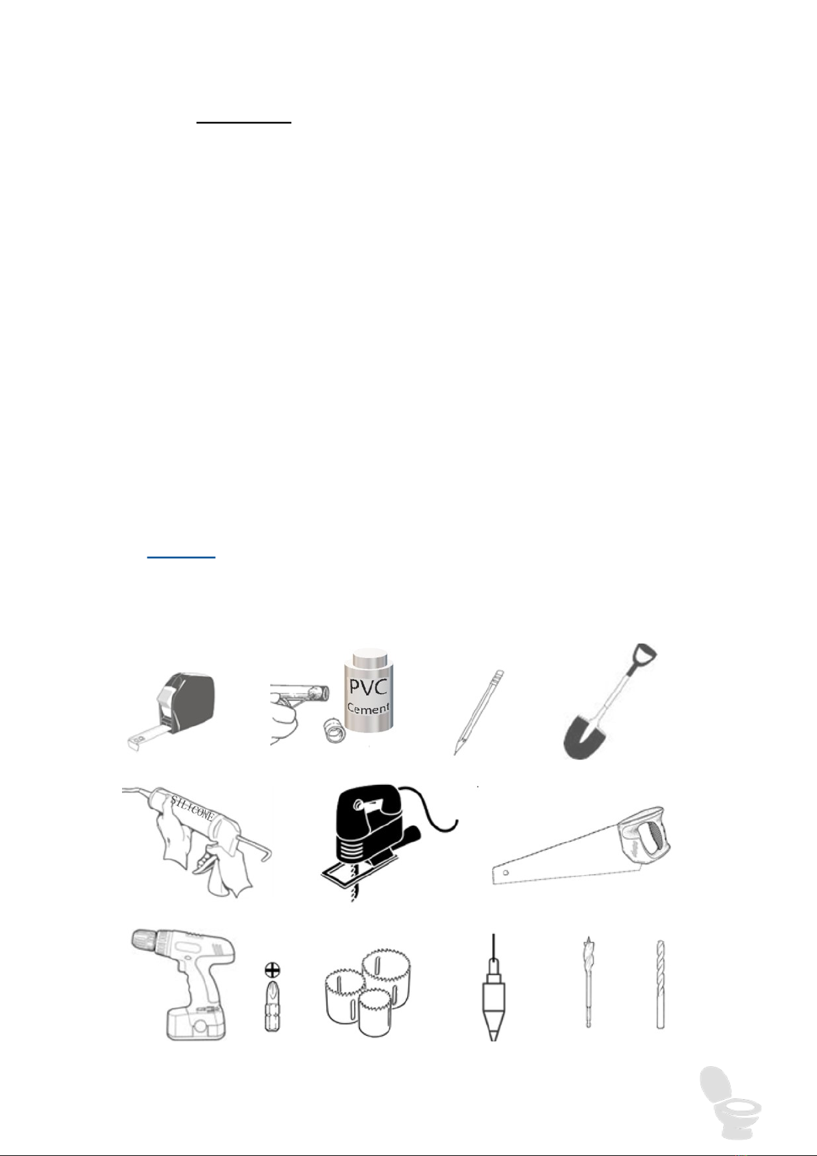
The following tools will be required to complete the installation:

IMNL-003.181008 © Ecoflo Wastewater Management Pty Ltd Page 5
TOILET INSTALLATION
STEP 1: Choose a suitable site to install the toilet.
The location of the toilet must have both:
Easy access to connect the fan system to a permanent vent pipe up the outside of the
structure. The vent pipe from the toilet exits horizontally through the wall behind the
toilet.
An elevated starting point for liquid to flow by gravity from the toilet down into a liquid
absorption trench which is to be dug outside the toilet room.
The toilet must also be located
close to a power source. E.g.
/

IMNL-003.181008 © Ecoflo Wastewater Management Pty Ltd Page 6
STEP 2: Installing the vent pipe & liquid drain
After selecting the toilet’s location, place the 50mm DWV PVC pipe through the 50mm Wal-
lace seal in the back of the pedestal. Push the pipe flush against the wall the toilet will back
onto (in the correct alignment). Use the PVC pipe to mark a circle on the wall as a guide.
Keeping the fibreglass bottom in the same position, put the 19mm liquid drain hose inside the
fibreglass bottom and push the end without the connector through the small hole at the rear of
the shell. Using this hose as a guide, mark a circle around the hose as close to the floor as
possible.
Using the circles drawn on the wall as a guide, cut a hole of sufficient size to allow the 50mm
DWV PVC pipe to push through the wall and a second hole (approximately 25mm) for the liq-
uid drain hose.
EcoFlo
IMNL-003.181008 © Ecoflo Wastewater Management Pty Ltd Page 7
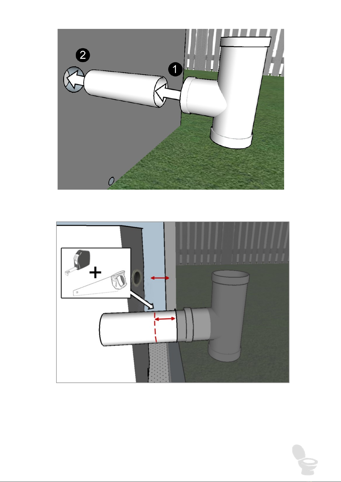
Push the 50mm PVC pipe length provided into the ‘T’ piece and then insert the 50mm PVC
pipe through the wall until the ‘T’ piece is flat against the wall.
Choose how far you would like the toilet to be from the wall and cut the 50mm DWV PVC
pipe to the corresponding length. Most people choose to locate the pedestal as close to the
wall as possible (remember to leave enough room for the pedestal lid to be removed when
changing chambers).
IMNL-003.181008 © Ecoflo Wastewater Management Pty Ltd Page 8
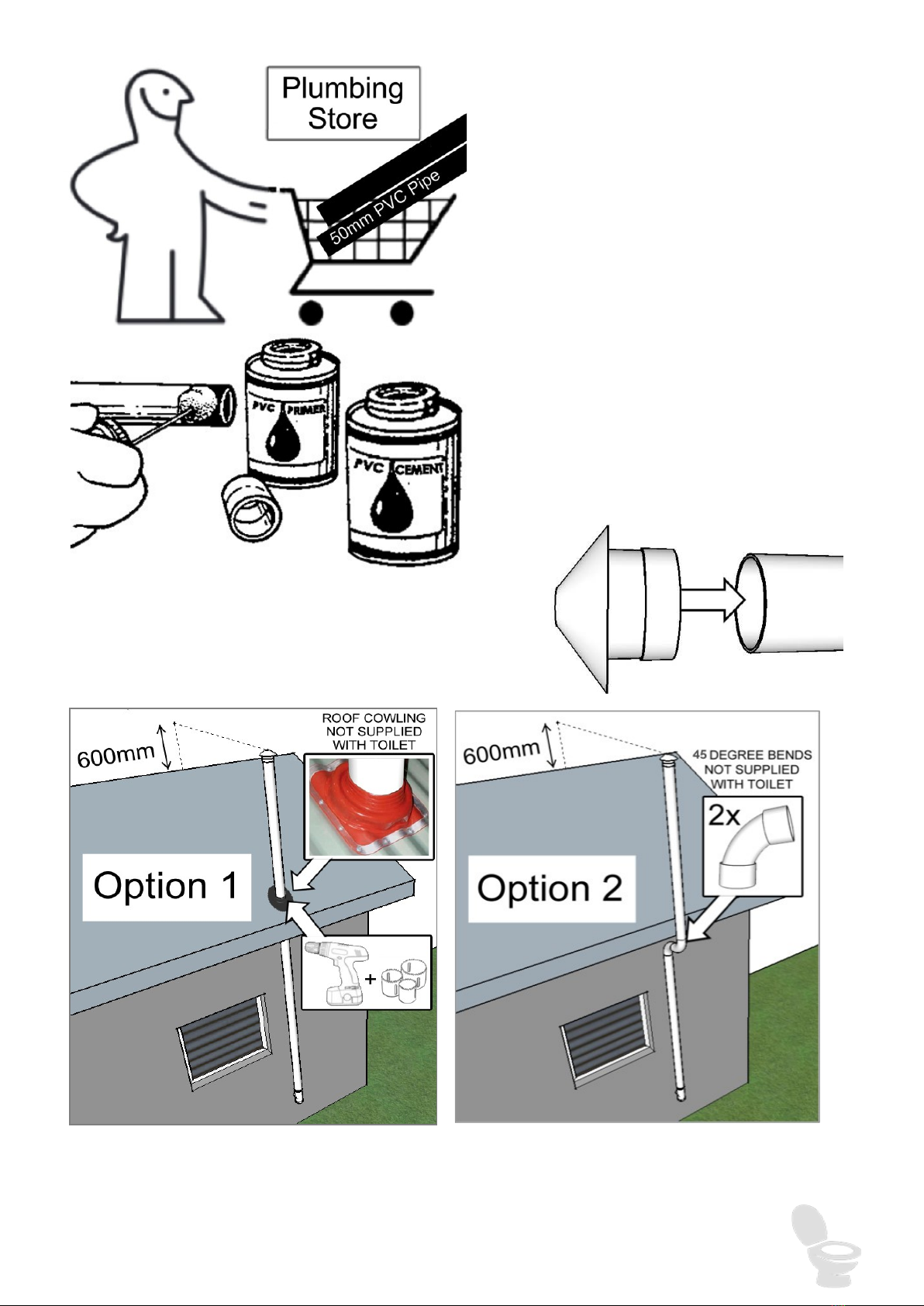
Purchase sufficient length(s) of 100mm
PVC vent pipe such that the vent will ex-
tend 600mm (2 feet) above the highest
point of the roof. Take the fan housing
provided to the plumbing store if you
aren’t sure which type to purchase.
All PVC pipe components, except all
components attached to the T piece
(including the fan housing) should be
glued together using Plumbers PVC
glue.
Con-
nect the provided 100mm vent cowl to the top of the
vent pipe, and then the bottom of the vent pipe into the
fan housing (do not glue this into the fan housing).
Install
the 100mm DWV PVC pipe as per Option 1 or Option 2 (pictured above). If possible, Op-
tion 1 is far better for ventilation as the two 45 degree elbows in Option 2 can slow the air
IMNL-003.181008 © Ecoflo Wastewater Management Pty Ltd Page 9
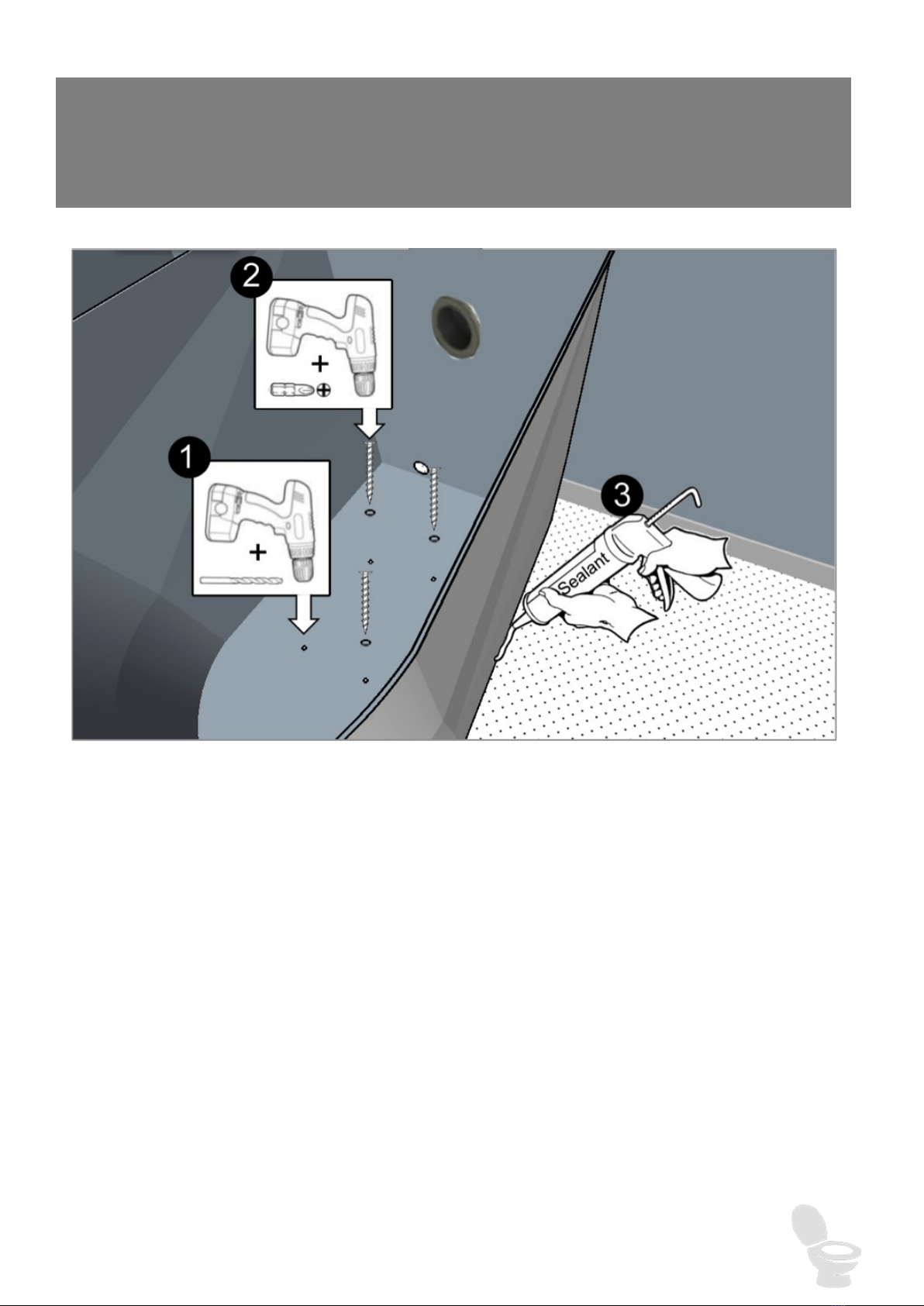
Once the toilet is permanently connected to the ‘T’ piece you may attach the fibreglass toilet
bottom to the floor with the self tapping screws and nylon washers (supplied) and / or an seal-
ant (not supplied).
The moisture trap is a 50 mm PVC ‘T” Junction with a small hole in the push-on
cap base. Any rain or condensation draining from the vent pipe will be trapped in
this junction instead of wetting the fan and shortening its life. The water drains
from the hole which needs to be cleaned regularly.

IMNL-003.181008 © Ecoflo Wastewater Management Pty Ltd Page 10
STEP 3: Constructing the liquid drain absorption trench
Place the plain end of the 19mm lilac liquid
drain hose through the small hole in the rear of
the fibreglass toilet shell. Feed the hose
through until the liquid drain valve connection
side is resting just on the inside of the shell
near the hole.
The hose exiting through the hole in the shell
should lead through the hole previously cut into
the bathroom wall and out towards the absorp-
tion trench.
Construct the excess liquid drain absorption
trench as per the following diagrams.
IMNL-003.181008 © Ecoflo Wastewater Management Pty Ltd Page 11
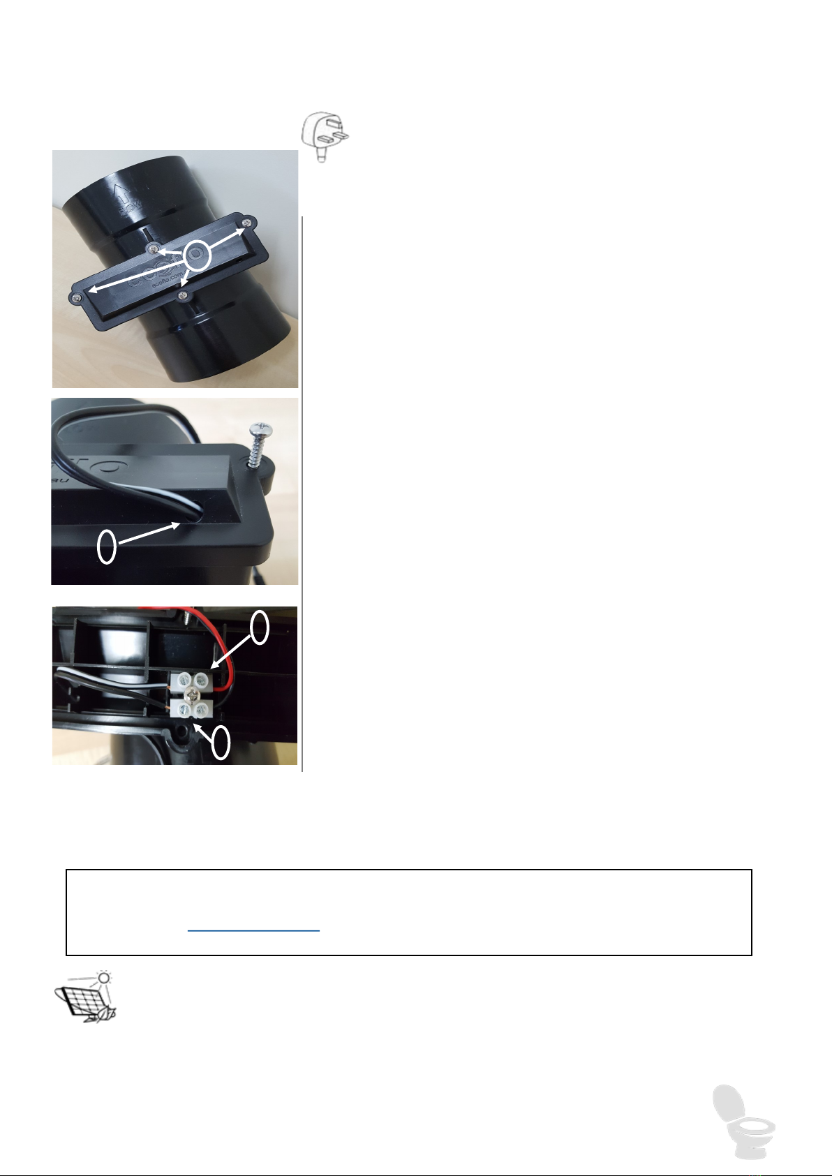
1. On the Fan Housing, remove the four screws from the
rectangular access cover and then carefully lift off
cover to expose wire connector.
2. Thread the Transformer wire through the hole in the
Cover.
3. Insert the Positive wire (white line); from the Trans-
former, in line with the Red Fan wire and tighten
screw to secure wire.
4. Insert the Negative wire (black line); from the
Transormer, in line with the Black Fan wire and tight-
en screw to secure wire.
5. Carefully replace the Cover; back on the Fan Housing
and tighten the four screws .
STEP 4: POWERING YOUR FAN
Mains Power
A 240/12 volt regulated transformer is included to run
the fan from mains power. Connect the fans to the
transformer as follows:
We recommend a spare fan is kept on hand at all times, particularly after a year of use.
Go to Ecoflo Online Store or call 1300 138 182 for replacement or spare fans.
Solar Power – refer to Solar Panel Installation Manual
1
3
2
4

IMNL-003.181008 © Ecoflo Wastewater Management Pty Ltd Page 12
Fan Warranty Information
With proper installation and care the fans will provide several years of relia-
ble service. However, experience has shown, improper installation may
result in the failure or greatly reduced life of this product.
Powering the fans by unregulated power sources such as some solar-
based systems or other sources in excess of a regulated 12 volts will re-
duce the life of these fans and may result in immediate failure. If you are
considering connection to a source other than a transformer or solar
panel as supplied by Ecoflo, you should read the warranty conditions
below.
Limited warranty conditions – 12-volt fan:
The 12-volt fans supplied with your Classic 850 come with a three-month
manufacturer’s warranty. Ecoflo triples the term of this warranty in addi-
tion to the manufacturer to 12 months from date of purchase and will
replace any fan that fails during the warranty period but only under
the following conditions:
The fan must be connected and powered by either a 12-volt transform-
er or solar panel supplied or otherwise recommended by Ecoflo. Con-
necting your fan directly to a power source other than one supplied or
specified by us may result in immediate damage to the fan and will void
all warranties.
The fan must be installed as specified in the owner’s manual supplied
with the toilet and must not be modified or altered in any way.
In the event of failure during the warranty period, the faulty fan must be
returned to Ecoflo who will ship a replacement by regular mail service
on the next business day providing the above conditions have been
met.
IMNL-003.181008 © Ecoflo Wastewater Management Pty Ltd Page 13
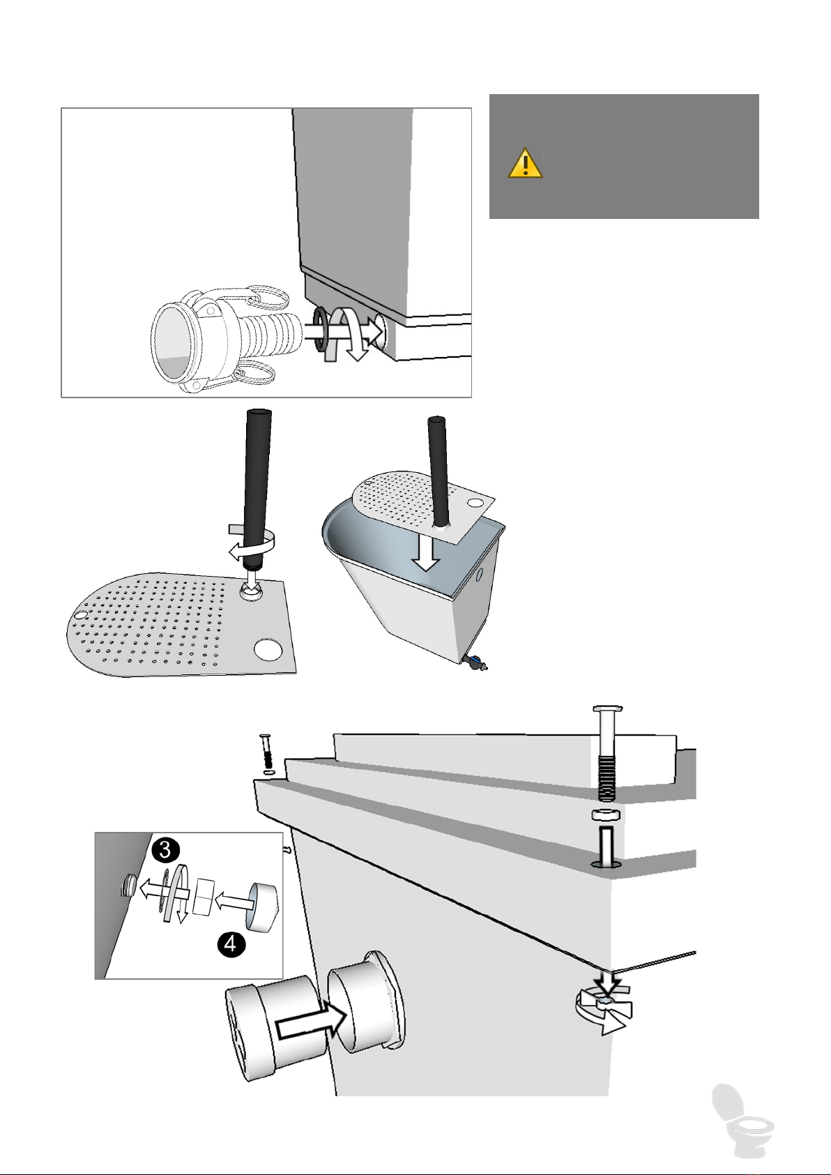
STEP 5: Assembling the compost chamber-
Screw the Cam-Lock into the flat side of
the compost chamber at the base with the
tap in the open position (pointing along
the direction the liquid will flow).
Screw in the 40mm black threaded
breather pipe into the raised thread-
ed hole. Make sure the pipe and
hole are well aligned when you start
turning. Tighten untill most of the
thread is in the hole (leave 5-10mm
showing). Place the false floor in-
side the chamber with the flat side
down.
IMPORTANT:
Do not glue any of the
compost chamber compo-
nents together.

IMNL-003.181008 © Ecoflo Wastewater Management Pty Ltd Page 14
Fit the 40mm rubber washer around the threaded part of the 40mm MI adaptor. Push this end through
the hole in the rear wall of the compost chamber. While holding the socket in place put the 40mm DWV
PVC pipe with the 90o elbow into the hole in the floor at the back of the chamber. Angle this pipe such
that the elbow is now aligned with the threaded end of the socket and screw these components together.
The socket and elbow should now be firm against the wall of the chamber and the pipe with the elbow
resting just below the false floor. Use a multitool wrench if you cannot tighten the socket sufficiently by
hand.
Once finished the compost chamber should look
like the picture above. Repeat for all remaining
chambers.
Excelet Chamber

IMNL-003.181008 © Ecoflo Wastewater Management Pty Ltd Page 15
Place the lid onto the chamber bottom and fasten in place with the bolt and wing nuts at the
back corner of the chamber. Remember, there will be one less chamber lid than compost
chamber bottoms (i.e. the ‘in-service’ chamber will not have a lid
whilst it is in-use).
For the ‘out-of-service’ chambers with lids, push the 40mm re-
movable breather cap (unthreaded) into the 40mm socket
screwed into the rear of the chamber. This completes the ‘out-of-
service’ arrangement which should prevent the entrance of in-
sects whilst allowing air to ciculate through the compost when
the chamber is composting outside.
Once assembled you can store these chambers wherever is con-
venient whilst the first chamber is in use. The chambers are
made from UV resistant plastic and come with a 10 year warranty.
1.Place the ‘in-service’ chamber (no
lid or 40mm breather cap) into the
base of the toilet shell.
2. connect the liquid drain valve at
the rear of the chamber to the liquid
drain hose.
Ensure the valve is open by turning it to be parallel with the direction of the drain hose. Push
the chamber as far forward as possible so the rim of the compost chamber is touching the front
of the fibreglass bottom.
As with every new compost chamber, layer the bottom of chamber with 25mm of bulking mate-
rial (coarse mulch that will not fall through the holes in the floor).
The shell top can now be placed onto the base. Do not glue the top to the base as it will need
to be removed from time to time to rotate the chambers.
If you have completed Steps 1-5 you
are now ready to use your toilet!
After 5 days add half a pack of Nature Quick microbes to the cham-
ber. Follow the instructions on the pack and use the other half in 2
weeks.
IMNL-003.181008 © Ecoflo Wastewater Management Pty Ltd Page 16
COMPOSTING ACCELERATORS
Whilst Nature Loo users report successful composting without the use of any additives, we
strongly recommend the use of the following in order to optimise composting, particularly when
the toilet is in permanent use by more than two people.
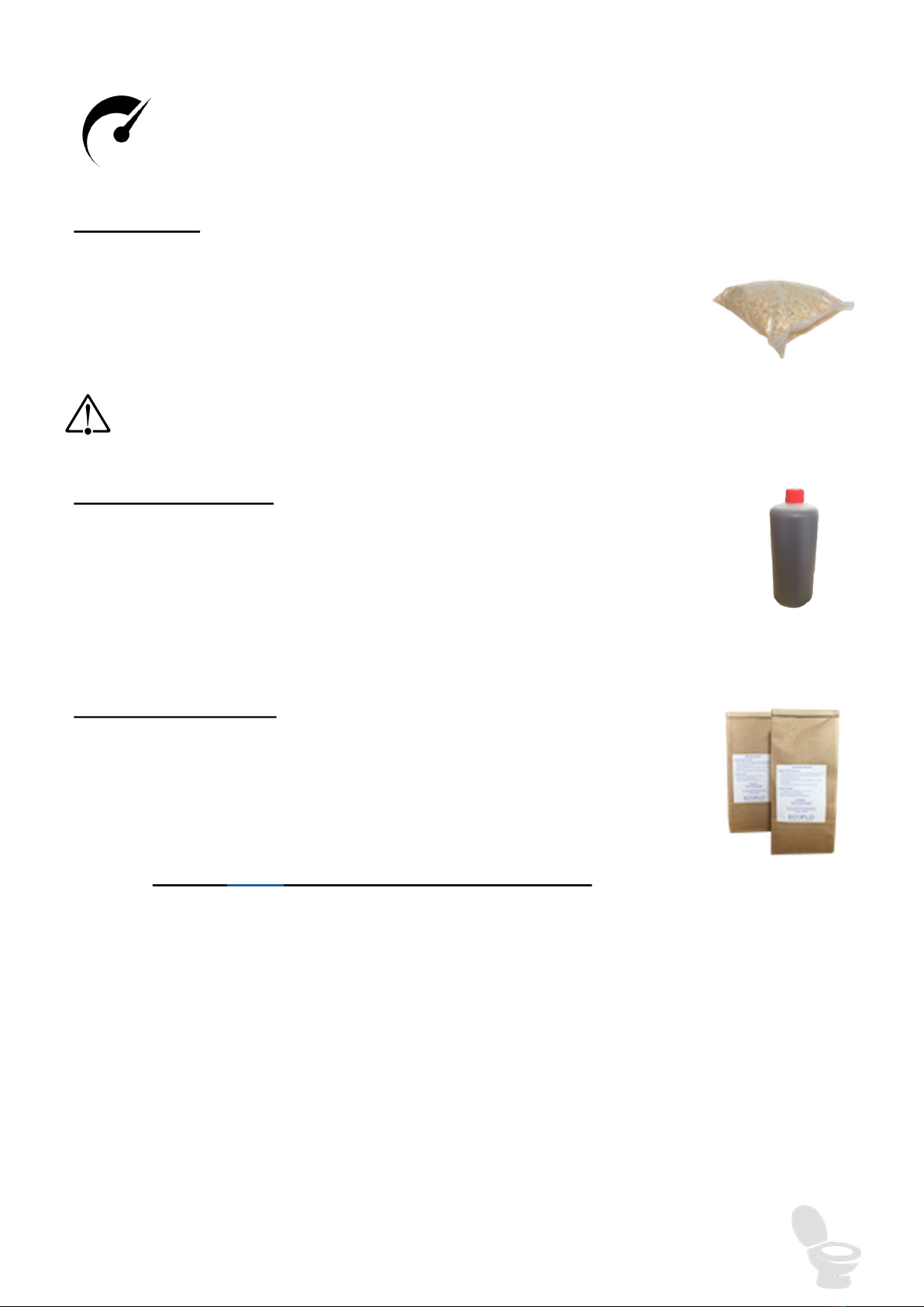
Bulking Agent
Should be added on a regular basis, preferably a handful after each solid
use. Alternatively, if this is not possible add the equivalent of this on a daily
or weekly basis. The bulking agent can be added through the pedestal.
Refer to our website for suitable bulking agents.
We Do Not recommend the use of :
• sawdust as it creates an anaerobic condition within the chamber.
• Cypress, cedar or eucalypt wood shavings due to their antimicrobial properties.
Nature Flush Enzymes
A 125ml bottle of enzyme concentrate is supplied with the toilet. Please
refer to the label for instructions and spray into the waste chute. A spray
flask is provided. Any staining of the pedestal can also be removed with
the spray.
Nature Quick Microbes
Should be used each time a chamber is changed to kick start the
process in the new chamber.
Contact Ecoflo for further supplies when required.

IMNL-003.181008 © Ecoflo Wastewater Management Pty Ltd Page 17
CARE & MAINTENANCE
Operating the Chamber Screen: The Excelet CS top comes with a movable screen to
obscure the view into the compost chamber. Follow these instructions to operate and
maintain the barrier.
Open the barrier before use by either lifting the entire seat or by sitting on the toilet.
To close the screen simply put the seat & lid down.
Use the Nature Flush enzyme spray and toilet paper should the screen require clean-
ing.
Maintain Correct Moisture: To compost effectively, the pile should be kept moist (see
‘the composting process’ – page 26). Assuming no urine enters the chamber add one
mug of water per person per week. This is an average; add less till the chamber is half
full. Add more in summer. Pour the water over the whole surface not just in one spot. If
too much water is added it will flood the bottom of the chamber and turn the system
anaerobic and maloderous. It is best to use diluted Nature Flush enzymes which accel-
erate composting and provide a pleasant fragrance to the toilet.
Foreign Objects: The system should not be used for the disposal of sanitary napkins,
disposable diapers or any other matter.
Cleaning the Shell and Seat: Just like any other toilet system, you will need to clean it
occasionally. To do so, use the Nature Flush enzymes as per the instructions on the
bottle with toilet paper. Soiled toilet paper can simply be dropped into the toilet.
Fan and Insect Screen: Every month check that the fan is turning freely and clean the
hole at the bottom of the moisture trap as well as the fly screen inside the trap.
IMNL-003.181008 © Ecoflo Wastewater Management Pty Ltd Page 18
EXCHANGING THE COMPOST CHAMBERS
The ‘In-Service’ compost chamber will need to be changed on a regular basis. The rate of fill-
ing will depend on the number of users. When the chamber becomes full, you will need to swap
it with a new or previously composted chamber by following these instructions.
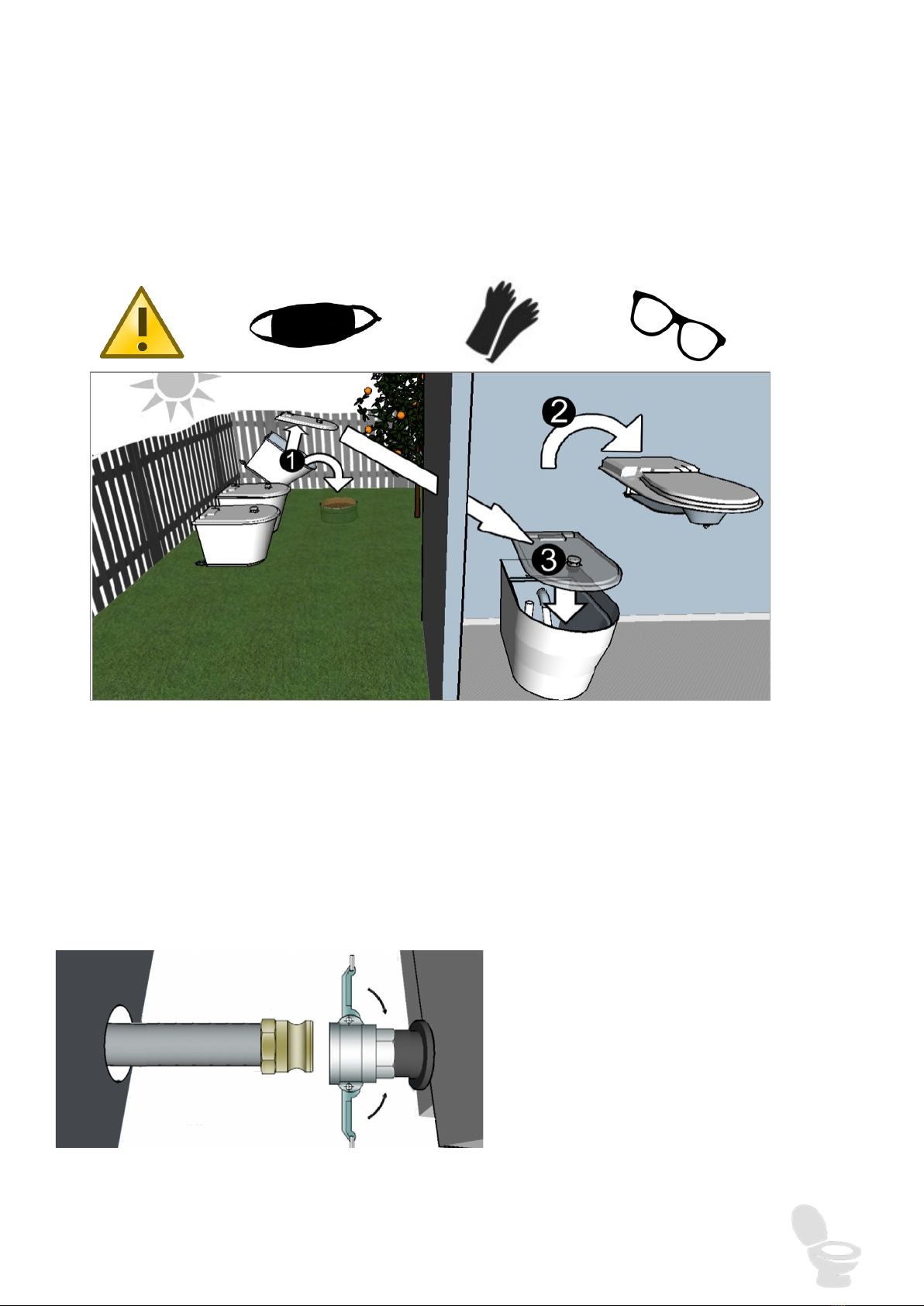
Please ensure you wear protective glasses, face mask & gloves.
1. ‘Identify the compost chamber that has been composting in the sun for the longest time.
Remove its lid by unscrewing the wing nuts and empty the compost into a hole (not within
100m of a potable water supply) on your property. Cover the top of the compost pile with
at least 100mm of soil or mulch. Alternatively, check with your local government if it would
allow you to mix the toilet compost with your general garden compost.
2. Put a couple of handfulls of bulking material into the In-Service chamber before removing
the fibreglass toilet top to access the full compost chamber.
3. Place an out-of-service lid firmly onto the full chamber & secure with wing nuts & bolts.
4. Release the Cam-lock levers & pull
out the hose.
5. Place Dust-Plug into Cam-Lock &
lock levers. Replace the full cham-
ber with empty one & connect the
hose to the Cam-lock on the latter.
IMNL-003.181008 © Ecoflo Wastewater Management Pty Ltd Page 19
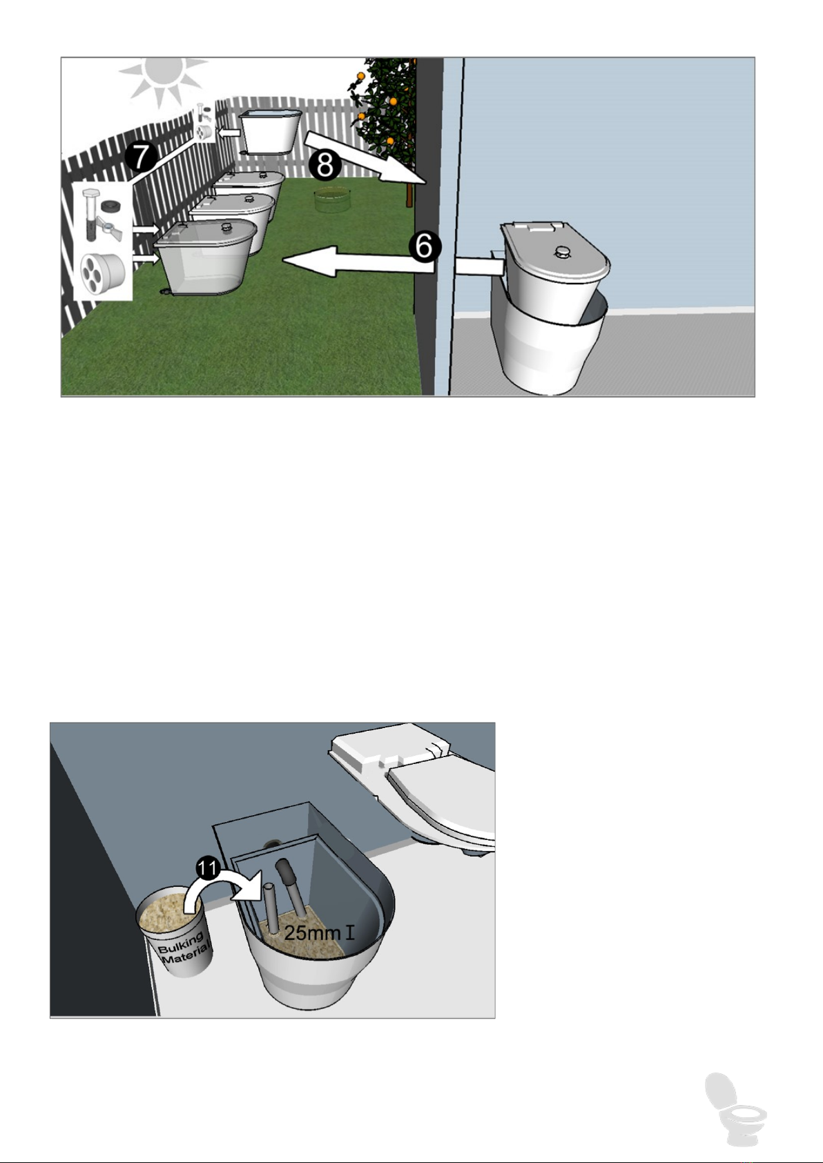
6. Place the full chamber outside in a sunny well vented position to speed up the break-
down process.
7. Insects or small animals may enter the chamber if you do not:
8. a. Fasten the lid to the full compost chamber using the bolt and wing nut from the
now empty compost chamber.
9. b. Take the 40mm breather cap from the 40mm socket in the rear of the now
empty chamber and push this into the rear of the full chamber.
10. Place the recently emptied compost chamber into the fibreglass toilet bottom. Before
proceeding to Steps 9 and 10 first check the liquid drain valve is clear of any block-
ages/debris.
11. Push the liquid drain valve into the hose
12. Open the valve by turning it parralel with the drain hose.
13. Add 25mm of bulking ma-
terial as bedding for the
empty chamber. To accel-
erate the composting pro-
cess add Nature Quick Mi-
crobes as per the instruc-
tions on the packaging or
several scoops of compost
from the hole after a cou-
ple days of using the toilet.

IMNL-003.181008 © Ecoflo Wastewater Management Pty Ltd Page 20
Nature Loo toilets have proven themselves to be one of the easiest systems to manage. However, being a
natural process, reliant on a number of factors beyond our control, it can occasionally need some help to
maintain an appropriate balance.
TROUBLE SHOOTING
Please read this section before using your toilet.
Find more Trouble Shooting and FAQ information online at ecoflo.com.au/FAQ, or call
us on 1300 138 182.
The ‘In-service’ chamber is filling too quickly:
This may be caused by a number of factors:
The temperature is too low for effective composting.
With the Classic 850 you can improve this problem by wrapping the chamber in insulating material (including the
base), OR use a chamber with a heating element option (page 9).
Insufficient air flow. ‘
This can be caused by a broken fan or the chamber being too full. Check the fan is operating and the
level of the pile is not too high. This problem could also be caused by a blocked insect screen in the
cowl.
The pile being too wet.
This could be the result of the outlet of the liquid chamber being blocked and causing the upper chamber
to flood. (This would also cause the fan to malfunction). Check the drain hose is not blocked and flush
with a hose if necessary. You may need to change chambers if the blockage is in the chamber and thor-
oughly flush out the contents of the liquid chamber.
Antibiotics and disinfectants will slow down or stop the process. Restart the composting by
reintroducing microorganisms. In many of these situations Nature Flush Enzymes will help
solve inefficient composting by breaking down the solids and thereby speeding up decomposi-
tion.
The ‘Out-of-service’ chamber is composting too slowly:
This may happen due to one or more of the problems described above. At this point the most effec-
tive course of action is to aerate the pile by turning it over with the Compost Mixer. You could also
add 500ml of Nature Flush Enzymes from a domestic spray bottle as you turn the material and add a
quantity of Nature Quick Microbes.
You should consider locating the chamber where it has a greater exposure to direct sun light. Howev-
er, if you find the pile is drying out too quickly put the chamber in a shadier position.
If you find none of the above measures are effective, it means the local climatic conditions are less
than ideal. This can happen in cold or humid conditions and you will need to purchase an additional
chamber in order to provide an extended composting period.
If you need to change your ‘In-service’ chamber and the ‘Out-of-service’ chamber is not yet compost-
ed dispose of the waste as normal and order a new chamber from Ecoflo.
If the ‘half-life’ is too great, we suggest ordering a chamber with a Heating Pad for the winter months.
Please consider the power requirements (12volt 100Watt 8.5Amps) when using the Heating Pad op-
tion off-grid.
This manual suits for next models
1
Table of contents
Other Ecoflo Toilet manuals


Popular Toilet manuals by other brands

Progetto
Progetto EVO EV105 Installation instructions & user manual

Kohler
Kohler Wellworth K-4468 manual

American Standard
American Standard Optum VorMax 707AA.101 owner's manual

Drive DeVilbiss Healthcare
Drive DeVilbiss Healthcare SOLO Toilet Lift manual

Bradley
Bradley MG Series Installation

Inax
Inax AC-902VN Assembly


Kohler
Kohler Revival K-3360 Homeowner's guide

Bischoff & Bischoff
Bischoff & Bischoff TS-Care instruction manual

American Standard
American Standard VorMax Plus 708AA Series owner's manual

Royal Line
Royal Line Onedrous Digital Bidet TH-0111 quick guide

nella
nella SWIFT NBMU-3312 installation instructions

URIMAT
URIMAT Trespa 35.001 Installation instruction