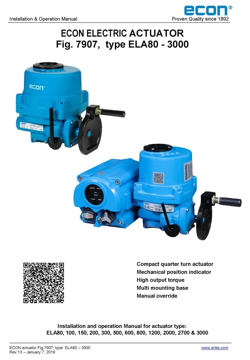
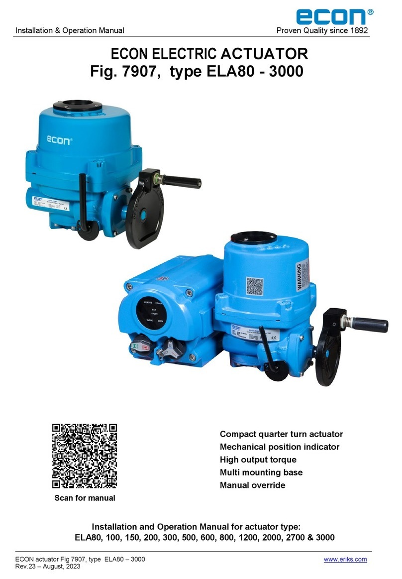
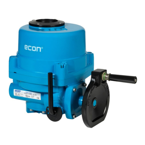
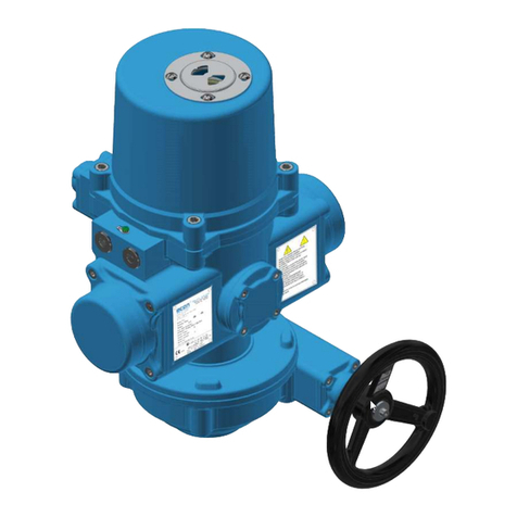
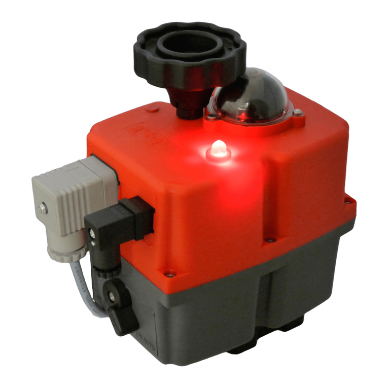
Econ Fig. 21401 User manual

Installation & Operation Manual Proven Quality since 1892
ECON Hydraulic Actuator Fig.21401-21402 www.eriks.com
Rev.0 –April, 2020
ECON HYDRAULIC LINEAR ACTUATOR
Fig. 21401 Spring Return
Actuator, type ESL
Fig. 21402
Double Acting
Actuator
, type EDL
Installation & Operation Manual for Hydraulic Actuator:
Fig. 21401, 21402

Installation & Operation Manual Proven Quality since 1892
ECON Hydraulic Actuator Fig.21401-21402 www.eriks.com
Rev.0 –April, 2020 1
Contents
1. INTRODUCTION 2
1.1 Purpose 2
1.2 Safety notices 2
2. PRODUCT IDENTIFICATION 3
2.1 Product
Identification 3
2.1.1 Marking 3
2.1.2 Certification 3
2.2 Initial Inspection 3
2.3 Storage 3
3. GENERAL INFORMATION AND FEATURES 4
3.1 General Information 4
3.1.1 Standard Technical Data 4
3.1.2 Actuator versions 4
3.2 External Parts for Double & Single acting actuator 5
3.3 Globe Valve mounting 5
4. INSTALLATION & HYDRAULIC REQUIREMENTS 6
4.1 Pre-installation 6
4.1.1 Actuator application 6
4.1.2 Actuator orientation 6
4.1.3 Actuator installation 6
4.2 Recommended Oil Quality 7
4.2.1 Hydraulic System flushing 7
5. OPERATION 8
5.1 General Operation 8
5.1.1 Double Acting actuator 8
5.1.2 Single Acting actuator 8
5.2 Manual (emergency) operation 8
6. ACTUATOR DIMENSIONS 9
7. SPARE PARTS 11
7.1 ESL/EDL Hydraulic Actuator 11
8. MAINTENANCE 12
8.1 Visual Check 12
8.2 Inspection of the oil 12
8.3 Inspection of the spring housing and disc springs (ESL) 12
9. TROUBLESHOOTING 13

Installation & Operation Manual Proven Quality since 1892
ECON Hydraulic Actuator Fig.21401-21402 www.eriks.com
Rev.0 –April, 2020 2
1 INTRODUCTION
1.1 Purpose
The purpose of this manual is to introduce and explain the installation, operation and maintenance of the
ESL / EDL Hydraulic Linear Actuators.
1.2 Safety Notices
This manual contains safety notices and precautions the user must take to reduce the risk of personal
injury and damage to the equipment. The user(s) must read these instructions before the installation,
operation or maintenance of the ESL / EDL Hydraulic Linear Actuators.
DANGER: Refers to personal safety and alerts the user for danger and/or injury.
Hazardous or unsafe practice may result in severe injury or death.
WARNING: Refers to personal safety. Alerts the user for potential danger.
Not following warning notices could result in personal injury or death.
CAUTION: Directs the user’s attention to general precautions that,
if not followed, could result in personal injury and/or equipment
damage.
Note: Information in this manual is critical to the user’s understanding of the actuator’s installation
and operation.

Installation & Operation Manual Proven Quality since 1892
ECON Hydraulic Actuator Fig.21401-21402 www.eriks.com
Rev.0 –April, 2020 3
2 PRODUCT IDENTIFICATION
2.1 Product Identification
The product name plate is located on top of the connection flange. The name plate contains the
following:
2.1.1 Marking
•ECON logo (trademark)
•Figure number
•Serial number
•Actuator type
•Standard Hydraulic working pressure
2.1.2 Certification
LRS Type Approval Certificate
2.2 Initial Inspection
Upon the receipt of the actuator, the user should inspect the condition of the product and ensure
that the product specification stated on the name plate matches with the order sheet.
•Remove the packing wrap or wooden box carefully. Inspect the product for any physical
damage that may have occurred during shipment.
•Check the product specification of the received product. If a wrong product has been
supplied, please immediately report this to the distributing company.
2.3 Storage
Actuators must be stored in a clean, cool and dry area. The unit should be stored with the top cover
installed and the connection ports plugged. Storage must be off the floor, covered with a sealed dust
protector.

Installation & Operation Manual Proven Quality since 1892
ECON Hydraulic Actuator Fig.21401-21402 www.eriks.com
Rev.0 –April, 2020 4
3 GENERAL INFORMATION AND FEATURES
3.1 General Information
ECON Linear actuators are equipped with a standardised connecting flange for direct mounting of
Hydraulic Accessories and with ¼ inch threaded connection ports for BSP Hydraulic couplers.
•Fig. 21401 –Single acting Hydraulic actuator
•Fig. 21402 –Double acting Hydraulic actuator
3.1.1 Standard Technical Data
Standard working pressure 135 bar
Test pressure 240 bar
Force output 3150 N up to 17550 N
Valve connection Eriks standard, based on Mounting set
Indication Standard visual indicator for open/closed position indication, optional limit switches available
Local Control Minimess quick connection couplers, type SMK20 M16x2
Hydraulic connections ¼ inch BSP
Ambient Temperature
-20°C (-4°F) up to +80°C (176°F)
External Coating Acryl 2K AC (Lechler), RAL5015
3.1.2 Actuator Versions
Fig. 21402
Double acting
Nominal force
in Newton
Maximum stroke
in mm
Displacement
in cc (max. stroke)
Weight
in KG
EDL-1
6075
40
23
7
EDL-2
17550
80
138
15
EDL-3
on request
on request
on request
on request
EDL-4
on request
on request
on request
on request
Fig. 21401
Single acting
Hydraulic opening
force in Newton
Spring closing force
in Newton
Maximum stroke
in mm
Displacement
in cc (max. stroke)
Weight
in KG
ESL-1
3150
2925
35
20
18
ESL-2
9100
8450
53
88
40
ESR-3
on request
on request
on request
on request
on request
ESR-4
on request
on request
on request
on request
on request

Installation & Operation Manual Proven Quality since 1892
ECON Hydraulic Actuator Fig.21401-21402 www.eriks.com
Rev.0 –April, 2020 5
3.2 External Parts for Double & Single acting actuator
3.3 Globe Valve mounting
Position Item delivery
1 Actuator bottom flange actuator
2 O-Ring mounting set
3 Valve mounting flange (bonnet) mounting set
4 Gasket mounting set
5 Valve spindle mounting set
6 Valve globe valve

Installation & Operation Manual Proven Quality since 1892
ECON Hydraulic Actuator Fig.21401-21402 www.eriks.com
Rev.0 –April, 2020 6
4 INSTALLATION & HYDRAULIC REQUIREMENTS
4.1 Pre-installation
Note: Prior to mounting, actuator assembly must be checked for any damage.
Damaged parts must be replaced by original spare parts.
Verify the actuator’s nameplate to ensure that actuator type, model number, force output are correct
before installation or use.
Check if the hydraulic control pressure corresponds with your system specification and the information on
the actuator type plate.
4.1.1 Actuator application
ECON hydraulic actuators are used for operation of Globe valves and Valve Chests. The actuators are
designed for severe operating conditions. For use in extreme conditions e.g. aggressive, corrosive
environments it is recommended to mention this at the ordering stage, in order to verify if the actuator is
suitable. The installation designer is responsible for the hydraulic actuator selection and must determine
if the actuator is suitable for the working conditions.
ECON hydraulic actuators are also available for submerged application up to 50 mt depth.
For submerged application a shaft cover should always be placed on top of the actuator to avoid water
from penetrating the assembly through the actuator shaft.
4.1.2 Actuator orientation
The actuator can be installed in any position on to the valve, however it can be that the complete valve
assembly is not allowed to be mounted in vertical position because of valve specifics. Check the valve
specifications before installing.
When the actuator has an Electric Hydraulic Powerpack there can also be restrictions in installing the
assembly. Check the Powerpack specifications before installing.
4.1.3 Actuator Installation
The handling and transportation of actuators must be carried out with extreme precaution and using the
necessary and adequate means depending on their size and weight in order to avoid risks to the
operators handling them.
All ESL/EDL actuators will be delivered in combination with a globe valve or valve chest. This because of
specialized mounting and adjusting procedure of the valve.
Actuators should be installed in such a way that they are easy to access in order to do the periodic
inspections and corresponding maintenance operations necessary to guarantee the performance qualities
that they have been designed for.

Installation & Operation Manual Proven Quality since 1892
ECON Hydraulic Actuator Fig.21401-21402 www.eriks.com
Rev.0 –April, 2020 7
4.2 Recommended Oil Quality
The use of clean oil increases the lifetime of the actuators, as well as the lifetime of their accessories,
solenoids and other hydraulic accessories
Any type of mineral oil can be used, the HLP type (DIN 51524-2) is recommended.
Also many fire-resistant fluids (as HFC) or polyglycole can be used.
Viscosity Range: 15 ¸ 200 mm2/sec (Oil ISO VG 46 mm2/sec DIN 51519 is recommended)
4.2.1 Hydraulic System flushing
The actuators are supplied cleaned and plugged; before to start up, the connection piping and the
hydraulic system have to be flushed according to ISO 4406 16/13 (NAS 1638/7) or better.

Installation & Operation Manual Proven Quality since 1892
ECON Hydraulic Actuator Fig.21401-21402 www.eriks.com
Rev.0 –April, 2020 8
5 OPERATION
5.1 General Operation
The ESL/EDL standard connection flange includes two hydraulic ports, threaded for 1/4“ BSP couplings.
When hydraulic pressure is supplied to these ports the piston moves and slides through the housing
The actuator piston connects to the valve spindle and when operated results into an opening or closing
of the valve.
5.1.1 Double Acting actuator
When oil is supplied to port A the actuator piston will make a downwards movement(closing), when oil is
supplied to port B it will make upwards movement (opening).
5.1.2 Single Acting actuator
On a single acting actuator the opening movement is done by hydraulic pressure and the closing
movement is done by a spring.
The spring in ESL single acting actuators is of a mechanical type, the spring housing contains a set of
disc springs, whenever a spring breaks the remaining springs take over and the valve is kept close with
a slightly lower force.
5.2 Manual (emergency) operation
Besides operation through the main system, the actuator can also be operated through a handpump.
Each actuator is equipped with two Handpump connectors. In order to use these connectors, the actuator
must be isolated from the main system through pilot control valves, a ball valve, or a solenoid valve with
a closed (mid) position.
- Double acting actuators have two type QC3 connectors
- Single acting actuators have one type QC3 for pressure side and a smaller type QC5 for spring side.
Operation is the same as described before; the connector on the side of port A will close the valve,
when the connector on the side of port B will open the valve.
The QC5 connector on a single acting actuator is only used when the spring is defect.

Installation & Operation Manual Proven Quality since 1892
ECON Hydraulic Actuator Fig.21401-21402 www.eriks.com
Rev.0 –April, 2020 12
8 MAINTENANCE
WARNING:
Turn off all power before performing maintenance on the actuator.
POTENTIALLY HIGH-PRESSURE VESSEL. Before removing or
disassembling, ensure that the actuator or other actuated device is
isolated and not under pressure.
The hydraulic linear actuators do not require periodic maintenance operations, but only of a visual
check, and verification of the oil.
8.1 Visual check
Check list:
- Screws are tight
- Quick couplings are tight and closed with its cap
- Electrical (switch) box (if present) is correctly connected, screws tightened and the cable connected
- No external leakage of Hydraulic oil
8.2 Inspection of the oil
The oil in the system must be checked after about 1000 valve maneuvers but at least every 5 years.
The oil must be clear and of the same transparency and color as new oil
The oil must be HLP DIN 51524-2, standard viscosity class VG 46mm2/sec DIN 51519.
A spot oil test is suggested after 5 years: no sludge and oil contamination are tolerated by the
system. The oil cleanness must be according NAS 3801 class 9.
8.3 Inspection of the spring housing and disc springs (ESL)
The top lid of the ESL actuator is under tension because of the springs, take extreme caution!
Before opening the top of the actuator, replace the mounting bolts for long bolts with nuts or use a
(hydraulic) press to release the tension on the springs.
When using long bolts; screw in the bolts one at a time, place a washer and fasten the nut against the lid.
After all bolts have been installed loosen the nuts a couple of rotations each time in a crosswise pattern till
the tension on the lid is gone.
When using a hydraulic press; place the actuator in between the hydraulic press without putting too much
force on the top lid. Support the actuator, loosen the mounting bolts of the lid and release the tension by
unloading the press.

Installation & Operation Manual Proven Quality since 1892
ECON Hydraulic Actuator Fig.21401-21402 www.eriks.com
Rev.0 –April, 2020 13
9 TROUBLESHOOTING
The main issues on this hydraulic actuator and the right actions are schematized in below trouble shooting
table. The table helps the operator to detect the problem and how to solve it.
►Double acting actuator does not open or close
Check; Control pressure on the handpump connectors of the actuator
A pressure of between 100-135bar should be present to operate the actuator when installed on a valve.
- If a normal control pressure is present check if the valve is not blocked
- If the valve is not blocked check for external oil leakage on the actuator
►Single acting actuator does not open
Check; Control pressure on the (open side) handpump connector of the actuator
A pressure of between 100-135bar should be present to open the actuator when installed on a valve.
- If a normal control pressure is present check if the valve is not blocked
- If the valve is not blocked check for external oil leakage on the actuator
Check; if oil is trapped on the spring side of the actuator
Remove the handpump connector on the gas spring side and operate the actuator.
►Single acting actuator does not close
Check; if the valve is not blocked
- Inspection of the spring housing on broken disc springs.
- Check for external oil leakage on the actuator

Installation & Operation Manual Proven Quality since 1892
ECON Hydraulic Actuator Fig.21501-21502 www.eriks.com
Rev.0 –April, 2020 14
If you have questions about this product,
Please contact the nearest ECON distributor.
You can find them on www.eriks.com
ERIKS Flow Control
Cypresbaan 63,
2908 LT Capelle aan den IJssel,
The Netherlands
Phone: +31 (0)88 855 8100
This manual suits for next models
1
Table of contents
Other Econ Controllers manuals
Popular Controllers manuals by other brands

Ransburg
Ransburg DynaFlow A12233 Service instruction

Evco
Evco Vcolor 579 Installer manual
Honeywell
Honeywell Lyric LCP300-LC User reference guide

Klockner Moeller
Klockner Moeller PS 416-TCS-200 Hardware and engineering

Danfoss
Danfoss AK-CC55 installation guide

Crestron
Crestron INET-IOEX-IRCOM installation guide


