manuals.online logo
Brands
  1. Home
  2. •
  3. Brands
  4. •
  5. Crestron
  6. •
  7. Controllers
  8. •
  9. Crestron INET-IOEX-IRCOM User manual

Crestron INET-IOEX-IRCOM User manual

INET-IOEX-IRCOM
inNET EX®Control Module
Installation Guide
Hardware Hookup
Make the necessary connections as called out in the
following illustration.
When making connections to the INET-IOEX-IRCOM,
use Crestron power supplies for Crestron equipment.
Description
The Crestron®INET-IOEX-IRCOM control module
provides an IR and RS-232 control interface for video
displays, AV components, small appliances, and other
equipment. The control module includes two discrete IR
ports and one bidirectional RS-232 port.
The control module communicates with a Crestron
3-Series®control system via the inNET EX®wireless
network, allowing for control and monitoring of remote
devices without running wiring or installing conduit.
NOTE: The INET-IOEX-IRCOM is compatible only
with Crestron 3-Series control systems.
Installation
The INET-IOEX-IRCOM may be mounted onto any at
surface using three mounting screws (not included).
For best results, install the device in an location where it
will not receive interference from nearby RF sources,
obstructions, and metal surfaces.
Additional Resources
Visit the product page on the
Crestron website (www.crestron.com)
for additional information and the
latest rmware updates. Use a QR
reader application on your mobile
device to scan the QR image.
G/TX/RX:
To any
RS-232 device
S/G (1–2):
To IR
devices
PWR:
From power
pack
Wireless Communications
The INET-IOEX-IRCOM must be acquired by an
inNET EX wireless gateway or by a control system with
a built-in inNET EX gateway (both not included) before
it may be used with a 3-Series control system.
Use the procedures below to join or leave an inNET EX
network and to verify communications between the
device and the control system.
NOTE: The INET-IOEX-IRCOM may be acquired only
by one network.
Join the inNET EX Network
1. Press the ACQUIRE button on the inNET EX
gateway to enter Acquire mode, or enter Acquire
mode from Crestron Toolbox™ software.
NOTE: In an environment where there are
multiple gateways installed, place only one
gateway in Acquire mode at a time.
2. Press the SETUP button three times, and then
press and hold the button down
(press-press-press-press+hold) until the LED on
the device ashes once. This process may take
up to ten seconds to complete.
NOTE: If the INET-IOEX-IRCOM was previously
acquired to another gateway, press the SETUP
button three times, and then press and hold the
button down (press-press-press-press+hold) for
over ten seconds.
3. Release the button to start the acquire process.
The LED ashes slowly to show that the device is
actively scanning the inNET EX network.
Mounting
screws (3)
INET-IOEX-IRCOM
4. Conrm the status of the acquire process:
• If the INET-IOEX-IRCOM is acquired by the inNET EX network, the LED lights for ve seconds.
• If the INET-IOEX-IRCOM is not acquired by the inNET EX network, The LED ashes rapidly for several
seconds. Press the SETUP button to cancel the acquire process. Ensure the gateway is in Acquire mode and
that the INET-IOEX-IRCOM is in range before attempting the acquire process again.
5. After the process is complete, remove the gateway from Acquire mode as described by its documentation.
Leave the inNET EX Network
1. Verify that the INET-IOEX-IRCOM is not within range of a gateway that is in Acquire mode.
2. Press the SETUP button three times, and then press and hold the button down (press-press-press-press+hold)
until the LED on the device ashes once. This process may take up to ten seconds to complete.
3. Release the button. The LED ashes quickly to indicate that the INET-IOEX-IRCOM has left the inNET EX
wireless network.
4. Press the SETUP button to acknowledge that the device has left the network and to stop the ashing LED.
Verify the Communications Status
To check the communications status of the INET-IOEX-IRCOM, press the SETUP button three times, and then press
and hold the button down (press-press-press-press+hold) for up to two seconds. The LED blinks to indicate the
communications status as described in the table below.
As of the date of manufacture, the product has been tested
and found to comply with specications for CE marking.
Federal Communications Commission (FCC) Compliance
Statement
This device complies with part 15 of the FCC Rules.
Operation is subject to the following conditions: (1) This
device may not cause harmful interference and (2) this device
must accept any interference received, including interference
that may cause undesired operation.
CAUTION: Changes or modications not expressly approved
by the manufacturer responsible for compliance could void
the user’s authority to operate the equipment.
NOTE: This equipment has been tested and found to comply
with the limits for a Class B digital device, pursuant to part 15
of the FCC Rules. These limits are designed to provide
reasonable protection against harmful interference in a
residential installation. This equipment generates, uses and
can radiate radio frequency energy and, if not installed and
used in accordance with the instructions, may cause harmful
interference to radio communications. However, there is no
guarantee that interference will not occur in a particular
installation. If this equipment does cause harmful interference
to radio or television reception, which can be determined by
turning the equipment off and on, the user is encouraged to
try to correct the interference by one or more of the following
measures:
• Reorient or relocate the receiving antenna.
• Increase the separation between the equipment and
receiver.
• Connect the equipment into an outlet on a circuit
different from that to which the receiver is connected.
• Consult the dealer or an experienced radio/TV
technician for help.
Industry Canada (IC) Compliance Statement
CAN ICES-3 (B)/NMB-3(B)
RF Exposure (OET Bulletin 65):
To comply with FCC’s RF exposure limits for general
population/uncontrolled exposure, this transmitter must be
installed to provide a separation distance of at least 20 cm
from all persons and must not be colocated or operating in
conjunction with any other antenna or transmitter.
Product warranty can be found at
www.crestron.com/legal/sales-terms-conditions-warranties.
The specic patents that cover Crestron products are listed at
www.crestron.com/legal/patents.
Certain Crestron products contain open source software. For
specic information, please visit
www.crestron.com/legal/open-source-software.
Crestron, the Crestron logo, 3-Series, Crestron Toolbox, and
inNET EX are either trademarks or registered trademarks of
Crestron Electronics, Inc. in the United States and/or other
countries. Other trademarks, registered trademarks, and trade
names may be used in this document to refer to either the
entities claiming the marks and names or their products.
Crestron disclaims any proprietary interest in the marks and
names of others. Crestron is not responsible for errors in
typography or photography.
This document was written by the Technical Publications
department at Crestron.
©2018 Crestron Electronics, Inc.
Crestron Electronics, Inc. Installation Guide
15 Volvo Drive DOC. 7476F
Rockleigh, NJ 07647 (2035851)
Tel: 888.CRESTRON 06.18
Fax: 201.767.7576 Specications subject to
www.crestron.com change without notice.
LED COMMUNICATIONS STATUS
The LED turns on for ve
seconds
The device is communicating with the control system.
The LED blinks three times. The device is communicating with the gateway, but the gateway is not
communicating with the control system.
The LED blinks twice. The device was previously joined to the network but is not communicating with
the gateway.
The LED blinks once. The device is not joined to the network.
Other Crestron Controllers manuals

Crestron CGDMX-512BI How to use

Crestron

Crestron CGDMX-512BI How to use

Crestron SP-SC User manual

Crestron

Crestron SP-SC User manual

Crestron CLS-EXP-DIMFLV User manual

Crestron

Crestron CLS-EXP-DIMFLV User manual

Crestron DM-RMC-4K-100-C-1G User manual

Crestron

Crestron DM-RMC-4K-100-C-1G User manual

Crestron infiNET HTT-B10X User manual

Crestron

Crestron infiNET HTT-B10X User manual

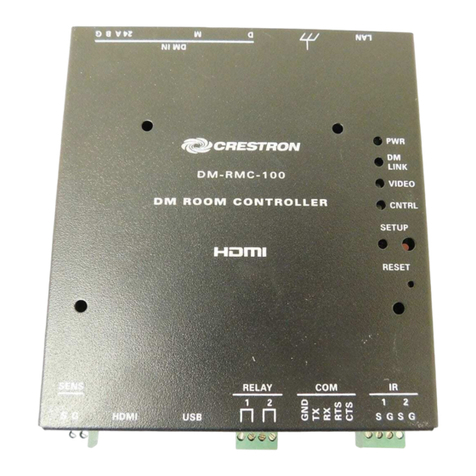
Crestron DigitalMedia Room Controller DM-RMC-100 How to use

Crestron

Crestron DigitalMedia Room Controller DM-RMC-100 How to use

Crestron DigitalMedia 8G+ DM-RMC-200-C Dimensional drawing

Crestron

Crestron DigitalMedia 8G+ DM-RMC-200-C Dimensional drawing

Crestron 4K DigitalMedia 3-Series User manual

Crestron

Crestron 4K DigitalMedia 3-Series User manual

Crestron DigitalMedia 8G DM-RMC-200-S Dimensional drawing

Crestron

Crestron DigitalMedia 8G DM-RMC-200-S Dimensional drawing

Crestron PC-350V-12 User manual

Crestron

Crestron PC-350V-12 User manual

Crestron onCue BPC-8 Owner's manual

Crestron

Crestron onCue BPC-8 Owner's manual

Crestron CN-TVAV User manual

Crestron

Crestron CN-TVAV User manual

Crestron ST-VC User manual

Crestron

Crestron ST-VC User manual

Crestron 4 Series User manual

Crestron

Crestron 4 Series User manual

Crestron MPC-M10 Installation and operating instructions

Crestron

Crestron MPC-M10 Installation and operating instructions

Crestron onCue BPC-8 User manual

Crestron

Crestron onCue BPC-8 User manual

Crestron CP4-R User manual

Crestron

Crestron CP4-R User manual

Crestron CP3-R User manual

Crestron

Crestron CP3-R User manual

Crestron onCue BPC-8 Dimensional drawing

Crestron

Crestron onCue BPC-8 Dimensional drawing

Crestron C2N-SSC-2 How to use

Crestron

Crestron C2N-SSC-2 How to use

Crestron CNXFZ User manual

Crestron

Crestron CNXFZ User manual

Crestron MC2W User manual

Crestron

Crestron MC2W User manual

Crestron ZUMMESH-JBOX Series User manual

Crestron

Crestron ZUMMESH-JBOX Series User manual

Crestron ZUMMESH-JBOX-DALI User manual

Crestron

Crestron ZUMMESH-JBOX-DALI User manual

Popular Controllers manuals by other brands

Philips TDA8002C datasheet

Philips

Philips TDA8002C datasheet

Endress+Hauser Liquiline CM442 operating instructions

Endress+Hauser

Endress+Hauser Liquiline CM442 operating instructions

Tengri Remote Cockpit Setup guide

Tengri

Tengri Remote Cockpit Setup guide

S&P REB-1N manual

S&P

S&P REB-1N manual

Grundfos VGA-113 Installation and operating instructions

Grundfos

Grundfos VGA-113 Installation and operating instructions

PowerBox Systems voltage regulator instruction manual

PowerBox Systems

PowerBox Systems voltage regulator instruction manual

AUTLED LC-012-004 user manual

AUTLED

AUTLED LC-012-004 user manual

Toshiba APOGEE FLN APG001Z Installation & operation

Toshiba

Toshiba APOGEE FLN APG001Z Installation & operation

LINK-MI LM-TV09P user manual

LINK-MI

LINK-MI LM-TV09P user manual

DH Instruments REGULATOR KIT ONTO 1-4 IN. MOLSTIC-S instruction sheet

DH Instruments

DH Instruments REGULATOR KIT ONTO 1-4 IN. MOLSTIC-S instruction sheet

HydroAir 20-0312 quick start guide

HydroAir

HydroAir 20-0312 quick start guide

CNC4PC PLASMA THC-3 user manual

CNC4PC

CNC4PC PLASMA THC-3 user manual

ABB ACS800-17 Hardware manual

ABB

ABB ACS800-17 Hardware manual

Savant SmartControl 25 Quick reference guide

Savant

Savant SmartControl 25 Quick reference guide

Sorel MTDC Installation and operating instructions

Sorel

Sorel MTDC Installation and operating instructions

ASAHI YUKIZAI Dymatrix AVBPR user manual

ASAHI YUKIZAI

ASAHI YUKIZAI Dymatrix AVBPR user manual

Afag KLF 5 Original operating instructions

Afag

Afag KLF 5 Original operating instructions

THORLABS LDC200C series quick reference

THORLABS

THORLABS LDC200C series quick reference

manuals.online logo
manuals.online logoBrands
  • About & Mission
  • Contact us
  • Privacy Policy
  • Terms and Conditions

Copyright 2025 Manuals.Online. All Rights Reserved.