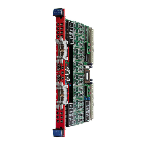
Caen V1495 Technical document

Technical
Information
Manual
MOD. V1495
12 February 2010
Revision n. 8
GENERAL PURPOSE
VME BOARD
NPO:
00117/04:V1495.MUTx/08

CAEN will repair or replace any product within the guarantee period if the Guarantor declares that the
product is defective due to workmanship or materials and has not been caused by mishandling,
negligence on behalf of the User, accident or any abnormal conditions or operations.
CAEN declines all responsibility for damages or
injuries caused by an improper use of the Modules due
to negligence on behalf of the User. It is strongly
recommended to read thoroughly the CAEN User's
Manual before any kind of operation.
CAEN reserves the right to change partially or entirely the contents of this Manual at any time
and without giving any notice.
Disposal of the Product
The product must never be dumped in the Municipal Waste. Please check your local
regulations for disposal of electronics products.

Document type: Title: Revision date: Revision:
User's Manual (MUT) Mod. V1495 General Purpose VME Board 12/02/2010 8
NPO: Filename: Number of pages: Page:
00117/04:V1495.MUTx/08 V1495_REV8.DOC 42 3
TABLE OF CONTENTS
1. GENERAL DESCRIPTION.........................................................................................................................6
1.1. OVERVIEW ...............................................................................................................................................6
1.2. BLOCK DIAGRAM.....................................................................................................................................7
2. TECHNICAL SPECIFICATIONS..............................................................................................................8
2.1. PACKAGING..............................................................................................................................................8
2.2. POWER REQUIREMENTS ............................................................................................................................8
2.3. FRONT PANEL DISPLAYS ...........................................................................................................................8
2.4. FRONT PANEL...........................................................................................................................................9
2.5. MOTHERBOARD SPECIFICATIONS ...........................................................................................................10
2.6. MEZZANINE SPECIFICATIONS .................................................................................................................10
2.7. MEZZANINE BOARDS INSTALLATION ......................................................................................................11
2.8. FRONT PANEL CONNECTOR CABLING......................................................................................................11
3. OPERATING MODES...............................................................................................................................13
3.1. TIMERS...................................................................................................................................................13
3.1.1. Timer0, Timer1..............................................................................................................................13
3.1.2. Timer2, Timer3..............................................................................................................................14
3.2. FPGA PROGRAMMING ...........................................................................................................................15
3.2.1. FPGA VME....................................................................................................................................15
3.2.2. FPGA USER..................................................................................................................................16
4. VME INTERFACE.....................................................................................................................................17
4.1. REGISTER ADDRESS MAP ........................................................................................................................17
4.1.1. Configuration ROM.......................................................................................................................17
4.2. CONTROL REGISTER...............................................................................................................................18
4.3. STATUS REGISTER..................................................................................................................................18
4.4. INTERRUPT LEVEL REGISTER .................................................................................................................18
4.5. INTERRUPT STATUS-ID REGISTER..........................................................................................................19
4.6. GEO ADDRESS REGISTER ......................................................................................................................19
4.7. MODULE RESET REGISTER .....................................................................................................................19
4.8. FIRMWARE REVISION REGISTER.............................................................................................................19
4.9. SCRATCH16 REGISTER ...........................................................................................................................20
4.10. SCRATCH32 REGISTER .......................................................................................................................20
4.11. SELECT VME FPGA FLASH REGISTER...............................................................................................20
4.12. SELECT USER FPGA FLASH REGISTER .............................................................................................20
4.13. VME FPGA FLASH MEMORY ............................................................................................................20

Document type: Title: Revision date: Revision:
User's Manual (MUT) Mod. V1495 General Purpose VME Board 12/02/2010 8
NPO: Filename: Number of pages: Page:
00117/04:V1495.MUTx/08 V1495_REV8.DOC 42 4
4.14. USER FPGA FLASH MEMORY...........................................................................................................20
4.15. USER FPGA CONFIGURATION REGISTER..........................................................................................21
5. V1495 USER FPGA REFERENCE DESIGN KIT...................................................................................22
5.1. INTRODUCTION.......................................................................................................................................22
5.2. DESIGN KIT............................................................................................................................................22
5.2.1. V1495HAL.....................................................................................................................................22
5.2.2. COIN_REFERENCE Design.........................................................................................................23
5.3. INTERFACE DESCRIPTION........................................................................................................................25
5.3.1. Global Signals...............................................................................................................................25
5.3.2. REGISTER INTERFACE...............................................................................................................25
5.3.3. V1495 Front Panel Ports (PORT A,B,C,G) INTERFACE.............................................................26
5.3.4. V1495 Mezzanine Expansion Ports (PORT D,E,F) INTERFACE.................................................26
5.3.5. PDL Configuration Interface.........................................................................................................26
5.3.6. Delay Lines and Oscillators I/O....................................................................................................27
5.3.7. SPARE Interface............................................................................................................................27
5.3.8. LED Interface................................................................................................................................27
5.4. REFERENCE DESIGN DESCRIPTION ..........................................................................................................27
5.5. REGISTER DETAILED DESCRIPTION.............................................................................................31
5.5.1. V1495 Front Panel Ports Registers (PORT A,B,C,G)...................................................................31
5.5.2. V1495 Mezzanine Expansion Ports Registers (PORT D,E,F).......................................................32
5.5.3. Delay Selection..............................................................................................................................32
5.5.4. PDL DELAY VALUE SETTING AND READBACK......................................................................33
5.5.5. Delay Unit using PDLs..................................................................................................................34
5.5.6. Delay Unit using DLOs .................................................................................................................35
5.6. QUARTUS II WEB EDITION PROJECT ......................................................................................................36
5.7. FIRMWARE UPGRADE..............................................................................................................................42
LIST OF FIGURES
FIG.1.1: MOD.V1495 BLOCK DIAGRAM .................................................................................................................7
FIG.2.1: MODEL V1495 FRONT PANEL (WITH A395A/B/C PIGGY BACK BOARDS) ...................................................9
FIG.2.2: MULTIPIN CONNECTOR PIN ASSIGNMENT .................................................................................................11
FIG.2.3: MOD.A967 CABLE ADAPTER .................................................................................................................12
FIG.3.1: TIMERS DIAGRAM ....................................................................................................................................14
FIG.3.2: GATE PULSE EXAMPLE .............................................................................................................................14
FIG.3.3: TIMER2AND TIMER3USED TOGETHER FOR HANDLING A GATE PULSE.....................................................15
FIG.3.4: FPGA VME DIAGRAM.............................................................................................................................15
FIG.3.5: FPGA USER DIAGRAM............................................................................................................................16
FIG.4.1: INTERRUPT LEVEL REGISTER...................................................................................................................18
FIG.4.2: INTERRUPT VECTOR REGISTER ................................................................................................................19
FIG.4.3: GEOGRAPHICAL ADDRESS REGISTER ........................................................................................................19
FIG.4.4: FIRMWARE REVISION REGISTER ..............................................................................................................19

Document type: Title: Revision date: Revision:
User's Manual (MUT) Mod. V1495 General Purpose VME Board 12/02/2010 8
NPO: Filename: Number of pages: Page:
00117/04:V1495.MUTx/08 V1495_REV8.DOC 42 5
FIG.4.5: USER FPGA CONFIGURATION REGISTER................................................................................................21
FIG.5.1: USER FPGA BLOCK DIAGRAM................................................................................................................22
FIG.5.2: FRONT PANEL PORTS INTERFACE DIAGRAM............................................................................................28
FIG.5.3: PDL_CONTROL BIT FIELDS...................................................................................................................33
FIG.5.4: DELAY UNIT WITH PDLS.........................................................................................................................34
FIG.5.5: PDLS DELAY LINE TIMING.......................................................................................................................34
FIG.5.6: DELAY UNIT WITH DLOS........................................................................................................................36
FIG.5.7: DLOS DELAY LINE TIMING ......................................................................................................................36
FIG.5.8: QUARTUS II PROJECT FLOW......................................................................................................................37
FIG.5.9: QUARTUS II MAIN MENU ..........................................................................................................................38
FIG.5.10: QUARTUS II FILE MENU..........................................................................................................................38
FIG.5.11: QUARTUS II PROJECT BROWSER .............................................................................................................39
FIG.5.12: QUARTUS II NETLIST..............................................................................................................................40
FIG.5.13: QUARTUS II HIERARCHICAL STRUCTURE................................................................................................40
FIG.5.14: QUARTUS II COMPILER LAUNCHING .......................................................................................................41
FIG.5.15: QUARTUS II COMPILING SUMMARY........................................................................................................41
LIST OF TABLES
TABLE 1.1: AVAILABLE ITEMS .................................................................................................................................6
TABLE 2.1: MODEL V1495 AND MEZZANINE BOARDS POWER REQUIREMENTS.........................................................8
TABLE 2.2: V1495 MOTHERBOARD I/O SECTIONS..................................................................................................10
TABLE 2.3: V1495 MEZZANINE BOARDS................................................................................................................10
TABLE 4.1: ADDRESS MAP FOR THE MODEL V1495...............................................................................................17
TABLE 4.2: ROM ADDRESS MAP FOR THE MODEL V1495.....................................................................................17
TABLE 5.1: COIN_REFERENCE SIGNALS............................................................................................................23
TABLE 5.2: V1495 MEZZANINE EXPANSION PORTS SIGNALS.................................................................................26
TABLE 5.3: PDL CONFIGURATION INTERFACE SIGNALS.........................................................................................26
TABLE 5.4: DELAY LINES AND OSCILLATORS SIGNALS ..........................................................................................27
TABLE 5.5: SPARE INTERFACE SIGNALS ...............................................................................................................27
TABLE 5.6: LED INTERFACE SIGNALS....................................................................................................................27
TABLE 5.7: COIN_REFERENCE REGISTER MAP ..................................................................................................29
TABLE 5.8: SELECTION OF THE DELAY LINE ...........................................................................................................32

Document type: Title: Revision date: Revision:
User's Manual (MUT) Mod. V1495 General Purpose VME Board 12/02/2010 8
NPO: Filename: Number of pages: Page:
00117/04:V1495.MUTx/08 V1495_REV8.DOC 42 6
1.General description
1.1. Overview
The Mod. V1495 is a VME 6U board, 1U wide, suitable for various digital
Gate/Trigger/Translate/Buffer/Test applications, which can be directly customised by the
User, and whose management is handled by two FPGA’s:
FPGA “Bridge”, which is used for the VME interface and for the connection between the
VME interface and the 2nd FPGA (FPGA “User”) through a proprietary local bus. FPGA
“Bridge” manages also the programming via VME of the FPGA “User”.
FPGA “User”, which manages the front panel I/O channels. FPGA “User” is provided with
a basic firmware which allows to perform coincidence matrix, I/O register and
asynchronous timers functions.
FPGA “User” can be also free reprogrammed by the user with own custom logic function
(see § 5.1). It is connected as slave to the FPGA “Bridge” via CAEN Local Bus, whose
protocol shall be used in order to communicate with the FPGA “Bridge” and thus with the
VME bus.
The I/O channel digital interface is composed by four sections (A, B, C, G) placed on the
motherboard (see § 1.2). The channel interface can be expanded in the D, E, F sections
by using up to 3 mezzanine boards (see § 2.6 and § 2.7), which can be added, choosing
between the five types developed in order to cover the I/O functions and the ECL, PECL,
LVDS, NIM, TTL signals and 16bit DAC (see § 1.2). The maximum number of channels
can be expanded up to 194.
The FPGA “User” can be programmed “on the fly” directly via VME, without external
hardware tools, without disconnecting the board from the set up, without resetting it or
turning the crate off, allowing quick debug operations by the developer with his own
firmware. A flash memory on the board can store the different programming file, which
can be loaded to the FPGA “User” at any moment.
Four independent digital programmable asynchronous timers are available for
Gate/Trigger applications. It is possible to chain them for generating complex
Gate/Trigger pulse.
Table 1.1: Available items
Code Description
WV1495XAAAAA V1495 - General Purpose VME Board
WA395XAAAAAA A395A - 32 LVDS/ECL/PECL input channels
WA395XBAAAAA A395B - 32 LVDS output channels
WA395XCAAAAA A395C - 32 ECL output channels
WA395XDAAAAA A395D - 8 NIM/TTL input/output channels
WA395XEAAAAA A395E - 8 channel 16Bit ±5V DAC
WPERS0149501 V1495 - Customization - 3 A395C Mounting Option
WA967XAAAAAA A967 - 32 Channel Cable Adapter (1x32 to 2x16)
WFW1495SCXAA FW1495SC - 128 Channels Latching Scaler for V1495

Document type: Title: Revision date: Revision:
User's Manual (MUT) Mod. V1495 General Purpose VME Board 12/02/2010 8
NPO: Filename: Number of pages: Page:
00117/04:V1495.MUTx/08 V1495_REV8.DOC 42 7
1.2. Block Diagram
Fig. 1.1: Mod. V1495 Block Diagram
A
B
C
32
32
32
32
32
32
USER
PROGRAMMABLE
FPGA
4
4
BRIDGE
FPGA
(VME interface)
16 bit
VME BUS
FLASH
µC
USER
FPGA
CONFIG
LOCAL
BUS 16/32/64 bit
G
(optional)
LPT
8 bit
FW LOADING
Asyn. Timers
D
E
F

Document type: Title: Revision date: Revision:
User's Manual (MUT) Mod. V1495 General Purpose VME Board 12/02/2010 8
NPO: Filename: Number of pages: Page:
00117/04:V1495.MUTx/08 V1495_REV8.DOC 42 8
2.Technical specifications
2.1. Packaging
The module is housed in a 6U-high, 1U-wide VME unit. The board is provided the VME
P1, and P2 connectors and fits into both VME standard and V430 backplanes.
2.2. Power requirements
The power requirements of the modules are as follows:
Table 2.1: Model V1495 and mezzanine boards power requirements
Power supply V1495 A395A A395B A395C A395D A395E
+5 V 1 A 0.1 A 0.1 A 1.4 A 1.1 A 0.3 A
2.3. Front panel displays
The front panel (refer to § 2.4) hosts the following LEDs:
DTACK: Colour: green.
Function: it lights up green whenever a VME read/write
access to the board is performed.
USER: Colour: green / orange / red.
Function: programmable.

Document type: Title: Revision date: Revision:
User's Manual (MUT) Mod. V1495 General Purpose VME Board 12/02/2010 8
NPO: Filename: Number of pages: Page:
00117/04:V1495.MUTx/08 V1495_REV8.DOC 42 9
2.4. Front Panel
SCALE
R
16
CH
Mod.
V560E
Mod. V1495
DTACK
AD
BA
GENERAL
PURPOSE
VME BOARD
0
O
U
T
0
31
31 --
--+
+
++
CF
USER
BE
L
V
D
S
/
E
C
L
0
31 --+
+
G0
L
V
D
S
G1
I
N
L
V
D
S
/
E
C
L
I
N
Fig. 2.1: Model V1495 front panel (with A395A/B/C piggy back boards)

Document type: Title: Revision date: Revision:
User's Manual (MUT) Mod. V1495 General Purpose VME Board 12/02/2010 8
NPO: Filename: Number of pages: Page:
00117/04:V1495.MUTx/08 V1495_REV8.DOC 42 10
2.5. Motherboard Specifications
The Mod. V1495 Motherboard is composed by four I/O sections (see § 1.2), described in
the following table:
Table 2.2: V1495 Motherboard I/O sections
Board No. of Ch. Direction Logic Signal Bandwidth Front panel connector
A/B 32 Input Direct
LVDS/ECL/PECL
(single ended
TTL optional)
110ohm Rt.
Extended
Common Mode
input range –4V
to +5V; Fail Safe
input feature.
200MHz
Robinson Nugent P50E-
068-P1-SR1-TG type,
(34+34) pins
C32 Output Direct LVDS
100ohm Rl 250MHz
Robinson Nugent P50E-
068-P1-SR1-TG type,
(34+34) pins
G2 I/O
selectable
TTL IN=Direct
TTL OUT=Direct
NIM IN=Invert
NIM OUT=Direct
NIM/TTL
selectable
Open/50ohm Rt
selectable
250MHz LEMO 00
2.6. Mezzanine Specifications
The five I/O Mezzanine boards developed so far are described in the following table:
Table 2.3: V1495 Mezzanine boards
Board No. of Ch. Direction Logic Signal Bandwidth Front panel connector
A395A 32 Input Direct
LVDS/ECL/
PECL
(single ended
TTL optional)
110ohm Rt.
Extended
Common Mode
input range –4V
to +5V; Fail
Safe input
feature.
200MHz
Robinson Nugent P50E-
068-P1-SR1-TG type,
(34+34) pins
A395B 32 Output Direct LVDS
100ohm Rl 250MHz
Robinson Nugent P50E-
068-P1-SR1-TG type,
(34+34) pins
A395C 32 Output Direct ECL 300MHz
Robinson Nugent P50E-
068-P1-SR1-TG type,
(34+34) pins
A395D 8 I/O
selectable
TTL IN=Direct
TTL OUT=Direct
NIM IN=Invert
NIM OUT=Direct
NIM/TTL
selectable
Open/50ohm Rt
selectable
250MHz LEMO 00
A395E 8 Output Analog
16bit resolution
±5V @10kΩRL
±4V @200ΩRL
N.A. LEMO 00

Document type: Title: Revision date: Revision:
User's Manual (MUT) Mod. V1495 General Purpose VME Board 12/02/2010 8
NPO: Filename: Number of pages: Page:
00117/04:V1495.MUTx/08 V1495_REV8.DOC 42 11
2.7. Mezzanine boards installation
In order to install one A395x-series mezzanine board on the V1495 motherboard it is
necessary to follow these steps:
−Remove (unscrew) the metal cover (one at will)
−Plug the mezzanine board into the 100 pin connector on the motherboard
−Fix the mezzanine board with the screws
WARNING! A Mounting Option is necessary in order to install three A395C
mezzanine boards on the V1495 (see table 1.1)
2.8. Front panel connector cabling
Motherboard I/O sections A, B, C and A395A, A395B and A395C Mezzanine boards
feature the Robinson Nugent P50E-068-P1-SR1-TG multipin connector, whose pin set is
shown in the following figure:
CH0+
CH0-
CH1+
CH1-
CH16+
CH16-
CH17+
CH17-
CH14+
CH14-
CH15+
CH15-
CH30+
CH30-
CH31+
CH31-
N.C.
N.C.
N.C.
N.C.
Fig. 2.2: Multipin connector pin assignment

Document type: Title: Revision date: Revision:
User's Manual (MUT) Mod. V1495 General Purpose VME Board 12/02/2010 8
NPO: Filename: Number of pages: Page:
00117/04:V1495.MUTx/08 V1495_REV8.DOC 42 12
The CAEN Mod. A967 Cable Adapter allows to adapt each Robinson Nugent Multipin
Connector into two 1” 17+17-pin Header-type male connectors (3M, 4634-7301) with
locks through two 25 cm long flat cables.
CH0
CH1
CH15
N.C.
CH16
CH17
CH31
N.C.
Fig. 2.3: Mod. A967 Cable Adapter

Document type: Title: Revision date: Revision:
User's Manual (MUT) Mod. V1495 General Purpose VME Board 12/02/2010 8
NPO: Filename: Number of pages: Page:
00117/04:V1495.MUTx/08 V1495_REV8.DOC 42 13
3.Operating modes
3.1. Timers
Gate/Trigger applications require the production of an output signal with programmable
width (Gate), whenever an input signal (Trigger) occurs.
Gates can be produced in several ways, according to the system set up, which can be
either synchronous or asynchronous.
Synchronous systems:
Input signals are referred to a system clock: they can be sampled by the clock itself and
the output is a gate signal (obtained with a counter) whose width (and delay) is a multiple
of the clock period. If the application requires a width (and delay) of the Gate signal
synchronous but with step resolution higher than the system clock period, this can be
achieved by enabling the PLL in the USER FPGA and enter the reference clock on
channel G0.
Asynchronous systems:
Input signals are not referred to a system clock. As a consequence the gate signal will be
generated without any time reference. It is possible to use the implementation described
above, with the freedom of choosing the clock source between external or 40MHz
internal. The resulting Gate signal will have stable duration, but with maximum position
jitter equal to one clock period.
Such position jitter can be rejected by using the asynchronous timers present on the
V1495, which allow to generate references synchronous with the occurred trigger.
3.1.1. Timer0, Timer1
Each timer is based on a programmable delay line. FPGA USER drives a STARTx pulse
and, after the programmed delay, it receives the return signal PULSEx. The time
difference between transmission and reception (logic implementation inside the FPGA
USER) can be used to drive a gate signal. The programming of the delay time can be
done manually as binary value either via 8 bit dip switches (SW4 and SW5) or via VME
register, with a 1ns step resolution (max step delay = 255ns). The software setting has
higher priority with respect to the dip switches.
The following figure shows a diagram of the timers usage:

Document type: Title: Revision date: Revision:
User's Manual (MUT) Mod. V1495 General Purpose VME Board 12/02/2010 8
NPO: Filename: Number of pages: Page:
00117/04:V1495.MUTx/08 V1495_REV8.DOC 42 14
Fig. 3.1: Timers diagram
The use of STARTx signals with timing shorter than those recommended is possible,
although the linearity on the set delay scale is no longer guaranteed.
3.1.2. Timer2, Timer3
Each timer is made up of one digital circuit which produces a typical fixed time base with
10ns period and 50% duty cycle. These timers are proposed for generating any Gate
pulse > 10ns with a 10ns step. The following figure shows an example of a Gate
generation made with Timer2 and n.3 PULSE width.
Fig. 3.2: Gate pulse example
FPGA USER drives a /STARTx pulse and after TEN time FPGA USER will receive a
PULSEx clock signal. A counter with clock = PULSEx implemented in the FPGA USER,
allows to generate a pulse with programmable duration. It is possible to reduce to one
half (5ns) the counter step by advancing the counter on both sides of PULSEx. Since the
circuit is completely digital, no recovery time is necessary between one stop and the
following start: it is thus possible to generate multiple gate pulses with very high rate.
Timer2 and Timer3 can be used together for handling one single Gate pulse from
multiple overlapped triggers.
enT
PULSE 2
/START 2
GATE
Tpd
COUNT 2 COUNT 0 COUNT 1 COUNT 2
T
Tperiod
width
offset
T
Tset
PULSE 0
START 0
GATE
Tdly= Toffset + Tset
Toffset = 30 ± 2ns
Tset = SETBINARY * 1ns
STARTx-WIDTHMIN = 320ns recommended (22ns absolute min.)
STARTx-PERIODMIN = 640ns recommended (46ns absolute min.)

Document type: Title: Revision date: Revision:
User's Manual (MUT) Mod. V1495 General Purpose VME Board 12/02/2010 8
NPO: Filename: Number of pages: Page:
00117/04:V1495.MUTx/08 V1495_REV8.DOC 42 15
Fig. 3.3: Timer2 and Timer3 used together for handling a Gate pulse
3.2. FPGA Programming
The programming of FPGA VME and FPGA USER are handled by two independent
microcontrollers + flash memory. The updating of the firmware contained in the flash
memories does not require the use of external tools and can be executed via VME.
The flash related to FPGA VME contains the firmware dedicated to the interface of the
board with the FPGA USER and the VME bus; such firmware is developed by CAEN.
The flash related to the FPGA USER contains the firmware developed by the User
according to his own application requirements.
3.2.1. FPGA VME
The microcontroller provides the firmware uploading at board’s power on. The flash
memory contains two versions of the firmware, which can be selected manually via
jumper (Standard or Backup).
Fig. 3.4: FPGA VME diagram
PULSE 2
/START 2
COUNT 2 COUNT 0 COUNT 1 COUNT 2
PULSE 3
/START 3
COUNT 3
GATE
COUNT 0 COUNT 1 COUNT 2
VME
FPGA
VME BUS
FLASH
uC
FPGA VME Program Circuit
STD
BKP
FW SEL

Document type: Title: Revision date: Revision:
User's Manual (MUT) Mod. V1495 General Purpose VME Board 12/02/2010 8
NPO: Filename: Number of pages: Page:
00117/04:V1495.MUTx/08 V1495_REV8.DOC 42 16
3.2.2. FPGA USER
The microcontroller provides the firmware uploading at board’s power on. The flash
memory contains one firmware image only (Standard).
Fig. 3.5: FPGA USER diagram
FPGA VME aim is to handle the operation of FPGA USER, which can be programmed on
the fly, i.e. without turning off the system, thus allowing quick debug operations by the
Developer.
Register implemented on FPGA VME allows the following operations:
•FPGA USER flash memory programming.
•FPGA USER updating.
FPGA
VME
VME BUS
FLASH
uC
FW LOAD
FW SEL
FPGA
USER
FPGA USER Program Circuit

Document type: Title: Revision date: Revision:
User's Manual (MUT) Mod. V1495 General Purpose VME Board 12/02/2010 8
NPO: Filename: Number of pages: Page:
00117/04:V1495.MUTx/08 V1495_REV8.DOC 42 17
4.VME Interface
4.1. Register address map
The Address map for the Model V1495 is listed in Table 4.1. All register addresses are
referred to the Base Address of the board, i.e. the addresses reported in the Tables are
the offsets to be added to the board Base Address.
Table 4.1: Address Map for the Model V1495
ADDRESS REGISTER/CONTENT ADDR DATA Read/Write
Base + 0x0000÷0x7FFC USER FPGA Access A24/A32 D16 R/W (*)
Base + 0x8000
Base + 0x8002
Base + 0x8004
Base + 0x8006
Base + 0x8008
Base + 0x800A
Base + 0x800C
Base + 0x800E
Base + 0x8010
Base + 0x8012
Base + 0x8014
Base + 0x8016
Base + 0x8018
Base + 0x8020
Base + 0x8100÷0x801FE
Control Register
Status Register
Interrupt Level
Interrupt Status-ID
Geo Address_Register
Module Reset
Firmware revision
Select VME FPGA Flash(**)
VME FPGA Flash memory(**)
Select USER FPGA Flash(**)
USER FPGA Flash memory(**)
USER FPGA Configuration(**)
Scratch16
Scratch32
Configuration ROM(**)
A24/A32
A24/A32
A24/A32
A24/A32
A24/A32
A24/A32
A24/A32
A24/A32
A24/A32
A24/A32
A24/A32
A24/A32
A24/A32
A24/A32
A24/A32
D16
D16
D16
D16
D16
D16
D16
D16
D16
D16
D16
D16
D16
D32
D16
R/W
R
R/W
R/W
R
W
R
R/W
R/W
R/W
R/W
R/W
R/W
R/W
R
(*) Read/Write capability depends on USER FPGA implementation.
(**) See § 5.7
4.1.1. Configuration ROM
The following registers contain some module’s information according to the Table 3.2,
they are D16 accessible (read only):
•OUI: manufacturer identifier (IEEE OUI)
•Version: purchased version
•Board ID: Board identifier
•Revision: hardware revision identifier
•Serial MSB: serial number (MSB)
•Serial LSB: serial number (LSB)
Table 4.2: ROM Address Map for the Model V1495
Description Address Content
checksum 0x8100
checksum_length2 0x8104
checksum_length1 0x8108
checksum_length0 0x810C
constant2 0x8110

Document type: Title: Revision date: Revision:
User's Manual (MUT) Mod. V1495 General Purpose VME Board 12/02/2010 8
NPO: Filename: Number of pages: Page:
00117/04:V1495.MUTx/08 V1495_REV8.DOC 42 18
Description Address Content
constant1 0x8114
constant0 0x8118
c_code 0x811C
r_code 0x8120
oui2 0x8124 0x00
oui1 0x8128 0x40
oui0 0x812C 0xE6
vers 0x8130
board2 0x8134 0x00
board1 0x8138 0x05
board0 0x813C 0xD7
revis3 0x8140
revis2 0x8144
revis1 0x8148
revis0 0x814C
sernum1 0x8180
sernum0 0x8184
These data are written into one Flash page; at Power ON the Flash content is loaded
into the Configuration ROM.
4.2. Control Register
(Base Address + 0x8000, read/write, D16)
This register allows performing some general settings of the module.
Not used for VME FPGA Rev 0.0. Foreseen for future development
4.3. Status Register
(Base + 0x8002, read only, D16)
This register contains information on the status of the module.
Not used for VME FPGA Rev 0.0. Foreseen for future development
4.4. Interrupt Level Register
(Base Address + 0x8004, read/write, D16)
The 3 LSB of this register contain the value of the interrupt level (Bits 3 to 15 are
meaningless). Default setting is 0x0. In this case interrupt generation is disabled.
Not implemented in VME FPGA Rev 0.0. Available in next releases
Fig. 4.1: Interrupt Level Register
15 14 13 12 11 10 9 8 7 6 5 4 3 2 1 0
LEVEL

Document type: Title: Revision date: Revision:
User's Manual (MUT) Mod. V1495 General Purpose VME Board 12/02/2010 8
NPO: Filename: Number of pages: Page:
00117/04:V1495.MUTx/08 V1495_REV8.DOC 42 19
4.5. Interrupt Status-ID Register
(Base Address + 0x8006, read/write, D16)
This register contains the STATUS/ID that the V1495 places on the VME data bus during
the Interrupt Acknowledge cycle (Bits 8 to 15 are meaningless). Default setting is 0xDD.
Not implemented in VME FPGA Rev 0.0. Available in next releases
Fig. 4.2: Interrupt Vector Register
4.6. GEO Address Register
(Base Address + 0x8008, read, D16)
The register content is the following:
Fig. 4.3: Geographical address register
This register allows readback of the level of GEO pins for the selected board. The
register content is valid only for the VME64X board version. The register content for the
VME64 version is 0x1F.
4.7. Module Reset Register
(Base Address + 0x800A write only, D16)
A dummy access to this register allows to generate a single shot RESET of the module.
4.8. Firmware Revision Register
(Base Address + 0x800C, read only, D16)
This register contains the firmware revision number coded on 8 bit. For instance, the
REV. 1.2 register content is:
Fig. 4.4: Firmware Revision Register
15 14 13 12 11 10 9 876543210
GEO ADDR 0
GEO ADDR 1
GEO ADDR 2
GEO ADDR 3
GEO ADDR 4
STATUS/ID
15 14 13 12 11 10 9 8 7 6 5 4 3 2 1 0
15 14 13 12 11 10 9 8 7 6 5 4 3 2 1 0
0 0 0 1 0 0 1 0
0x1 0x2
00000000

Document type: Title: Revision date: Revision:
User's Manual (MUT) Mod. V1495 General Purpose VME Board 12/02/2010 8
NPO: Filename: Number of pages: Page:
00117/04:V1495.MUTx/08 V1495_REV8.DOC 42 20
4.9. Scratch16 Register
(Base Address + 0x8018, D16, read/write)
This register allows to perform 16 bit test accesses for test purposes.
4.10. Scratch32 Register
(Base Address + 0x8020, D32, read/write)
This register allows to perform 32 bit test accesses for test purposes.
4.11. Select VME FPGA Flash Register
(Base Address + 0x800E, read/write, D16)
This register allows the VME FPGA configuration update (stored into on-board flash
memory) via VMEBUS.
The configuration can be updated by the user by means of the V1495Upgrade software
(developed and distributed by CAEN), see § 5.7.
4.12. Select USER FPGA Flash Register
(Base Address + 0x8012, read/write, D16)
This register allows USER FPGA configuration update (stored into on-board flash
memory) via VMEBUS.
The configuration can be updated by the user by means of the V1495Upgrade software
(developed and distributed by CAEN), see § 5.7.
4.13. VME FPGA Flash Memory
(Base Address + 0x8010, read/write, D16)
This register allows the VME FPGA configuration update (stored into on-board flash
memory) via VMEBUS.
The configuration can be updated by the user by means of the V1495Upgrade software
(developed and distributed by CAEN), see § 5.7.
4.14. USER FPGA Flash Memory
(Base Address + 0x8014, read/write, D16)
This register allows the USER FPGA configuration update (stored into on-board flash
memory) via VMEBUS.
The configuration can be updated by the user by means of the V1495Upgrade software
(developed and distributed by CAEN), see § 5.7.
Table of contents
Other Caen Control Unit manuals
Popular Control Unit manuals by other brands

Simatek
Simatek GFC 16 manual

Warner Electric
Warner Electric CBC-160 Series installation instructions

Valfonta
Valfonta S3 Operation and installation instructions

Notifier
Notifier XP6-MA Installation and maintenance instructions

Becker
Becker Beck-O-Tronic 5 Assembly and operating instructions

XCOM Labs
XCOM Labs MWC-434m user manual

Dewetron
Dewetron HSI-LV Technical reference manual

Emerson
Emerson Tartarini BM5 Series instruction manual

molex
molex SST-PB3-REM User reference guide

Beyerdynamic
Beyerdynamic Quinta CU Initial operation

Roto
Roto E-Tec Drive Installation and operation instructions

Cameron
Cameron W-K-M DynaSeal 210F Installation, operation and maintenance manual